
Electronics America 4-Bit Single-Chip Microcomputer User's Manual

57
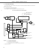
CHAPTER 5. PERIPHERAL HARDWARE FUNCTIONS
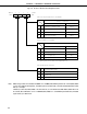
(2) System clock oscillation circuit
The system clock oscillation circuit oscillates by means of a crystal resonator or ceramic resonator connected
to the X1 and X2 pins (standard: 4.194304 MHz).
An external clock can also be input.
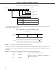
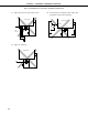
Fig. 5-12 System Clock Oscillation Circuit External Circuitry
(a) Crystal/ceramic oscillation (b) External clock
External
Clock
X1
X2
Note 1. When an external clock is input, STOP mode cannot be set. If STOP mode is set, the X1 pin is shorted
to VSS (GND potential) internally to suppress clock oscillation circuit leakage.
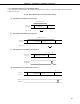
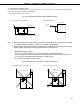
2. When using the system clock generation circuit the area enclosed in dotted line in Fig. 5-12 should be
wired in order to avoid effects of wiring capacitance etc., as shown below.
• Minimize the length of wiring
• Do not cross other signal lines, or position wiring close to a variable high current.
• The connecting point of the oscillator capacitor should always be of the same potential as V
DD. Do
not connect it to the supply pattern where there is a high current.
• Do not pick up the signal from the oscillator.
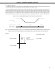
Fig. 5-13 Example of Poor Resonator Connection Circuit (1/2)
(a) Long connection circuit wiring (b) Crossed signal lines
X1 X2
V
DD
V
DD
X1 X2
V
DD
V
DD
µ
PD75402A
µ
PD75402A
µ
PD75402A
PORTn
n = 0,1,2,3,5,6,
µ
PD75402A
Crystal Resonator
or Ceramic Oscillator
X1
X2
V
DD
V
DD
(Standard 4.194304 MHz)