
Electronics America 8-Bit Single-Chip Microcontrollers User's Manual


272
CHAPTER 14 A/D CONVERTER
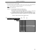
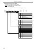
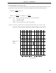
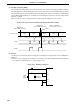
(3) External interrupt mode register 1 (INTM1)
This register sets the valid edge for INTP3 to INTP6.
INTM1 is set with an 8-bit memory manipulation instruction.
RESET input sets INTM1 to 00H.
Figure 14-5. External Interrupt Mode Register 1 Format
ES71
7
ES70
6
ES61 ES60
4
ES51
3210
FFEDH
Address
INTM1
Symbol
ES50 ES41 ES40
5
00H
After
Reset
R/W
R/W
ES41
0
0
1
1
ES40
0
1
0
1
INTP3 Valid Edge Selection
Falling edge
Rising edge
Setting prohibited
Both falling and rising edges
ES51
0
0
1
1
ES50
0
1
0
1
INTP4 Valid Edge Selection
Falling edge
Rising edge
Setting prohibited
Both falling and rising edges
ES61
0
0
1
1
ES60
0
1
0
1
INTP5 Valid Edge Selection
Falling edge
Rising edge
Setting prohibited
Both falling and rising edges
ES71
0
0
1
1
ES70
0
1
0
1
INTP6 Valid Edge Selection
Falling edge
Rising edge
Setting prohibited
Both falling and rising edges