
Electronics America 8-Bit Single-Chip Microcontrollers User's Manual


471
CHAPTER 19 SERIAL INTERFACE CHANNEL 2
When the 3-wire serial I/O mode is used, set BRGC as described below.
(i) When the baud rate generator is not used:
Select a serial clock frequency with TPS0 to TPS3. Be sure then to set MDL0 to MDL3 to 1,1,1,1.
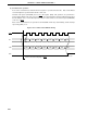
The serial clock frequency becomes 1/2 of the source clock frequency for the 5-bit counter.
(ii) When the baud rate generator is used:
Select a serial clock frequency with TPS0 to TPS3. Be sure then to set MDL0 to MDL3 to 1,1,1,1.
The serial clock frequency is calculated by the following formula:
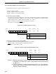
Serial clock frequency= [H
z]
Remarks 1. f
X : Main system clock oscillation frequency
2. fXX : Main system clock frequency (fX or fX/2)
3. n : Value set in TPS0 to TPS3 (1 ≤ n ≤ 11)
4. k : Value set in MDL0 to MDL3 (0 ≤ k ≤ 14)
fXX
2
n
x (k + 16)