
Electronics America 8-Bit Single-Chip Microcontrollers User's Manual


544
CHAPTER 25 ROM CORRECTION
Correction place
Internal ROM
Internal ROM
JUMP
FFFFH
F7FFH
F7FDH
xxxxH
0000H
(1)
(2)
(3)
BR !JUMP
Correction program
25.6 Program Execution Flow
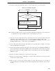
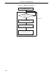
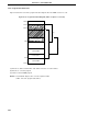
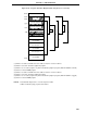
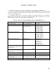
Figures 25-9 and 25-10 show the program transition diagrams when the ROM correction is used.
Figure 25-9. Program Transition Diagram (when one place is corrected)
(1) Branches to address F7FDH when fetch address matches correction address
(2) Branches to correction program
(3) Returns to internal ROM program
Remark Area filled with diagonal lines : Internal expansion RAM
JUMP : Correction program start address