
Electronics America 8-Bit Single-Chip Microcontrollers User's Manual

222
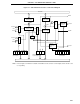
CHAPTER 9 8-BIT TIMER/EVENT COUNTERS 1 AND 2
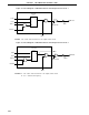
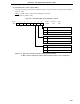
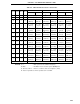
Figure 9-2. Block Diagram of 8-Bit Timer/Event Counter Output Control Circuit 1
Remark The section in the broken line is an output control circuit.
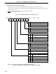
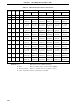
Figure 9-3. Block Diagram of 8-Bit Timer/Event Counter Output Control Circuit 2
Remarks 1. The section in the broken line is an output control circuit.
2. f
SCK : Serial clock frequency
LVR2
LVS2
TOC15
INTTM2
R
S
INV
Level F/F
(LV2)
f
SCK
P32
Output Latch
PM32
TOE2
TO2/P32
Q
LVR1
LVS1
TOC11
INTTM1
R
S
INV
Q
P31
Output Latch
TOE1
PM31
TO1/P31
Level F/F
(LV1)