
Electronics America 8-Bit Single-Chip Microcontrollers User's Manual


495
CHAPTER 21 INTERRUPT AND TEST FUNCTIONS
t
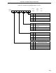
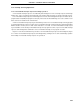
SMP
Sampling Clock
INTP0
PIF0
"L"
Because INTP0 level is not high level at the time of sampling,
PIF0 flag remains at low level.
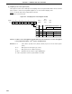
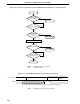
t
SMP
Sampling Clock
INTP0
PIF0
<1> <2>
Because the sampled INTP0 level is high level twice in succession in <2>,
PIF0 flag is set to 1.
(b) When input is equal to or twice the sampling cycle (tSMP)
When the sampled INTP0 input level is active twice in succession, the noise eliminator sets interrupt request
flag (PIF0) to 1.
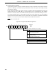
Figure 21-8 shows the noise eliminator input/output timing.
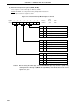
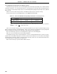
Figure 21-8. Noise Eliminator Input/Output Timing (during rising edge detection)
(a) When input is less than the sampling cycle (t
SMP)
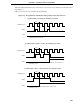
t
SMP
Sampling Clock
INTP0
PIF0
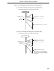
When INTP0 level becomes high level twice in succession,
PIF0 flag is set to 1.
(c) When input is twice or more than the cycle frequency (tSMP)