User’s Manual µPD78078, 78078Y Subseries 8-bit Single-chip Microcontrollers µPD78076 µPD78078 µPD78P078 µPD78076Y µPD78078Y µPD78P078Y Document No.
[MEMO] 2
NOTES FOR CMOS DEVICES 1 PRECAUTION AGAINST ESD FOR SEMICONDUCTORS Note: Strong electric field, when exposed to a MOS device, can cause destruction of the gate oxide and ultimately degrade the device operation. Steps must be taken to stop generation of static electricity as much as possible, and quickly dissipate it once, when it has occurred. Environmental control must be adequate. When it is dry, humidifier should be used. It is recommended to avoid using insulators that easily build static electricity.
The export of these products from Japan is regulated by the Japanese government. The export of some or all of these products may be prohibited without governmental license. To export or re-export some or all of these products from a country other than Japan may also be prohibited without a license from that country. Please call an NEC sales representative.
Regional Information Some information contained in this document may vary from country to country. Before using any NEC product in your application, please contact the NEC office in your country to obtain a list of authorized representatives and distributors.
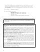
Major Revisions in This Edition Page Throughout Description The following products have been changed from “under development” to “already developed”. µPD78078Y Subseries: µPD78076Y, 78078Y, 78P078Y The following packages have been added to the µPD78078Y Subseries. 100-pin plastic LQFP (Fine pitch) (14 × 14 mm, resin thickness 1.4 mm) p. 139 to 143, 149, 153 Block diagrams of ports have been changed. Figure 6-5. Block Diagram of P20, P21, P23 to P26, Figure 6-6. Block Diagram of P22 and P27, Figure 6-7.
INTRODUCTION Readers This manual has been prepared for user engineers who understand the functions of the µPD78078 and 78078Y Subseries and design and develop its application systems and programs. The µPD78078 and 78078Y Subseries consist of the following members.
Chapter Organization: This manual divides the descriptions for the µPD78078 and 78078Y Subseries into different chapters as shown below. Read only the chapters related to the device you use.
Differences between µPD78078 and µPD78078Y Subseries The µPD78078 and µPD78078Y Subseries are different in the following functions of the serial interface channel 0.
• Development Tool Documents (User’s Manuals) Document Name Document No.
• Documents for Embedded Software (User’s Manuals) Document Name Document No. English 78K/0 Series Real-time OS 78K/0 Series OS MX78K0 Japanese Basics U11537E U11537J Installation U11536E U11536J Basics U12257E U12257J • Other Documents Document Name Document No.
[MEMO] 12
TABLE OF CONTENTS CHAPTER 1 OUTLINE (µPD78078 SUBSERIES) ................................................................................. 1.1 Features .................................................................................................................................. 1.2 Application Fields .................................................................................................................. 1.3 Ordering Information .................................................................
3.2.17 AVSS ............................................................................................................................................. 76 3.2.18 RESET ......................................................................................................................................... 76 3.2.19 X1 and X2 .................................................................................................................................... 76 3.2.20 XT1 and XT2 .............................
5.2 5.3 5.4 Processor Registers ............................................................................................................ 110 5.2.1 Control registers ........................................................................................................................ 110 5.2.2 General registers ....................................................................................................................... 113 5.2.3 Special function register (SFR) ........................
CHAPTER 7 CLOCK GENERATOR .................................................................................................... 7.1 Clock Generator Functions ................................................................................................ 7.2 Clock Generator Configuration .......................................................................................... 7.3 Clock Generator Control Register ..................................................................................... 7.
CHAPTER 10 8-BIT TIMER/EVENT COUNTERS 5 AND 6 ................................................................. 10.1 8-Bit Timer/Event Counters 5 and 6 Functions ............................................................... 10.2 8-Bit Timer/Event Counters 5 and 6 Configurations ...................................................... 10.3 8-Bit Timer/Event Counters 5 and 6 Control Registers ................................................. 10.4 8-Bit Timer/Event Counters 5 and 6 Operations .................
CHAPTER 16 16.1 D/A 16.2 D/A 16.3 D/A 16.4 D/A 16.5 D/A D/A CONVERTER ......................................................................................................... Converter Functions .................................................................................................... Converter Configuration ............................................................................................. Converter Control Registers ....................................................................
CHAPTER 21 REAL-TIME OUTPUT PORT ........................................................................................ 21.1 Real-Time Output Port Functions ..................................................................................... 21.2 Real-Time Output Port Configuration ............................................................................... 21.3 Real-Time Output Port Control Registers ........................................................................
CHAPTER 27 µPD78P078, 78P078Y .................................................................................................. 27.1 Internal Memory Size Switching Register ........................................................................ 27.2 Internal Extension RAM Size Switching Register ........................................................... 27.3 PROM Programming ............................................................................................................ 569 570 571 572 27.
LIST OF FIGURES (1/9) Figure No. Title Page 3-1 List of Pin Input/Output Circuits ................................................................................................... 80 4-1 List of Pin Input/Output Circuits ................................................................................................... 98 5-1 Memory Map (µPD78076, 78076Y) ........................................................................................... 101 5-2 Memory Map (µPD78078, 78078Y) ...........
LIST OF FIGURES (2/9) Figure No. Title Page 7-1 Block Diagram of Clock Generator ............................................................................................ 166 7-2 Subsystem Clock Feedback Resistor ........................................................................................ 167 7-3 Processor Clock Control Register Format ................................................................................. 168 7-4 Oscillation Mode Selection Register Format ...............
LIST OF FIGURES (3/9) Figure No. Title Page 8-26 Control Register Settings in External Event Counter Mode ..................................................... 211 8-27 External Event Counter Configuration Diagram ........................................................................ 212 8-28 External Event Counter Operation Timings (with Rising Edge Specified) ............................... 212 8-29 Control Register Settings in Square-Wave Output Mode .........................................
LIST OF FIGURES (4/9) Figure No. 24 Title Page 10-14 8-Bit Timer Control Register Settings for PWM Output Operation .......................................... 264 10-15 PWM Output Operation Timing (Active High Setting) ............................................................... 265 10-16 PWM Output Operation Timings (CRn0 = 00H, Active High Setting) ...................................... 265 10-17 PWM Output Operation Timings (CRn0 = FFH, Active High Setting) ................................
LIST OF FIGURES (5/9) Figure No. Title Page 17-1 Serial Bus Interface (SBI) System Configuration Example ...................................................... 317 17-2 Serial Interface Channel 0 Block Diagram ................................................................................ 318 17-3 Timer Clock Select Register 3 Format ...................................................................................... 322 17-4 Serial Operating Mode Register 0 Format ............................
LIST OF FIGURES (6/9) Figure No. Title Page 18-10 Serial Bus Configuration Example Using 2-Wire Serial I/O Mode ........................................... 385 18-11 2-Wire Serial I/O Mode Timings ................................................................................................. 388 18-12 RELT and CMDT Operations ..................................................................................................... 389 18-13 Example of Serial Bus Configuration Using I2C Bus .........
LIST OF FIGURES (7/9) Figure No. Title Page 19-21 Operation Timings when Using Busy & Strobe Control Option (BUSY0 = 0) ......................... 452 19-22 Operation Timing of the Bit Slippage Detection Function through the Busy Signal (BUSY0 = 1) ................................................................................................................................ 453 19-23 19-24 Automatic Data Transmit/Receive Interval .....................................................................
LIST OF FIGURES (8/9) Figure No. 28 Title Page 22-13 Interrupt Request Acknowledge Processing Algorithm ............................................................. 517 22-14 Interrupt Request Acknowledge Timing (Minimum Time) ......................................................... 518 22-15 Interrupt Request Acknowledge Timing (Maximum Time) ........................................................ 518 22-16 Multiple Interrupt Example ..........................................................
LIST OF FIGURES (9/9) Figure No. Title Page 27-1 Internal Memory Size Switching Register Format ..................................................................... 570 27-2 Internal Extension RAM Size Switching Register Format ........................................................ 571 27-3 Page Program Mode Flowchart ................................................................................................. 574 27-4 Page Program Mode Timing ..............................................
LIST OF TABLES (1/3) Table No. Title Page 1-1 Mask Options of Mask ROM Versions ......................................................................................... 47 1-2 Differences between µPD78078 Subseries and µPD78054 Subseries ..................................... 47 2-1 Mask Options of Mask ROM Versions ......................................................................................... 63 2-2 Differences between µPD78078Y Subseries and µPD78054Y Subseries ......................
LIST OF TABLES (2/3) Table No. 9-9 Title Page Interval Times when 2-Channel 8-Bit Timer/Event Counters (TM1 and TM2) are Used as 16-Bit Timer/Event Counter .................................................................................. 243 9-10 Square-Wave Output Ranges when 2-Channel 8-Bit Timer/Event Counters (TM1 and TM2) are Used as 16-Bit Timer/Event Counter ....................................................... 245 10-1 8-Bit Timer/Event Counters 5 and 6 Interval Times ....................
LIST OF TABLES (3/3) Table No. Title Page 20-3 Relationship between Main System Clock and Baud Rate ...................................................... 467 20-4 Relationship between ASCK Pin Input Frequency and Baud Rate 20-5 Relationship between Main System Clock and Baud Rate ...................................................... 476 20-6 Relationship between ASCK Pin Input Frequency and Baud Rate (When BRGC is set to 00H) ....................................................................
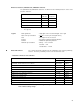
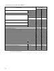
CHAPTER 1 OUTLINE (µPD78078 SUBSERIES) 1.1 Features Internal high-capacity ROM and RAM Type Part Number Program Memory (ROM) µPD78076 48 Kbytes µPD78078 60 Kbytes µPD78P078 60 Kbytes Note 1 Data Memory Internal High-Speed RAM Internal Buffer RAM Internal Expansion RAM 1024 bytes 32 bytes 1024 bytes 1024 bytesNote 2 Notes 1. The capacity of internal PROM can be changed by means of the internal memory size switching register (IMS). 2.
CHAPTER 1 OUTLINE (µPD78078 SUBSERIES) 1.2 Application Fields Cellular phones, cordless telephones, printers, AV equipment, air conditioners, cameras, PPCs, fuzzy home appliances, vending machines, etc. 1.3 Ordering Information Part number Package µPD78076GC-xxx-7EA Internal ROM 100-pin plastic QFP (Fine pitch) (14 x 14 mm, resin thickness 1.45 mm) Mask ROM µPD78076GC-xxx-8EUNote 100-pin plastic LQFP (Fine pitch) (14 x 14 mm, resin thickness 1.
CHAPTER 1 OUTLINE (µPD78078 SUBSERIES) 1.4 Quality Grade Part number Package µPD78076GC-xxx-7EA Quality grades 100-pin plastic QFP (Fine pitch) (14 x 14 mm, resin thickness 1.45 mm) Standard 100-pin plastic LQFP (Fine pitch) (14 x 14 mm, resin thickness 1.4 mm) Standard µPD78076GF-xxx-3BA 100-pin plastic QFP (14 x 20 mm, resin thickness 2.7 mm) Standard µPD78078GC-xxx-7EA 100-pin plastic QFP (Fine pitch) (14 x 14 mm, resin thickness 1.
CHAPTER 1 OUTLINE (µPD78078 SUBSERIES) 1.5 Pin Configuration (Top View) (1) Normal operating mode 100-pin plastic QFP (Fine pitch) (14 x 14 mm, resin thickness 1.45 mm) µPD78076GC-xxx-7EA, 78078GC-xxx-7EA µPD78P078GC-7EA 100-pin plastic LQFP (Fine pitch) (14 x 14 mm, resin thickness 1.
OUTLINE (µPD78078 SUBSERIES) P13/ANI3 P12/ANI2 P11/ANI1 P10/ANI0 AVREF0 AVDD P06/INTP6 P05/INTP5 P04/INTP4 P03/INTP3 P02/INTP2 P01/INTP1/TI01 P00/INTP0/TI00 RESET XT1/P07 XT2 VDD X1 X2 IC (VPP) P127/RTP7 P126/RTP6 P125/RTP5 P124/RTP4 P123/RTP3 CHAPTER 1 100 99 98 97 96 95 94 93 92 91 90 89 88 87 86 85 84 83 82 81 80 79 78 77 76 P14/ANI4 P15/ANI5 P16/ANI6 P17/ANI7 AVSS P130/ANO0 P131/ANO1 AVREF1 P70/SI2/RxD P71/SO2/TxD P72/SCK2/ASCK VSS P20/SI1 P21/SO1 P22/SCK1 P23/STB P24/BUSY P25/SI0/SB0 P26/SO0/SB1 P2
CHAPTER 1 OUTLINE (µPD78078 SUBSERIES) 100-pin plastic QFP (14 x 20 mm) µPD78076GF-xxx-3BA, 78078GF-xxx-3BA µPD78P078GF-3BA 100-pin ceramic WQFN (14 x 20 mm) P96 P95 P94 P93 P92 P91 P90 P37 P36/BUZ P35/PCL P34/TI2 P33/TI1 P32/TO2 P31/TO1 P30/TO0 P103 P102 P101/TI6/TO6 P100/TI5/TO5 P67/ASTB µPD78P078KL-T 100 99 98 97 96 95 94 93 92 91 90 89 88 87 86 85 84 83 82 81 1 80 2 79 3 78 4 77 5 76 6 75 7 74 8 73 9 72 10 71 11 70 12 69 13 68 14 67 15 66 16 65 17 64 18 63 19 62 20 61 21 60 22 59 23 58 24 57 25 56
CHAPTER 1 OUTLINE (µPD78078 SUBSERIES) Pin Identifications A0 to A15 : Address Bus P120 to P127 : Port 12 AD0 to AD7 : Address/Data Bus P130, P131 : Port 13 ANI0 to ANI7 : Analog Input PCL : Programmable Clock ANO0, ANO1 : Analog Output RD : Read Strobe ASCK : Asynchronous Serial Clock RESET : Reset ASTB : Address Strobe RTP0 to RTP7 : Real-time Output Port AVDD : Analog Power Supply RxD : Receive Data AVREF0, AVREF1 : Analog Reference Voltage SB0, SB1 : Seri
CHAPTER 1 OUTLINE (µPD78078 SUBSERIES) (2) PROM programming mode 100-pin plastic QFP (Fine pitch) (14 x 14 mm, resin thickness 1.45 mm) µPD78P078GC-7EA 100-pin plastic LQFP (Fine pitch) (14 x 14 mm, resin thickness 1.4 mm) VDD (L) VSS (L) (L) Note (L) PGM (L) A9 RESET (L) Open VDD (L) Open VPP (L) Under development Cautions 1. (L) 2. VSS : Connect independently to VSS via a pull-down resistor. : Connect to the ground. 3. RESET : Set to the low level. 4.
CHAPTER 1 OUTLINE (µPD78078 SUBSERIES) 100-pin plastic QFP (14 x 20 mm) µPD78P078GF-3BA Cautions 1. (L) 2.
CHAPTER 1 OUTLINE (µPD78078 SUBSERIES) 1.6 78K/0 Series Expansion The products in the 78K/0 Series are listed below. The names in boxes are subseries names. Mass-produced products Products under development The subseries whose name ends with Y support the I2C bus specifications.
CHAPTER 1 OUTLINE (µPD78078 SUBSERIES) The following shows the major differences between subseries products. Function Subseries Name Control ROM Capacity Timer 8-bit 10-bit 8-bit 8-bit 16-bit Watch WDT A/D µPD78075B 32 K to 40 K 4 ch 1 ch 1 ch 1 ch 8 ch µPD78078 48 K to 60 K µPD78070A A/D – D/A 1.8 V – 61 2.7 V 3 ch (Time division 68 UART: 1 ch) 1.8 V µPD78058F 48 K to 60 K 3 ch (UART: 1 ch) 69 2.
CHAPTER 1 OUTLINE (µPD78078 SUBSERIES) 1.
CHAPTER 1 OUTLINE (µPD78078 SUBSERIES) 1.8 Outline of Function µPD78076 Part Number µPD78078 µPD78P078 Item Internal ROM memory Mask ROM PROM 48 Kbytes High-speed RAM 1024 bytes Buffer RAM 32 bytes Expansion RAM 1024 bytes 60 Kbytes 60 KbytesNote 1 1024 bytesNote 2 Memory space 64 Kbytes General register 8 bits x 8 x 4 banks Minimum instruction execution time With main system clock selected 0.4 µs/0.8 µs/1.6 µs/3.2 µs/6.4 µs/12.8 µs (@ 5.
CHAPTER 1 Part Number OUTLINE (µPD78078 SUBSERIES) µPD78076 µPD78078 µPD78P078 Item Vectored Maskable interrupt Internal: 15 External: 7 source Non-maskable Internal: 1 Software Internal: 1 Test input Internal: 1 External: 1 Power supply voltage VDD = 1.8 to 5.5 V Operating ambient temperature T A = –40 to +85°C Package • 100-pin plastic QFP (Fine pitch) (14 x 14 mm, resin thickness 1.45 mm) • 100-pin plastic LQFPNote (Fine pitch) (14 x 14 mm, resin thickness 1.
CHAPTER 1 OUTLINE (µPD78078 SUBSERIES) 1.9 Mask Options The mask ROM versions (µPD78076, 78078) provide pull-up register mask options which allow users to specify whether to connect a pull-up register to a specific port pin when the user places an order for the device production. Using this mask option when pull-up resistors are required reduces the number of components to add to the device, resulting in board space saving. The mask options provided in the µPD78078 Subseries are shown in Table 1-1.
[MEMO] 48
CHAPTER 2 OUTLINE (µPD78078Y SUBSERIES) 2.1 Features Internal high-capacity ROM and RAM Type Data Memory Program Memory (ROM) Internal High-Speed RAM Internal Buffer RAM Internal Expansion RAM µPD78076Y 48 Kbytes 1024 bytes µPD78078Y 60 Kbytes µPD78P078Y 60 KbytesNote 1 Part Number Notes 32 bytes 1024 bytes 1024 bytesNote 2 1. The capacity of internal PROM can be changed using the internal memory size switching register (IMS). 2.
CHAPTER 2 OUTLINE (µPD78078Y SUBSERIES) 2.2 Application Fields Cellular phones, cordless telephones, printers, AV equipment, air conditioners, cameras, PPCs, fuzzy home appliances, vending machines, etc. 2.3 Ordering Information Part number Package µPD78076YGC-xxx-8EU Note 100-pin plastic LQFP (Fine pitch) (14 x 14 mm, resin thickness 1.4 mm) Mask ROM 100-pin plastic QFP (14 x 20 mm, resin thickness 2.7 mm) Mask ROM 100-pin plastic LQFP (Fine pitch) (14 x 14 mm, resin thickness 1.
CHAPTER 2 OUTLINE (µPD78078Y SUBSERIES) 2.4 Quality Grade Part number Package Quality grades µPD78076YGC-xxx-8EUNote 100-pin plastic LQFP (Fine pitch) (14 x 14 mm, resin thickness 1.4 mm) Standard µPD78076YGF-xxx-3BA Standard 100-pin plastic QFP (14 x 20 mm, resin thickness 2.7 mm) µPD78078YGC-xxx-8EUNote 100-pin plastic LQFP (Fine pitch) (14 x 14 mm, resin thickness 1.4 mm) Standard µPD78078YGF-xxx-3BA 100-pin plastic QFP (14 x 20 mm, resin thickness 2.
CHAPTER 2 OUTLINE (µPD78078Y SUBSERIES) 2.5 Pin Configuration (Top View) (1) Normal operating mode 100-pin plastic LQFP (Fine pitch) (14 x 14 mm, resin thickness 1.
OUTLINE (µPD78078Y SUBSERIES) P13/ANI3 P12/ANI2 P11/ANI1 P10/ANI0 AVREF0 AVDD P06/INTP6 P05/INTP5 P04/INTP4 P03/INTP3 P02/INTP2 P01/INTP1/TI01 P00/INTP0/TI00 RESET XT1/P07 XT2 VDD X1 X2 IC (VPP) P127/RTP7 P126/RTP6 P125/RTP5 P124/RTP4 P123/RTP3 CHAPTER 2 100 99 98 97 96 95 94 93 92 91 90 89 88 87 86 85 84 83 82 81 80 79 78 77 76 P14/ANI4 P15/ANI5 P16/ANI6 P17/ANI7 AVSS P130/ANO0 P131/ANO1 AVREF1 P70/SI2/RxD P71/SO2/TxD P72/SCK2/ASCK VSS P20/SI1 P21/SO1 P22/SCK1 P23/STB P24/BUSY P25/SI0/SB0/SDA0 P26/SO0/
CHAPTER 2 OUTLINE (µPD78078Y SUBSERIES) 100-pin plastic QFP (14 x 20 mm) µPD78076YGF-xxx-3BA µPD78078YGF-xxx-3BA, 78P078YGF-3BA µPD78P078YKL-T 100 99 98 97 96 95 94 93 92 91 90 89 88 87 86 85 84 83 82 81 1 80 2 79 3 78 4 77 5 76 6 75 7 74 8 73 9 72 10 71 11 70 12 69 13 68 14 67 15 66 16 65 17 64 18 63 19 62 20 61 21 60 22 59 23 58 24 57 25 56 26 55 27 54 28 53 29 52 51 30 31 32 33 34 35 36 37 38 39 40 41 42 43 44 45 46 47 48 49 50 P16/ANI6 P17/ANI7 AVSS P130/ANO0 P131/ANO1 AVREF1 P70/SI2/RxD P71/SO2/T
CHAPTER 2 OUTLINE (µPD78078Y SUBSERIES) Pin Identifications A0 to A15 : Address Bus P130, P131 : Port 13 AD0 to AD7 : Address/Data Bus PCL : Programmable Clock ANI0 to ANI7 : Analog Input RD : Read Strobe ANO0, ANO1 : Analog Output RESET : Reset ASCK : Asynchronous Serial Clock RTP0 to RTP7 : Real-time Output Port ASTB : Address Strobe RxD : Receive Data AVDD : Analog Power Supply SB0, SB1 : Serial Bus AVREF0, AVREF1 : Analog Reference Voltage SCK0 to SCK2 : Serial Clock AV
CHAPTER 2 OUTLINE (µPD78078Y SUBSERIES) (2) PROM programming mode 100-pin plastic QFP (Fine pitch) (14 x 14 mm, resin thickness 1.45 mm) µPD78P078YGC-7EA 100-pin plastic LQFP (Fine pitch) (14 x 14 mm, resin thickness 1.4 mm) VDD (L) VSS (L) (L) Note (L) PGM (L) A9 RESET (L) Open VDD (L) Open VPP (L) Under development Cautions 1. (L) 2. VSS : Connect independently to VSS via a pull-down resistor. : Connect to the ground. 3. RESET : Set to the low level. 4.
CHAPTER 2 OUTLINE (µPD78078Y SUBSERIES) 100-pin plastic QFP (14 x 20 mm) µPD78P078YGF-3BA 100-pin ceramic WQFN 2.
CHAPTER 2 OUTLINE (µPD78078Y SUBSERIES) 2.6 78K/0 Series Expansion The products in the 78K/0 Series are listed below. The names in boxes are subseries names. Mass-produced products Products under development The subseries whose name ends with Y support the I2C bus specifications. Control 100-pin µPD78075B 100-pin µPD78078 µPD78078Y 100-pin µPD78070A µPD78070AY ROM-less version of µPD78078 Enhanced serial I/O of µPD78078Y and functions are defined.
CHAPTER 2 OUTLINE (µPD78078Y SUBSERIES) Major differences among Y subseries are tabulated below. Function Subseries Control µPD78078Y ROM Capacity I/O VDD MIN. 88 1.
CHAPTER 2 OUTLINE (µPD78078Y SUBSERIES) 2.
CHAPTER 2 OUTLINE (µPD78078Y SUBSERIES) 2.8 Outline of Function µPD78076Y Part Number µPD78078Y µPD78P078Y Item Mask ROM PROM ROM 48 Kbytes Internal memory High-speed RAM 1024 bytes Buffer RAM 32 bytes Expansion RAM 1024 bytes 60 Kbytes 60 KbytesNote 1 1024 bytes Memory space 64 Kbytes General register 8 bits x 8 x 4 banks Minimum instruction execution time With main system clock selected 0.4 µs/0.8 µs/1.6 µs/3.2 µs/6.4 µs/12.8 µs (@ 5.
CHAPTER 2 Part Number OUTLINE (µPD78078Y SUBSERIES) µPD78076Y µPD78078Y µPD78P078Y Item Vectored Maskable interrupt Internal: 15 External: 7 source Non-maskable Internal: 1 Software Internal: 1 Test input Internal: 1 External: 1 Power supply voltage VDD = 1.8 to 5.5 V Operating ambient temperature T A = –40 to +85°C Package • 100-pin plastic LQFPNote (Fine pitch) (14 x 14 mm, resin thickness 1.4 mm) • 100-pin plastic QFP (14 x 20 mm, resin thickness 2.
CHAPTER 2 OUTLINE (µPD78078Y SUBSERIES) 2.9 Mask Options The mask ROM versions (µPD78076Y, 78078Y) provide pull-up register mask options which allow users to specify whether to connect a pull-up register to a specific port pin when the user places an order for the device production. Using this mask option when pull-up resistors are required reduces the number of components to add to the device, resulting in board space saving. The mask options provided in the µPD78078Y Subseries are shown in Table 2-1.
[MEMO] 64
CHAPTER 3 PIN FUNCTION (µPD78078 SUBSERIES) 3.1 Pin Function List 3.1.1 Normal operating mode pins (1) Port pins (1/3) Pin Name Input/Output P00 Function Input Input only P01 Input/output mode can be specified P02 bit-wise. After Reset Alternate Function Input INTP0/TI00 INTP1/TI01 INTP2 P03 Input/ Port 0. If used as an input port, an on-chip P04 output 8-bit input/output port. pull-up resistor can be connected INTP4 by software.
CHAPTER 3 PIN FUNCTION (µPD78078 SUBSERIES) (1) Port pins (2/3) Pin Name Input/Output Function After Reset Alternate Function P30 TO0 P31 TO1 P32 P33 Port 3. Input/ TO2 8-bit input/output port. TI1 Input P34 output Input/output mode can be specified bit-wise. TI2 P35 If used as an input port, an on-chip pull-up resistor can be connected by PCL P36 software. BUZ P37 — Port 4. 8-bit input/output port. P40 to P47 Input/ Input/output mode can be specified in 8-bit units.
CHAPTER 3 PIN FUNCTION (µPD78078 SUBSERIES) (1) Port pins (3/3) Pin Name Input/Output Function P90 P91 Input/output mode can be N-ch open-drain input/output port. On-chip pull-up resistor can be specified by mask option. (Mask ROM version only). LEDs can be driven directly. specified bit-wise. If used as an input port, an on-chip Port 9. P92 7-bit input/output port. Input/ P93 output P94 P95 pull-up resistor can be connected P96 by software. After Reset Alternate Function Input — Port 10.
CHAPTER 3 PIN FUNCTION (µPD78078 SUBSERIES) (2) Non-port pins (1/2) Pin Name Input/Output Function After Reset Alternate Function INTP0 P00/TI00 INTP1 P01/TI01 INTP2 INTP3 External interrupt request inputs with specifiable valid edges (rising edge, Input falling edge, both rising and falling edges).
CHAPTER 3 PIN FUNCTION (µPD78078 SUBSERIES) (2) Non-port pins (2/2) Pin Name Input/Output Function AD0 to AD7 Input/Output Low-order address/data bus when expanding external memory After Reset Alternate Function Input P40 to P47 A0 to A7 Output Low-order address bus when expanding external memory Input P80 to P87 A8 to A15 Output High-order address bus when expanding external memory Input P50 to P57 RD Output Strobe signal output for read operation from external memory Input P64 WR St
CHAPTER 3 PIN FUNCTION (µPD78078 SUBSERIES) 3.2 Description of Pin Functions 3.2.1 P00 to P07 (Port 0) These are 8-bit input/output ports. Besides serving as input/output ports, they function as an external interrupt request input, an external count clock input to the timer, a capture trigger signal input, and crystal connection for subsystem oscillation. The following operating modes can be specified bit-wise.
CHAPTER 3 PIN FUNCTION (µPD78078 SUBSERIES) 3.2.3 P20 to P27 (Port 2) These are 8-bit input/output ports. Besides serving as input/output ports, they function as data input/output to/ from the serial interface, clock input/output, automatic transmit/receive busy input, and strobe output functions. The following operating modes can be specified bit-wise. (1) Port mode These ports function as 8-bit input/output ports. They can be specified bit-wise as input or output ports with port mode register 2 (PM2).
CHAPTER 3 PIN FUNCTION (µPD78078 SUBSERIES) 3.2.4 P30 to P37 (Port 3) These are 8-bit input/output ports. Beside serving as input/output ports, they function as timer input/output, clock output and buzzer output. The following operating modes can be specified bit-wise. (1) Port mode These ports function as 8-bit input/output ports. They can be specified bit-wise as input or output ports with port mode register 3 (PM3).
CHAPTER 3 PIN FUNCTION (µPD78078 SUBSERIES) 3.2.6 P50 to P57 (Port 5) These are 8-bit input/output ports. Besides serving as input/output ports, they function as an address bus. Port 5 can drive LEDs directly. The following operating modes can be specified bit-wise. (1) Port mode These ports function as 8-bit input/output ports. They can be specified bit-wise as input/output ports with port mode register 5 (PM5).
CHAPTER 3 PIN FUNCTION (µPD78078 SUBSERIES) 3.2.8 P70 to P72 (Port 7) This is a 3-bit input/output port. In addition to its use as an input/output port, it also has serial interface data input/ output and clock input/output functions. The following operating modes can be specified bit-wise. (1) Port mode Port 7 functions as a 3-bit input/output port. Bit-wise specification as an input port or output port is possible by means of port mode register 7 (PM7).
CHAPTER 3 PIN FUNCTION (µPD78078 SUBSERIES) 3.2.10 P90 to P96 (Port 9) These are 7-bit input/output ports. P90 to P93 can drive LEDs directly. They can be specified bit-wise as input or output ports with port mode register 9 (PM9). P90 to P93 are N-ch open-drain pins. Mask ROM version product can contain pull-up resistors with the mask option. When P94 to P96 are used as input ports, on-chip pull-up resistors can be connected by defining the pull-up resistor option register H (PUOH). 3.2.
CHAPTER 3 PIN FUNCTION (µPD78078 SUBSERIES) 3.2.13 P130 and P131 (Port 13) These are 2-bit input/output ports. Besides serving as input/output ports, they are used for D/A converter analog output. The following operating modes can be specified bit-wise. (1) Port mode These ports function as 2-bit input/output ports. They can be specified bit-wise as input or output ports with port mode register 13 (PM13).
CHAPTER 3 PIN FUNCTION (µPD78078 SUBSERIES) 3.2.21 VDD Positive power supply pin 3.2.22 VSS Ground potential pin 3.2.23 VPP (µPD78P078 only) High-voltage apply pin for PROM programming mode setting and program write/verify. Connect directly to VSS in normal operating mode. 3.2.24 IC (Mask ROM version only) The IC (Internally Connected) pin is provided to set the test mode to check the µPD78078 at delivery. Connect it directly to the VSS with the shortest possible wire in the normal operating mode.
CHAPTER 3 PIN FUNCTION (µPD78078 SUBSERIES) 3.3 Input/output Circuits and Recommended Connection of Unused Pins Table 2-1 shows the input/output circuit types of pins and the recommended conditions for unused pins. Refer to Figure 3-1 for the configuration of the input/output circuit of each type. Table 3-1.
CHAPTER 3 PIN FUNCTION (µPD78078 SUBSERIES) Table 3-1. Pin Input/Output Circuit Types (2/2) Pin Name Input/Output Circuit Type Input/Output Recommended Connection of Unused Pins P50/A8 to P57/A15 5-A Input/output Connect independently via a resistor to VDD or VSS. P60 to P63 (Mask ROM version) 13-B Input/output Connect independently via a resistor P60 to P63 (µPD78P078) 13-D P64/RD 5-A to VDD. Input/output P65/WR Connect independently via a resistor to VDD or V SS.
PIN FUNCTION (µPD78078 SUBSERIES) CHAPTER 3 Figure 3-1.
CHAPTER 3 PIN FUNCTION (µPD78078 SUBSERIES) Figure 3-1.
[MEMO] 82
CHAPTER 4 PIN FUNCTION (µPD78078Y SUBSERIES) 4.1 Pin Function List 4.1.1 Normal operating mode pins (1) Port pins (1/3) Pin Name Input/Output P00 Function Input Input only P01 Input/output mode can be specified P02 bit-wise. After Reset Alternate Function Input INTP0/TI00 INTP1/TI01 INTP2 P03 Input/ Port 0. If used as an input port, an on-chip P04 output 8-bit input/output port. pull-up resistor can be connected INTP4 by software.
CHAPTER 4 PIN FUNCTION (µPD78078Y SUBSERIES) (1) Port pins (2/3) Pin Name Input/Output Function After Reset Alternate Function P30 TO0 P31 TO1 P32 P33 Port 3. Input/ TO2 8-bit input/output port. TI1 Input P34 output Input/output mode can be specified bit-wise. TI2 P35 If used as an input port, an on-chip pull-up resistor can be connected by PCL P36 software. BUZ P37 — Port 4. 8-bit input/output port. P40 to P47 Input/ Input/output mode can be specified in 8-bit units.
CHAPTER 4 PIN FUNCTION (µPD78078Y SUBSERIES) (1) Port pins (3/3) Pin Name Input/Output Function P90 P91 Input/output mode can be N-ch open-drain input/output port. On-chip pull-up resistor can be specified by mask option. (Mask ROM version only). LEDs can be driven directly. specified bit-wise. If used as an input port, an on-chip Port 9. P92 7-bit input/output port. Input/ P93 output P94 P95 pull-up resistor can be connected P96 by software. After Reset Alternate Function Input Port 10.
CHAPTER 4 PIN FUNCTION (µPD78078Y SUBSERIES) (2) Non-port pins (1/2) Pin Name Input/Output Function After Reset Alternate Function INTP0 P00/TI00 INTP1 P01/TI01 INTP2 INTP3 External interrupt request inputs with specifiable valid edges (rising edge, Input falling edge, both rising and falling edges).
CHAPTER 4 PIN FUNCTION (µPD78078Y SUBSERIES) (2) Non-port pins (2/2) Pin Name Input/Output Function AD0 to AD7 Input/Output Low-order address/data bus when expanding external memory After Reset Alternate Function Input P40 to P47 A0 to A7 Output Low-order address bus when expanding external memory Input P80 to P87 A8 to A15 Output High-order address bus when expanding external memory Input P50 to P57 RD Output Strobe signal output for read operation from external memory Input P64 WR S
CHAPTER 4 PIN FUNCTION (µPD78078Y SUBSERIES) 4.2 Description of Pin Functions 4.2.1 P00 to P07 (Port 0) These are 8-bit input/output ports. Besides serving as input/output ports, they function as an external interrupt request input, an external count clock input to the timer, a capture trigger signal input, and crystal connection for subsystem oscillation. The following operating modes can be specified bit-wise.
CHAPTER 4 PIN FUNCTION (µPD78078Y SUBSERIES) 4.2.3 P20 to P27 (Port 2) These are 8-bit input/output ports. Besides serving as input/output ports, they function as data input/output to/ from the serial interface, clock input/output, automatic transmit/receive busy input, and strobe output functions. The following operating modes can be specified bit-wise. (1) Port mode These ports function as 8-bit input/output ports. They can be specified bit-wise as input or output ports with port mode register 2 (PM2).
CHAPTER 4 PIN FUNCTION (µPD78078Y SUBSERIES) 4.2.4 P30 to P37 (Port 3) These are 8-bit input/output ports. Beside serving as input/output ports, they function as timer input/output, clock output and buzzer output. The following operating modes can be specified bit-wise. (1) Port mode These ports function as 8-bit input/output ports. They can be specified bit-wise as input or output ports with port mode register 3 (PM3).
CHAPTER 4 PIN FUNCTION (µPD78078Y SUBSERIES) 4.2.6 P50 to P57 (Port 5) These are 8-bit input/output ports. Besides serving as input/output ports, they function as an address bus. Port 5 can drive LEDs directly. The following operating modes can be specified bit-wise. (1) Port mode These ports function as 8-bit input/output ports. They can be specified bit-wise as input/output ports with port mode register 5 (PM5).
CHAPTER 4 PIN FUNCTION (µPD78078Y SUBSERIES) 4.2.8 P70 to P72 (Port 7) This is a 3-bit input/output port. In addition to its use as an input/output port, it also has serial interface data input/ output and clock input/output functions. The following operating modes can be specified bit-wise. (1) Port mode Port 7 functions as a 3-bit input/output port. Bit-wise specification as an input port or output port is possible by means of port mode register 7 (PM7).
CHAPTER 4 PIN FUNCTION (µPD78078Y SUBSERIES) 4.2.10 P90 to P96 (Port 9) These are 7-bit input/output ports. P90 to P93 can drive LEDs directly. They can be specified bit-wise as input or output ports with port mode register 9 (PM9). P90 to P93 are N-ch open-drain pins. Mask ROM version product can contain pull-up resistors with the mask option. When P94 to P96 are used as input ports, on-chip pull-up resistors can be connected by defining the pull-up resistor option register H (PUOH). 4.2.
CHAPTER 4 PIN FUNCTION (µPD78078Y SUBSERIES) 4.2.13 P130 and P131 (Port 13) These are 2-bit input/output ports. Besides serving as input/output ports, they are used for D/A converter analog output. The following operating modes can be specified bit-wise. (1) Port mode These ports function as 2-bit input/output ports. They can be specified bit-wise as input or output ports with port mode register 13 (PM13).
CHAPTER 4 PIN FUNCTION (µPD78078Y SUBSERIES) 4.2.21 VDD Positive power supply pin 4.2.22 VSS Ground potential pin 4.2.23 VPP (µPD78P078Y only) High-voltage apply pin for PROM programming mode setting and program write/verify. Connect directly to VSS in normal operating mode. 4.2.24 IC (Mask ROM version only) The IC (Internally Connected) pin is provided to set the test mode to check the µPD78078Y at delivery. Connect it directly to the VSS with the shortest possible wire in the normal operating mode.
CHAPTER 4 PIN FUNCTION (µPD78078Y SUBSERIES) 4.3 Input/output Circuits and Recommended Connection of Unused Pins Table 4-1 shows the input/output circuit types of pins and the recommended conditions for unused pins. Refer to Figure 4-1 for the configuration of the input/output circuit of each type. Table 4-1.
CHAPTER 4 PIN FUNCTION (µPD78078Y SUBSERIES) Table 4-1. Pin Input/Output Circuit Types (2/2) Pin Name Input/Output Circuit Type Input/Output Recommended Connection of Unused Pins P50/A8 to P57/A15 5-A Input/output Connect independently via a resistor to VDD or VSS. P60 to P63 (Mask ROM version) 13-B Input/output Connect independently via a resistor P60 to P63 (µPD78P078Y) 13-D P64/RD 5-A to VDD. Input/output P65/WR Connect independently via a resistor to VDD or V SS.
PIN FUNCTION (µPD78078Y SUBSERIES) CHAPTER 4 Figure 4-1.
PIN FUNCTION (µPD78078Y SUBSERIES) CHAPTER 4 Figure 4-1.
[MEMO] 100
CHAPTER 5 CPU ARCHITECTURE 5.1 Memory Spaces The µPD78078 and 78078Y Subseries allow access to a memory space of 64 Kbytes. Figures 5-1 to 5-3 shows memory maps. Figure 5-1.
CHAPTER 5 CPU ARCHITECTURE Figure 5-2.
CHAPTER 5 CPU ARCHITECTURE Figure 5-3.
CHAPTER 5 CPU ARCHITECTURE 5.1.1 Internal program memory space The internal program memory space stores programs and table data. This is generally accessed by the program counter (PC). The µPD78078 and 78078Y Subseries have various size of internal ROMs or PROM as shown below. Table 5-1.
CHAPTER 5 CPU ARCHITECTURE (1) Vector table area The 64-byte area 0000H to 003FH is reserved as a vector table area. The RESET input and program start addresses for branch upon generation of each interrupt request are stored in the vector table area. Of the 16-bit address, low-order 8 bits are stored at even addresses and high-order 8 bits are stored at odd addresses. Table 5-2.
CHAPTER 5 CPU ARCHITECTURE 5.1.2 Internal data memory space The µPD78078 and 78078Y Subseries units incorporate the following RAMs. (1) Internal high-speed RAM This is a 1024 x 8-bit configuration in the area FB00H to FEFFH 4 banks of general registers, each bank consisting of eight 8-bit registers, are allocated in the 32-byte area FEE0H to FEFFH. The internal high-speed RAM can also be used as a stack memory.
CHAPTER 5 CPU ARCHITECTURE 5.1.5 Data memory addressing Addressing is a method to specify the instruction address to be executed next and the register and memory address to be manipulated when instructions are executed. The instruction address to be executed next is addressed by the program counter (PC) (for details, refer to 5.3 Instruction Address Addressing).
CHAPTER 5 CPU ARCHITECTURE Figure 5-5.
CHAPTER 5 CPU ARCHITECTURE Figure 5-6.
CHAPTER 5 CPU ARCHITECTURE 5.2 Processor Registers The µPD78078 and 78078Y Subseries units incorporate the following processor registers. 5.2.1 Control registers The control registers control the program sequence, statuses, and stack memory. The control registers consist of a program counter (PC), a program status word (PSW), and a stack pointer (SP). (1) Program counter (PC) The program counter is a 16-bit register which holds the address information of the next program to be executed.
CHAPTER 5 CPU ARCHITECTURE (a) Interrupt enable flag (IE) This flag controls the interrupt request acknowledge operations of the CPU. When IE = 0, the IE is set to interrupt disabled (DI) status. All interrupts except non-maskable interrupt are disabled. When IE = 1, the IE is set to interrupt enabled (EI) status and interrupt request acknowledge is controlled with an in-service priority flag (ISP), an interrupt mask flag for various interrupt sources, and a priority specification flag.
CHAPTER 5 CPU ARCHITECTURE (3) Stack pointer (SP) This is a 16-bit register to hold the start address of the memory stack area. Only the internal high-speed RAM area can be set as the stack area. Figure 5-9. Stack Pointer Configuration 15 SP 0 SP15 SP14 SP13 SP12 SP11 SP10 SP9 SP8 SP7 SP6 SP5 SP4 SP3 SP2 SP1 SP0 The SP is decremented ahead of write (save) to the stack memory and is incremented after read (reset) from the stack memory.
CHAPTER 5 CPU ARCHITECTURE 5.2.2 General registers A general register is mapped at particular addresses (FEE0H to FEFFH) of the data memory. It consists of 4 banks, each bank consisting of eight 8-bit registers (X, A, C, B, E, D, L, and H). Each register can also be used as an 8-bit register. Two 8-bit registers can be used in pairs as a 16-bit register (AX, BC, DE, and HL).
CHAPTER 5 CPU ARCHITECTURE 5.2.3 Special function register (SFR) Unlike a general register, each special function register has special functions. It is allocated in the FF00H to FFFFH area. The special function registers can be manipulated in a similar way as the general registers, by using operation, transfer, or bit-manipulate instructions. The special function regsters are read from and written to in specified manipulation bit units (1, 8, and/or 16) depending on the register type.
CHAPTER 5 CPU ARCHITECTURE Table 5-3.
CHAPTER 5 CPU ARCHITECTURE Table 5-3.
CHAPTER 5 CPU ARCHITECTURE Table 5-3.
CHAPTER 5 CPU ARCHITECTURE 5.3 Instruction Address Addressing An instruction address is determined by program counter (PC) contents. The PC contents are normally incremented (+1 for each byte) automatically according to the number of bytes of an instruction to be fetched each time another instruction is executed. However, when a branch instruction is executed, the branch destination information is set to the PC and branched by the following addressing.
CHAPTER 5 CPU ARCHITECTURE 5.3.2 Immediate addressing [Function] Immediate data in the instruction word is transferred to the program counter (PC) and branched. This function is carried out when the CALL !addr16 or BR !addr16 or CALLF !addr11 instruction is executed. CALL !addr16 and BR !addr16 instructions can branch to all the memory space. CALLF !addr11 instruction branches to the area from 0800H to 0FFFH. [Illustration] In the case of CALL !addr16 and BR !addr16 instructions 7 0 CALL or BR Low Addr.
CHAPTER 5 CPU ARCHITECTURE 5.3.3 Table indirect addressing [Function] Table contents (branch destination address) of the particular location to be addressed by bits 1 to 5 of the immediate data of an operation code are transferred to the program counter (PC) and branched. Table indirect addressing is carried out when the CALLT [addr5] instruction is executed. This instruction can refer to the address stored in the memory table 40H to 7FH and branch to all the memory space.
CHAPTER 5 CPU ARCHITECTURE 5.3.4 Register addressing [Function] Register pair (AX) contents to be specified with an instruction word are transferred to the program counter (PC) and branched. This function is carried out when the BR AX instruction is executed.
CHAPTER 5 CPU ARCHITECTURE 5.4 Operand Address Addressing The following methods are available to specify the register and memory (addressing) which undergo manipulation during instruction execution. 5.4.1 Implied addressing [Function] The register which functions as an accumulator (A and AX) in the general register is automatically (implicitly) addressed. Of the µPD78078 and 78078Y Subseries instruction words, the following instructions employ implied addressing.
CHAPTER 5 CPU ARCHITECTURE 5.4.2 Register addressing [Function] The general register is accessed as an operand. The general register to be accessed is specified with register bank select flags (RBS0 and RBS1) and register specify code (Rn, RPn) in the instruction code. Register addressing is carried out when an instruction with the following operand format is executed. When an 8-bit register is specified, one of the eight registers is specified with 3 bits in the operation code.
CHAPTER 5 CPU ARCHITECTURE 5.4.3 Direct addressing [Function] The memory indicated by immediate data in an instruction word is directly addressed.
CHAPTER 5 CPU ARCHITECTURE 5.4.4 Short direct addressing [Function] The memory to be manipulated in the fixed space is directly addressed with 8-bit data in an instruction word. The fixed space to which this addressing is applied to is the 256-byte space, from FE20H to FF1FH. An internal high-speed RAM and a special function register (SFR) are mapped at FE20H to FEFFH and FF00H to FF1FH, respectively. The SFR area where short direct addressing is applied (FF00H to FF1FH) is a part of the SFR area.
CHAPTER 5 CPU ARCHITECTURE 5.4.5 Special function register (SFR) addressing [Function] The memory-mapped special function register (SFR) is addressed with 8-bit immediate data in an instruction word. This addressing is applied to the 240-byte spaces FF00H to FFCFH and FFE0H to FFFFH. However, the SFR mapped at FF00H to FF1FH can be accessed with short direct addressing.
CHAPTER 5 CPU ARCHITECTURE 5.4.6 Register indirect addressing [Function] The memory is addressed with the contents of the register pair specified as an operand. The register pair to be accessed is specified with the register bank select flag (RBS0 and RBS1) and the register pair specify code in the instruction code. This addressing can be carried out for all the memory spaces.
CHAPTER 5 CPU ARCHITECTURE 5.4.7 Based addressing [Function] 8-bit immediate data is added to the contents of the base register, that is, the HL register pair, and the sum is used to address the memory. The HL register pair to be accessed is in the register bank specified with the register bank select flags (RBS0 and RBS1). Addition is performed by expanding the offset data as a positive number to 16 bits. A carry from the 16th bit is ignored. This addressing can be carried out for all the memory spaces.
CHAPTER 5 CPU ARCHITECTURE 5.4.8 Based indexed addressing [Function] The B or C register contents specified in an instruction are added to the contents of the base register, that is, the HL register pair, and the sum is used to address the memory. The HL, B, and C registers to be accessed are registers in the register bank specified with the register bank select flag (RBS0 and RBS1). Addition is performed by expanding the contents of the B or C register as a positive number to 16 bits.
[MEMO] 130
CHAPTER 6 PORT FUNCTIONS 6.1 Port Functions The µPD78078 and 78078Y Subseries units incorporate two input ports and eighty-six input/output ports. Figure 6-1 shows the port configuration. Every port is capable of 1-bit and 8-bit manipulations and can carry out considerably varied control operations. Besides port functions, the ports can also serve as on-chip hardware input/output pins. Figure 6-1.
CHAPTER 6 PORT FUNCTIONS Table 6-1. Port Functions (µPD78078 Subseries) (1/2) Pin Name Function P00 Input only P01 Alternate Function INTP0/TI00 INTP1/TI01 P02 Input/output mode can be specified bit- INTP2 P03 Port 0. wise. INTP3 P04 8-bit input/output port. If used as an input port, an on-chip pull- INTP4 up resistor can be connected by software. INTP5 P05 P06 INTP6 P07 Input only XT1 Port 1. 8-bit input/output port. P10 to P17 Input/output mode can be specified bit-wise.
CHAPTER 6 PORT FUNCTIONS Table 6-1. Port Functions (µPD78078 Subseries) (2/2) Pin Name Function P60 N-ch open drain input/output port. P61 On-chip pull-up resistor can be specified by Alternate Function — P62 Port 6. mask option. (Mask ROM version only). P63 8-bit input/output port. LEDs can be driven directly. P64 Input/output mode can be specified If used as an input port, an on-chip pull- RD P65 bit-wise. up resistor can be connected by software.
CHAPTER 6 PORT FUNCTIONS Table 6-2. Port Functions (µPD78078Y Subseries) (1/2) Pin Name Function P00 Input only P01 Alternate Function INTP0/TI00 INTP1/TI01 P02 Input/output mode can be specified bit- INTP2 P03 Port 0. wise. INTP3 P04 8-bit input/output port. If used as an input port, an on-chip pull- INTP4 up resistor can be connected by software. INTP5 P05 P06 INTP6 P07 Input only XT1 Port 1. P10 to P17 8-bit input/output port.
CHAPTER 6 PORT FUNCTIONS Table 6-2. Port Functions (µPD78078Y Subseries) (2/2) Pin Name Function P60 N-ch open drain input/output port. P61 On-chip pull-up resistor can be specified by Alternate Function — P62 Port 6. mask option. (Mask ROM version only). P63 8-bit input/output port. LEDs can be driven directly. P64 Input/output mode can be specified If used as an input port, an on-chip pull- RD P65 bit-wise. up resistor can be connected by software.
CHAPTER 6 PORT FUNCTIONS 6.2 Port Configuration A port consists of the following hardware: Table 6-3. Port Configuration Item Configuration Control register Port mode register (PMm: m = 0 to 3, 5 to 10, 12, 13) Pull-up resistor option register (PUOH, PUOL) Memory expansion mode register (MM)Note Key return mode register (KRM) Port Total: 88 ports (2 inputs, 86 inputs/outputs) Pull-up resistor • Mask ROM versions.....
CHAPTER 6 PORT FUNCTIONS Figure 6-2. Block Diagram of P00 and P07 Internal bus RD P00/INTP0/TI00, P07/XT1 Figure 6-3.
CHAPTER 6 PORT FUNCTIONS 6.2.2 Port 1 Port 1 is an 8-bit input/output port with output latch. It can specify the input mode/output mode in 1-bit units with a port mode register 1 (PM1). When P10 to P17 pins are used as input ports, an on-chip pull-up resistor can be connected to them in 8-bit units with a pull-up resistor option register L (PUOL). Dual-functions include an A/D converter analog input. RESET input sets port 1 to input mode. Figure 6-4 shows a block diagram of port 1.
CHAPTER 6 PORT FUNCTIONS 6.2.3 Port 2 (µPD78078 Subseries) Port 2 is an 8-bit input/output port with output latch. P20 to P27 pins can specify the input mode/output mode in 1-bit units with the port mode register 2 (PM2). When P20 to P27 pins are used as input ports, an on-chip pull-up resistor can be connected to them in 8-bit units with a pull-up resistor option register L (PUOL).
CHAPTER 6 PORT FUNCTIONS Figure 6-6.
CHAPTER 6 PORT FUNCTIONS 6.2.4 Port 2 (µPD78078Y Subseries) Port 2 is an 8-bit input/output port with output latch. P20 to P27 pins can specify the input mode/output mode in 1-bit units with the port mode register 2 (PM2). When P20 to P27 pins are used as input ports, an on-chip pull-up resistor can be connected to them in 8-bit units with a pull-up resistor option register L (PUOL).
CHAPTER 6 PORT FUNCTIONS Figure 6-8.
CHAPTER 6 PORT FUNCTIONS 6.2.5 Port 3 Port 3 is an 8-bit input/output port with output latch. P30 to P37 pins can specify the input mode/output mode in 1-bit units with the port mode register 3 (PM3). When P30 to P37 pins are used as input ports, an on-chip pull-up resistor can be connected to them in 8-bit units with a pull-up resistor option register L (PUOL). Dual-functions include timer input/output, clock output and buzzer output. RESET input sets port 3 to input mode.
CHAPTER 6 PORT FUNCTIONS 6.2.6 Port 4 Port 4 is an 8-bit input/output port with output latch. P40 to P47 pins can specify the input mode/output mode in 8-bit units with the memory expansion mode register (MM). When P40 to P47 pins are used as input ports, an onchip pull-up resistor can be connected to them in 8-bit units with a pull-up resistor option register L (PUOL). The test input flag (KRIF) can be set to 1 by detecting falling edges.
CHAPTER 6 PORT FUNCTIONS 6.2.7 Port 5 Port 5 is an 8-bit input/output port with output latch. P50 to P57 pins can specify the input mode/output mode in 1-bit units with the port mode register 5 (PM5). When P50 to P57 pins are used as input ports, an on-chip pull-up resistor can be connected to them in 8-bit units with a pull-up resistor option register L (PUOL). Port 5 can drive LEDs directly. Dual-functions include address bus function in external memory expansion mode.
CHAPTER 6 PORT FUNCTIONS 6.2.8 Port 6 Port 6 is an 8-bit input/output port with output latch. P60 to P67 pins can specify the input mode/output mode in 1-bit units with the port mode register 6 (PM6). This port has pull-up resistor options as shown below. However, the option specification method differs depending on the port pin and the device version. Table 6-4.
CHAPTER 6 PORT FUNCTIONS Figure 6-13. Block Diagram of P60 to P63 VDD RD Mask Option Resistor Mask ROM versions only. µ PD78P078 and 78P078Y have no pull-up resistor. Internal bus Selector WRPORT Output Latch (P60 to P63) P60 to P63 WRPM PM60 to PM63 PM : Port mode register RD : Port 6 read signal WR : Port 6 write signal Figure 6-14.
CHAPTER 6 PORT FUNCTIONS 6.2.9 Port 7 This is a 3-bit input/output port with output latches. Input mode/output mode can be specified in 1-bit units with a port mode register 7 (PM7). When pins P70 to P72 are used as input port pins, an on-chip pull-up resistor can be connected in 3-bit units with a pull-up resistor option register L (PUOL). Dual-functions include serial interface channel 2 data input/output and clock input/output. RESET input sets the input mode.
CHAPTER 6 PORT FUNCTIONS Figure 6-16.
CHAPTER 6 PORT FUNCTIONS 6.2.10 Port 8 Port 8 is an 8-bit input/output port with output latch. P80 to P87 pins can specify the input mode/output mode in 1-bit units with the port mode register 8 (PM8). When pins P80 to P87 are used as input ports, an on-chip pull-up resistor can be connected to them in 8-bit units with a pull-up resistor option register H (PUOH). Dual-functions include the address bus function in external memory expansion mode. RESET input sets port 8 to input mode.
CHAPTER 6 PORT FUNCTIONS 6.2.11 Port 9 Port 9 is an 7-bit input/output port with output latch. P90 to P96 pins can specify the input mode/output mode in 1-bit units with the port mode register 9 (PM9). This port has pull-up resistor options as shown below. However, the option specification method differs depending on the port pin and the device version. Table 6-5.
CHAPTER 6 PORT FUNCTIONS Figure 6-18. Block Diagram of P90 to P93 VDD RD Mask Option Resistor Mask ROM versions only. µ PD78P078 and 78P078Y have no pull-up resistor. Internal bus Selector WRPORT Output Latch (P90 to P93) P90 to P93 WRPM PM90 to PM93 PM : Port mode register RD : Port 9 read signal WR : Port 9 write signal Figure 6-19.
CHAPTER 6 PORT FUNCTIONS 6.2.12 Port 10 Port 10 is a 4-bit input/output port with output latch. P100 to P103 pins can specify the input mode/output mode in 1-bit units with the port mode register 10 (PM10). When pins P100 to P103 are used as input ports, an on-chip pull-up resistor can be connected to them in 4-bit units with a pull-up resistor option register H (PUOH). Dual-functions include the timer input/output. RESET input sets port 10 to input mode.
CHAPTER 6 PORT FUNCTIONS Figure 6-21.
CHAPTER 6 PORT FUNCTIONS 6.2.13 Port 12 This is an 8-bit input/output port with output latches. Input mode/output mode can be specified in 1-bit units with the port mode register 12 (PM12). When pins P120 to P127 are used as input port pins, an on-chip pull-up resistor can be connected in 8-bit units with a pull-up resistor option register H (PUOH). These pins are dual function pin and serve as real-time outputs. RESET input sets the input mode. The port 12 block diagram is shown in Figure 6-22.
CHAPTER 6 PORT FUNCTIONS 6.2.14 Port 13 This is a 2-bit input/output port with output latches. Input mode/output mode can be specified in 1-bit units with the port mode register 13 (PM13). When pins P130 and P131 are used as input port pins, an on-chip pull-up resistor can be connected in 2-bit units with a pull-up resistor option register H (PUOH). These pins are dual function pin and serve as D/A converter analog outputs. RESET input sets the input mode.
CHAPTER 6 PORT FUNCTIONS 6.3 Port Function Control Registers The following four types of registers control the ports. • Port mode registers (PM0 to PM3, PM5 to PM10, PM12, PM13) • Pull-up resistor option register (PUOH, PUOL) • Memory expansion mode register (MM) • Key return mode register (KRM) (1) Port mode registers (PM0 to PM3, PM5 to PM10, PM12, PM13) These registers are used to set port input/output in 1-bit units.
CHAPTER 6 PORT FUNCTIONS Table 6-6.
CHAPTER 6 PORT FUNCTIONS Figure 6-24.
CHAPTER 6 PORT FUNCTIONS (2) Pull-up resistor option register (PUOH, PUOL) This register is used to set whether to use an internal pull-up resistor at each port or not. A pull-up resistor is internally used at bits which are set to the input mode at a port where on-chip pull-up resistor use has been specified with PUOH, PUOL. No on-chip pull-up resistors can be used to the bits set to the output mode or to the bits used as an analog input pin, irrespective of PUOH or PUOL setting.
CHAPTER 6 PORT FUNCTIONS (3) Memory expansion mode register (MM) This register is used to set input/output of port 4. MM is set with a 1-bit or 8-bit memory manipulation instruction. RESET input sets this register to 10H. Figure 6-26.
CHAPTER 6 PORT FUNCTIONS (4) Key return mode register (KRM) This register sets enabling/disabling of standby function release by a key return signal (falling edge detection of port 4). KRM is set with a 1-bit or 8-bit memory manipulation instruction. RESET input sets KRM to 02H. Figure 6-27.
CHAPTER 6 PORT FUNCTIONS 6.4 Port Function Operations Port operations differ depending on whether the input or output mode is set, as shown below. 6.4.1 Writing to input/output port (1) Output mode A value is written to the output latch by a transfer instruction, and the output latch contents are output from the pin. Once data is written to the output latch, it is retained until data is written to the output latch again.
CHAPTER 6 PORT FUNCTIONS 6.5 Selection of Mask Option The following mask option is provided in mask ROM version. The µPD78P078 and 78P078Y have no mask option. Table 6-7.
CHAPTER 7 CLOCK GENERATOR 7.1 Clock Generator Functions The clock generator generates the clock to be supplied to the CPU and peripheral hardware. The following two types of system clock oscillators are available. (1) Main system clock oscillator This circuit oscillates at frequencies of 1 to 5.0 MHz. Oscillation can be stopped by executing the STOP instruction or setting the processor clock control register (PCC). (2) Subsystem clock oscillator The circuit oscillates at a frequency of 32.768 kHz.
CHAPTER 7 CLOCK GENERATOR 7.2 Clock Generator Configuration The clock generator consists of the following hardware. Table 7-1. Clock Generator Configuration Item Configuration Control register Processor clock control register (PCC) Oscillation mode selection register (OSMS) Oscillator Main system clock oscillator Subsystem clock oscillator Figure 7-1.
CHAPTER 7 CLOCK GENERATOR 7.3 Clock Generator Control Register The clock generator is controlled by the following two registers: • Processor clock control register (PCC) • Oscillation mode selection register (OSMS) (1) Processor clock control register (PCC) The PCC selects a CPU clock and the division ratio, determines whether to make the main system clock oscillator operate or stop, and enables or desables the subsystem clock oscillator internal feedback resistor.
CHAPTER 7 CLOCK GENERATOR Figure 7-3.
CHAPTER 7 CLOCK GENERATOR The fastest instruction of the µPD78078 and 78078Y Subseries can be executed in two clocks of the CPU clock. The relationship between the CPU clock (fCPU) and the minimum instruction execution time is shown in Table 7-2. Table 7-2. Relationship between CPU Clock and Minimum Instruction Execution Time CPU Clock (f CPU) Minimum Instruction Execution Time: 2/fCPU 0.4 µs fX 0.8 µs fX/2 fX/2 2 1.6 µs fX/2 3 3.2 µs fX/2 4 6.4 µs fX/2 5 12.8 µs fXT/2 122 µs fX = 5.
CHAPTER 7 CLOCK GENERATOR (2) Oscillation mode selection register (OSMS) This register specifies whether the clock output from the main system clock oscillator without passing through the scaler is used as the main system clock, or the clock output via the scaler is used as the main system clock. OSMS is set with 8-bit memory manipulation instruction. RESET input sets OSMS to 00H. Figure 7-4.
CHAPTER 7 CLOCK GENERATOR 7.4 System Clock Oscillator 7.4.1 Main system clock oscillator The main system clock oscillator oscillates with a crystal resonator or a ceramic resonator (standard: 5.0 MHz) connected to the X1 and X2 pins. External clocks can be input to the main system clock oscillator. In this case, input a clock signal to the X1 pin and an antiphase clock signal to the X2 pin. Figure 7-6 shows an external circuit of the main system clock oscillator. Figure 7-6.
CHAPTER 7 CLOCK GENERATOR 7.4.2 Subsystem clock oscillator The subsystem clock oscillator oscillates with a crystal resonator (standard: 32.768 kHz) connected to the XT1 and XT2 pins. External clocks can be input to the subsystem clock oscillator. In this case, input a clock signal to the XT1 pin and an antiphase clock signal to the XT2 pin. Figure 7-7 shows an external circuit of the subsystem clock oscillator. Figure 7-7.
CHAPTER 7 CLOCK GENERATOR Figure 7-8.
CHAPTER 7 CLOCK GENERATOR 7.4.3 Divider The divider generates various clocks by dividing the main system clock oscillator output (fXX). 7.4.4 When no subsystem clocks are used If it is not necessary to use subsystem clocks for low power consumption operations and clock operations, connect the XT1 and XT2 pins as follows. XT1 : Connect to VDD XT2 : Open In this state, however, some current may leak via the internal feedback resistor of the subsystem clock oscillator when the main system clock stops.
CHAPTER 7 CLOCK GENERATOR 7.5 Clock Generator Operations The clock generator generates the following various types of clocks and controls the CPU operating mode including the standby mode. • Main system clock • Subsystem clock • CPU clock fXX fXT fCPU • Clock to peripheral hardware The following clock generator functions and operations are determined with the processor clock control register (PCC) and the oscillation mode selection register (OSMS).
CHAPTER 7 CLOCK GENERATOR 7.5.1 Main system clock operations When operated with the main system clock (with bit 5 (CLS) of the processor clock control register (PCC) set to 0), the following operations are carried out by PCC setting. (a) Because the operation guarantee instruction execution speed depends on the power supply voltage, the minimum instruction execution time can be changed by bits 0 to 2 (PCC0 to PCC2) of the PCC.
CHAPTER 7 CLOCK GENERATOR Figure 7-9. Main System Clock Stop Function (2/2) (c) Operation when CSS is set after setting MCC with main system clock operation MCC CSS CLS Main System Clock Oscillation Subsystem Clock Oscillation CPU Clock 7.5.2 Subsystem clock operations When operated with the subsystem clock (with bit 5 (CLS) of the processor clock control register (PCC) set to 1), the following operations are carried out.
CHAPTER 7 CLOCK GENERATOR 7.6 Changing System Clock and CPU Clock Settings 7.6.1 Time required for switchover between system clock and CPU clock The system clock and CPU clock can be switched over by means of bit 0 to bit 2 (PCC0 to PCC2) and bit 4 (CSS) of the processor clock control register (PCC). The actual switchover operation is not performed directly after writing to the PCC, but operation continues on the pre-switchover clock for several instructions (see Table 7-3).
CHAPTER 7 CLOCK GENERATOR 7.6.2 System clock and CPU clock switching procedure This section describes switching procedure between system clock and CPU clock. Figure 7-10. System Clock and CPU Clock Switching VDD RESET Interrupt Request Signal System Clock CPU Clock fXX fXX Minimum Maximum Speed Speed Operation Operation Wait (26.2 ms : 5.
[MEMO] 180
CHAPTER 8 16-BIT TIMER/EVENT COUNTER 8.1 Outline of Timers Incorporated into µPD78078, 78078Y Subseries This chapter explains the 16-bit timer/event counter. First of all, the timers incorporated into the µPD78078, 78078Y Subseries and the related circuits are outlined below.
CHAPTER 8 16-BIT TIMER/EVENT COUNTER Table 8-1.
CHAPTER 8 16-BIT TIMER/EVENT COUNTER 8.2 16-Bit Timer/Event Counter Functions The 16-bit timer/event counter (TM0) has the following functions. • Interval timer • PWM output • Pulse width measurement • External event counter • Square-wave output • One-shot pulse output TM0 can perform both PWM output and pulse width measurement at the same time. (1) Interval timer TM0 generates interrupt requests at the preset time interval. Table 8-2.
CHAPTER 8 16-BIT TIMER/EVENT COUNTER (5) Square-wave output TM0 can output a square wave with any selected frequency. Table 8-3. 16-Bit Timer/Event Counter Square-Wave Output Ranges Minimum Pulse Width MCS = 1 MCS = 0 Maximum Pulse Width MCS = 1 2 x TI00 input cycle 2 16 2 — (400 ns) 2 16 2 x 1/fX 2 x 1/fX 2 (400 ns) (800 ns) (13.1 ms) 2 3 17 x 1/fX 2 x 1/fX 2 x 1/fX 2 (800 ns) (1.6 µs) (26.2 ms) 3 4 18 x 1/fX 2 x 1/fX 2 x 1/fX 2 (1.6 µs) (3.2 µs) (52.
CHAPTER 8 16-BIT TIMER/EVENT COUNTER 8.3 16-Bit Timer/Event Counter Configuration The 16-bit timer/event counter consists of the following hardware. Table 8-4.
CHAPTER 8 16-BIT TIMER/EVENT COUNTER Figure 8-1.
CHAPTER 8 16-BIT TIMER/EVENT COUNTER Figure 8-2.
CHAPTER 8 16-BIT TIMER/EVENT COUNTER (1) Capture/compare register 00 (CR00) CR00 is a 16-bit register which has the functions of both a capture register and a compare register. Whether it is used as a capture register or as a compare register is set by bit 0 (CRC00) of capture/compare control register 0 (CRC0).
CHAPTER 8 16-BIT TIMER/EVENT COUNTER (3) 16-bit timer register (TM0) TM0 is a 16-bit register which counts the count pulses. TM0 is read by a 16-bit memory manipulation instruction. When TM0 is read, capture/compare register (CR01) should first be set as a capture register. RESET input sets TM0 to 0000H. Caution As the value of TM0 is read via CR01, the previously set value of CR01 is lost.
CHAPTER 8 16-BIT TIMER/EVENT COUNTER 8.4 16-Bit Timer/Event Counter Control Registers The following seven types of registers are used to control the 16-bit timer/event counter.
CHAPTER 8 16-BIT TIMER/EVENT COUNTER Figure 8-3. Timer Clock Selection Register 0 Format Symbol <7> 6 5 4 3 2 1 0 Address After Reset R/W FF40H 00H R/W TCL0 CLOE TCL06 TCL05 TCL04 TCL03 TCL02 TCL01 TCL00 PCL Output Clock Selection TCL03 TCL02 TCL01 TCL00 MCS = 1 MCS = 0 0 0 0 0 fXT (32.768 kHz) 0 1 0 1 fXX fX (5.0 MHz) fX/2 0 1 1 0 fXX/2 fX/2 (2.
CHAPTER 8 Remarks 1. fXX 16-BIT TIMER/EVENT COUNTER : Main system clock frequency (fX or fX/2) 2. fX : Main system clock oscillation frequency 3. fXT : Subsystem clock oscillation frequency 4. TI00 : 16-bit timer/event counter input pin 5. TM0 : 16-bit timer register 6. MCS : Bit 0 of oscillation mode selection register (OSMS) 7. Figures in parentheses apply to operation with fX = 5.0 MHz or fXT = 32.768 kHz.
CHAPTER 8 16-BIT TIMER/EVENT COUNTER Cautions 1. Switch the clear mode and the T00 output timing after stopping the timer operation (by setting TMC01 to TMC03 to 0, 0, 0). 2. Set the valid edge of the TI00/INTP0 pin with an external interrupt mode register 0 (INTM0) and select the sampling clock frequency with a sampling clock select register (SCS). 3. When using the PWM mode, set the PWM and then set data to CR00. 4.
CHAPTER 8 16-BIT TIMER/EVENT COUNTER (4) 16-bit timer output control register (TOC0) This register controls the operation of the 16-bit timer/event counter output control circuit. It sets R-S type flip-flop (LV0) setting/resetting, the active level in PWM mode, inversion enabling/disabling in modes other than PWM mode, 16-bit timer/event counter timer output enabling/disabling, one-shot pulse output operation enabling/disabling, and output trigger for a one-shop pulse by software.
CHAPTER 8 16-BIT TIMER/EVENT COUNTER (5) Port mode register 3 (PM3) This register sets port 3 input/output in 1-bit units. When using the P30/TO0 pin for timer output, set PM30 and output latch of P30 to 0. PM3 is set with a 1-bit or 8-bit memory manipulation instruction. RESET input sets PM3 value to FFH. Figure 8-7.
CHAPTER 8 16-BIT TIMER/EVENT COUNTER (6) External interrupt mode register 0 (INTM0) This register is used to set INTP0 to INTP2 valid edges. INTM0 is set with an 8-bit memory manipulation instruction. RESET input sets INTM0 value to 00H. Figure 8-8.
CHAPTER 8 16-BIT TIMER/EVENT COUNTER (7) Sampling clock select registers (SCS) This register sets clocks which undergo clock sampling of valid edges to be input to INTP0. When remote controlled reception is carried out using INTP0, digital noise is removed with sampling clock. SCS is set with an 8-bit memory manipulation instruction. RESET input sets SCS value to 00H. Figure 8-9.
CHAPTER 8 16-BIT TIMER/EVENT COUNTER 8.5 16-Bit Timer/Event Counter Operations 8.5.1 Interval timer operations Setting the 16-bit timer mode control register (TMC0) and capture/compare control register 0 (CRC0) as shown in Figure 8-10 allows operation as an interval timer. Interrupt requests are generated repeatedly using the count value set in 16-bit capture/compare register 00 (CR00) beforehand is used as the interval.
CHAPTER 8 16-BIT TIMER/EVENT COUNTER Figure 8-11. Interval Timer Configuration Diagram 16-Bit Capture/Compare Register 00 (CR00) INTTM00 INTTM3 2fXX fXX Selector fXX/2 OVF0 16-Bit Timer Register (TM0) 2 fXX/2 TI00/P00/INTP0 Clear Circuit Figure 8-12.
CHAPTER 8 16-BIT TIMER/EVENT COUNTER Table 8-6. 16-Bit Timer/Event Counter Interval Times Minimum Interval Time Maximum Interval Time Resolution TCL06 TCL05 TCL4 0 0 0 0 0 1 Setting prohibited 2 x 1/f X (400 ns) Setting prohibited 216 x 1/fX (13.1 ms) Setting prohibited 1/fX (200 ns) 0 1 0 2 x 1/f X (400 ns) 22 x 1/f X (800 ns) 216 x 1/fX (13.1 ms) 217 x 1/fX (26.2 ms) 1/fX (200 ns) 2 x 1/fX (400 ns) 0 1 1 22 x 1/f X (800 ns) 23 x 1/f X (1.6 µs) 217 x 1/fX (26.
CHAPTER 8 16-BIT TIMER/EVENT COUNTER Figure 8-13.
CHAPTER 8 16-BIT TIMER/EVENT COUNTER By integrating 14-bit resolution PWM pulses with an external low-pass filter, they can be converted to an analog voltage and used for electronic tuning and D/A converter applications, etc. The analog output voltage (VAN) used for D/A conversion with the configuration shown in Figure 8-14 is as follows. VAN = VREF x capture/compare register 00 (CR00) value 216 VREF: External switching circuit reference voltage Figure 8-14.
CHAPTER 8 16-BIT TIMER/EVENT COUNTER 8.5.3 PPG output operations Setting the 16-bit timer mode control register (TMC0) and capture/compare control register 0 (CRC0) as shown in Figure 8-16 allows operation as PPG (Programmable Pulse Generator) output.
CHAPTER 8 16-BIT TIMER/EVENT COUNTER 8.5.4 Pulse width measurement operations It is possible to measure the pulse width of the signals input to the TI00/P00 pin and TI01/P01 pin using the bit timer register (TM0). There are two measurement methods: measuring with TM0 used in free-running mode, and measuring by restarting the timer in synchronization with the edge of the signal input to the TI00/P00 pin.
CHAPTER 8 16-BIT TIMER/EVENT COUNTER Figure 8-18. Configuration Diagram for Pulse Width Measurement by Free-Running Counter INTTM3 Selector 2fXX fXX fXX/2 16-Bit Timer Register (TM0) OVF0 2 fXX/2 16-Bit Capture/Compare Register 01 (CR01) TI00/P00/INTP00 INTP0 Internal Bus Figure 8-19.
CHAPTER 8 16-BIT TIMER/EVENT COUNTER (2) Two pulse width measurements with free-running counter When the 16-bit timer register (TM0) is operated in free-running mode (see register settings in Figure 820), it is possible to simultaneously measure the pulse widths of the two signals input to the TI00/P00 pin and the TI01/P01 pin.
CHAPTER 8 16-BIT TIMER/EVENT COUNTER Figure 8-21.
CHAPTER 8 16-BIT TIMER/EVENT COUNTER (3) Pulse width measurement with free-running counter and two capture registers When the 16-bit timer register (TM0) is operated in free-running mode (see register settings in Figure 8-22), it is possible to measure the pulse width of the signal input to the TI00/P00 pin.
CHAPTER 8 16-BIT TIMER/EVENT COUNTER Figure 8-23.
CHAPTER 8 16-BIT TIMER/EVENT COUNTER (4) Pulse width measurement by means of restart When input of a valid edge to the TI00/P00 pin is detected, the count value of the 16-bit timer register (TM0) is taken into 16-bit capture/compare register 01 (CR01), and then the pulse width of the signal input to the TI00/P00 pin is measured by clearing TM0 and restarting the count (see register settings in Figure 8-24).
CHAPTER 8 16-BIT TIMER/EVENT COUNTER 8.5.5 External event counter operation The external event counter counts the number of external clock pulses to be input to the TI00/P00 pin with the 16-bit timer register (TM0). TM0 is incremented each time the valid edge specified with the external interrupt mode register 0 (INTM0) is input. When the TM0 counted value matches the 16-bit capture/compare register 00 (CR00) value, TM0 is cleared to 0 and the interrupt request signal (INTTM00) is generated.
CHAPTER 8 16-BIT TIMER/EVENT COUNTER Figure 8-27. External Event Counter Configuration Diagram 16-Bit Capture/Compare Register 00 (CR00) INTTM00 Clear OVF0 16-Bit Timer Register (TM0) TI00 Valid Edge INTP0 16-Bit Capture/Compare Register 01 (CR01) Internal Bus Figure 8-28.
CHAPTER 8 16-BIT TIMER/EVENT COUNTER 8.5.6 Square-wave output operation 16-bit timer/event counter operates as a square wave output with any selected frequency at intervals of the count value preset to the 16-bit capture/compare register 00 (CR00). The TO0/P30 pin output status is reversed at intervals of the count value preset to CR00 by setting bit 0 (TOE0) and bit 1 (TOC01) of the 16-bit timer output control register (TOC0) to 1. This enables a square wave with any selected frequency to be output.
CHAPTER 8 16-BIT TIMER/EVENT COUNTER Figure 8-30. Square-Wave Output Operation Timing TI00 Pin Input TM0 Count Value 0000 0001 0002 CR00 N–1 N 0000 0001 0002 N–1 N 0000 N INTTM0 TO0 Pin Output Table 8-7. 16-Bit Timer/Event Count Square-Wave Output Ranges Minimum Pulse Width MCS = 1 MCS = 0 2 x TI00 input cycle — 2 x 1/fX Maximum Pulse Width MCS = 1 MCS = 0 216 x TI00 input cycle — (400 ns) 216 x 1/fX MCS = 1 MCS = 0 TI00 input edge cycle — (13.
CHAPTER 8 16-BIT TIMER/EVENT COUNTER 8.5.7 One-shot pulse output operation It is possible to output one-shot pulses synchronized with a software trigger or an external trigger (TI00/P00 pin input).
CHAPTER 8 16-BIT TIMER/EVENT COUNTER Figure 8-32. Timing of One-Shot Pulse Output Operation Using Software Trigger Set 0CH to TMC0 (TM0 count start) Count Clock TM0 Count Value 0000 0001 N N+1 0000 N–1 N M–1 M 0000 0001 0002 CR01 Set Value N N N N CR00 Set Value M M M M OSPT INTTM01 INTTM00 TO0 Pin Output Caution The 16-bit timer register starts operation at the moment a value other than 0, 0, 0 (operation stop mode) is set to TMC01 to TMC03, respectively.
CHAPTER 8 16-BIT TIMER/EVENT COUNTER (2) One-shot pulse output using external trigger If the 16-bit timer mode control register (TMC0), capture/compare control register 0 (CRC0), and the 16bit timer output control register (TOC0) are set as shown in Figure 8-33, a one-shot pulse is output from the TO0/P30 pin with a TI00/P00 valid edge as an external trigger.
CHAPTER 8 16-BIT TIMER/EVENT COUNTER Figure 8-34.
CHAPTER 8 16-BIT TIMER/EVENT COUNTER 8.6 16-Bit Timer/Event Counter Operating Precautions (1) Timer start errors An error with a maximum of one clock may occur concerning the time required for a match signal to be generated after timer start. This is because the 16-bit timer register (TM0) is started asynchronously with the count pulse. Figure 8-35.
CHAPTER 8 16-BIT TIMER/EVENT COUNTER (4) Capture register data retention timings If the valid edge of the TI00/P00 pin is input during 16-bit capture/compare register 01 (CR01) read, CR01 holds data without carrying out capture operation. However, the interrupt request flag (PIF0) is set upon detection of the valid edge. Figure 8-37.
CHAPTER 8 16-BIT TIMER/EVENT COUNTER (7) Operation of OVF0 flag OFV0 flag is set to 1 in the following case. The clear & start mode on match between TM0 and CR00 is selected. ↓ CR00 is set to FFFFH. ↓ When TM0 is counted up from FFFFH to 0000H. Figure 8-38.
[MEMO] 222
CHAPTER 9 8-BIT TIMER/EVENT COUNTERS 1 AND 2 9.1 8-Bit Timer/Event Counters 1 and 2 Functions For the 8-bit timer/event counters 1 and 2, two modes are available. One is a mode for two-channel 8-bit timer/ event counters to be used separately (the 8-bit timer/event counter mode) and the other is a mode for the 8-bit timer/ event counter to be used as 16-bit timer/event counter (the 16-bit timer/event counter mode). 9.1.
CHAPTER 9 8-BIT TIMER/EVENT COUNTERS 1 AND 2 (1) 8-bit interval timer Interrupt requests are generated at the preset time intervals. Table 9-1. 8-Bit Timer/Event Counters 1 and 2 Interval Times Minimum Interval Time Maximum Interval Time Resolution MCS = 1 MCS = 0 MCS = 1 MCS = 0 MCS = 1 MCS = 0 2 x 1/fX 22 x 1/fX 29 x 1/fX 210 x 1/fX 2 x 1/fX 22 x 1/fX (400 ns) (800 ns) (102.4 µs) (204.
CHAPTER 9 8-BIT TIMER/EVENT COUNTERS 1 AND 2 (2) External event counter The number of pulses of an externally input signal can be measured. (3) Square-wave output A square wave with any selected frequency can be output. Table 9-2. 8-Bit Timer/Event Counters 1 and 2 Square-Wave Output Ranges Minimum Pulse Width Maximum Pulse Width Resolution MCS = 1 MCS = 0 MCS = 1 MCS = 0 MCS = 1 MCS = 0 2 x 1/fX 22 x 1/fX 29 x 1/fX 210 x 1/fX 2 x 1/fX 22 x 1/fX (400 ns) (800 ns) (102.4 µs) (204.
CHAPTER 9 8-BIT TIMER/EVENT COUNTERS 1 AND 2 9.1.2 16-bit timer/event counter mode (1) 16-bit interval timer Interrupt requests can be generated at the preset time intervals. Table 9-3. Interval Times when 8-Bit Timer/Event Counters 1 and 2 are Used as 16-Bit Timer/Event Counters Minimum Interval Time Maximum Interval Time Resolution MCS = 1 MCS = 0 MCS = 1 MCS = 0 MCS = 1 MCS = 0 2 x 1/fX 22 x 1/fX 217 x 1/fX 218 x 1/fX 2 x 1/fX 22 x 1/fX (400 ns) (800 ns) (26.2 ms) (52.
CHAPTER 9 8-BIT TIMER/EVENT COUNTERS 1 AND 2 (2) External event counter The number of pulses of an externally input signal can be measured. (3) Square-wave output A square wave with any selected frequency can be output. Table 9-4.
CHAPTER 9 8-BIT TIMER/EVENT COUNTERS 1 AND 2 9.2 8-Bit Timer/Event Counters 1 and 2 Configurations The 8-bit timer/event counters 1 and 2 consist of the following hardware. Table 9-5.
CHAPTER 9 8-BIT TIMER/EVENT COUNTERS 1 AND 2 Figure 9-2. Block Diagram of 8-Bit Timer/Event Counter Output Control Circuit 1 Level F/F (LV1) LVR1 R Q LVS1 TOC11 TO1/P31 S P31 Output Latch INV PM31 INTTM1 TOE1 Remark The section in the broken line is an output control circuit. Figure 9-3. Block Diagram of 8-Bit Timer/Event Counter Output Control Circuit 2 Level F/F (LV2) fSCK LVR2 R Q LVS2 TOC15 TO2/P32 S P32 Output Latch INV PM32 INTTM2 TOE2 Remarks 1.
CHAPTER 9 8-BIT TIMER/EVENT COUNTERS 1 AND 2 (1) Compare registers 10 and 20 (CR10, CR20) These are 8-bit registers to compare the value set to CR10 to the 8-bit timer register 1 (TM1) count value, and the value set to CR20 to the 8-bit timer register 2 (TM2) count value, and, if they match, generate an interrupt request (INTTM1 and INTTM2, respectively). CR10 and CR20 are set with an 8-bit memory manipulation instruction. They cannot be set with a 16-bit memory manipulation instruction.
CHAPTER 9 8-BIT TIMER/EVENT COUNTERS 1 AND 2 9.3 8-Bit Timer/Event Counters 1 and 2 Control Registers The following four types of registers are used to control the 8-bit timer/event counter. • Timer clock select register 1 (TCL1) • 8-bit timer mode control register 1 (TMC1) • 8-bit timer output control register (TOC1) • Port mode register 3 (PM3) (1) Timer clock select register 1 (TCL1) This register sets count clocks of 8-bit timer registers 1 and 2.
CHAPTER 9 8-BIT TIMER/EVENT COUNTERS 1 AND 2 Figure 9-4.
CHAPTER 9 8-BIT TIMER/EVENT COUNTERS 1 AND 2 (2) 8-bit timer mode control register 1 (TMC1) This register enables/stops operation of 8-bit timer registers 1 and 2 and sets the operating mode of 8-bit timer register 2. TMC1 is set with a 1-bit or 8-bit memory manipulation instruction. RESET input sets TMC1 to 00H. Figure 9-5.
CHAPTER 9 8-BIT TIMER/EVENT COUNTERS 1 AND 2 (3) 8-bit timer output control register (TOC1) This register controls operation of 8-bit timer/event counter output control circuits 1 and 2. It sets/resets the R-S flip-flops (LV1 and LV2) and enables/disables inversion and 8-bit timer output of 8bit timer registers 1 and 2. TOC1 is set with a 1-bit or 8-bit memory manipulation instruction. RESET input sets TOC1 to 00H. Figure 9-6.
CHAPTER 9 8-BIT TIMER/EVENT COUNTERS 1 AND 2 (4) Port mode register 3 (PM3) This register sets port 3 input/output in 1-bit units. When using the P31/TO1 and P32/TO2 pins for timer output, set PM31, PM32, and output latches of P31 and P32 to 0. PM3 is set with a 1-bit or 8-bit memory manipulation instruction. RESET input sets PM3 to FFH. Figure 9-7.
CHAPTER 9 8-BIT TIMER/EVENT COUNTERS 1 AND 2 9.4 8-Bit Timer/Event Counters 1 and 2 Operations 9.4.1 8-bit timer/event counter mode (1) Interval timer operations The 8-bit timer/event counters 1 and 2 operate as interval timers which generate interrupt requests repeatedly at intervals of the count value preset to 8-bit compare registers 10 and 20 (CR10 and CR20).
CHAPTER 9 8-BIT TIMER/EVENT COUNTERS 1 AND 2 Table 9-6.
CHAPTER 9 8-BIT TIMER/EVENT COUNTERS 1 AND 2 Table 9-7.
CHAPTER 9 8-BIT TIMER/EVENT COUNTERS 1 AND 2 (2) External event counter operation The external event counter counts the number of external clock pulses to be input to the TI1/P33 and TI2/ P34 pins with 8-bit timer registers 1 and 2 (TM1 and TM2). TM1 and TM2 are incremented each time the valid edge specified with the timer clock select register (TCL1) is input. Either the rising or falling edge can be selected.
CHAPTER 9 8-BIT TIMER/EVENT COUNTERS 1 AND 2 (3) Square-wave output Operation 8-bit timer/event counters 1 and 2 operate as a square wave outputs with any selected frequency at intervals of the value preset to 8-bit compare registers 10 and 20 (CR10 and CR20). The TO1/P31 or TO2/P32 pin output status is reversed at intervals of the count value preset to CR10 or CR20 by setting bit 0 (TOE1) or bit 4 (TOE2) of the 8-bit timer output control register (TOC1) to 1.
CHAPTER 9 8-BIT TIMER/EVENT COUNTERS 1 AND 2 Figure 9-10. Timing of Square Wave Output Operation Count Clock TM1 Count Value 00 01 02 N–1 N 00 01 02 N–1 N 00 Count Start CR10 N N TO1Note Note The initial value of the TO1 output can be set by bits 2 and 3 (LVS1 and LVR1) of the 8-bit timer output control register (TOC1).
CHAPTER 9 8-BIT TIMER/EVENT COUNTERS 1 AND 2 9.4.2 16-bit timer/event counter mode When bit 2 (TMC12) of the 8-bit timer mode control register (TMC1) is set to 1, the 16-bit timer/event counter mode is set. In this mode, the count clock is selected by using bits 0 through 3 (TCL10 through TCL13) of the timer clock select register (TCL1), and the overflow signal of the 8-bit timer/event counter 1 (TM1) is used as the count clock for the 8-bit timer/event counter 2 (TM2).
CHAPTER 9 8-BIT TIMER/EVENT COUNTERS 1 AND 2 Table 9-9.
CHAPTER 9 8-BIT TIMER/EVENT COUNTERS 1 AND 2 (2) External event counter operations The external event counter counts the number of external clock pulses to be input to the TI1/P33 pin with 2-channel 8-bit timer registers 1 and 2 (TM1 and TM2). TM1 and TM2 are incremented each time the valid edge specified with the timer clock select register 1 (TCL1) is input. Either the rising or falling edge can be selected.
CHAPTER 9 8-BIT TIMER/EVENT COUNTERS 1 AND 2 (3) Square-wave output operation The 8-bit timer/event counters 1 and 2 operate as square wave outputs with any selected frequency at intervals of the value preset to 8-bit compare registers (CR10 and CR20). To set the count value, set the values of the higher 8 bits to CR20 and set the values of the lower 8 bits to CR10.
CHAPTER 9 8-BIT TIMER/EVENT COUNTERS 1 AND 2 9.5 8-Bit Timer/Event Counters 1 and 2 Precautions (1) Timer start errors An error with a maximum of one clock may occur concerning the time required for a match signal to be generated after timer start. This is because 8-bit timer registers 1 and 2 (TM1 and TM2) are started asynchronously with the count pulse. Figure 9-13.
CHAPTER 9 8-BIT TIMER/EVENT COUNTERS 1 AND 2 (3) Operation after compare register change during timer count operation If the values after the 8-bit compare registers 10 and 20 (CR10 and CR20) are changed are smaller than those of 8-bit timer registers (TM1 and TM2), TM1 and TM2 continue counting, overflow and then restart counting from 0. Thus, if the value (M) after CR10 and CR20 change is smaller than value (N) before the change, it is necessary to restart the timer after changing CR10 and CR20.
[MEMO] 248
CHAPTER 10 8-BIT TIMER/EVENT COUNTERS 5 AND 6 10.1 8-Bit Timer/Event Counters 5 and 6 Functions The 8-bit timer event counters 5 and 6 (TM5, TM6) have the following functions.
CHAPTER 10 8-BIT TIMER/EVENT COUNTERS 5 AND 6 (1) 8-bit interval timer Interrupt requests are generated at the preset time intervals. Table 10-1. 8-Bit Timer/Event Counters 5 and 6 Interval Times Minimum Interval Width Maximum Interval Width Resolution MCS = 1 MCS = 0 MCS = 1 MCS = 0 MCS = 1 — 1/f X — 28 x 1/fX — (51.2 µs) (200 ns) 1/fX (200 ns) 1/f X 2 x 1/fX 28 x 1/fX 29 x 1/fX 1/fX 2 x 1/fX (200 ns) (400 ns) (51.2 µs) (102.
CHAPTER 10 8-BIT TIMER/EVENT COUNTERS 5 AND 6 (2) External event counter The number of pulses of an externally input signal can be measured. (3) Square-wave output A square wave with any selected frequency can be output. Table 10-2. 8-Bit Timer/Event Counters 5 and 6 Square-Wave Output Ranges Minimum Pulse Width Maximum Pulse Width Resolution MCS = 1 MCS = 0 MCS = 1 MCS = 0 MCS = 1 MCS = 0 — 1/f X — 28 x 1/fX — 1/fX (51.
CHAPTER 10 8-BIT TIMER/EVENT COUNTERS 5 AND 6 10.2 8-Bit Timer/Event Counters 5 and 6 Configurations The 8-bit timer/event counters 5 and 6 consist of the following hardware. Table 10-3.
CHAPTER 10 8-BIT TIMER/EVENT COUNTERS 5 AND 6 Figure 10-2. Block Diagram of 8-Bit Timer/Event Counters 5 and 6 Output Control Circuit TMCn1 TMCn6 LVRn R LVSn S Selector RESET Q TMCn1 TO5/P100/TI5, TO6/P101/TI6 INV P100, P101 Output Latch TMCn6 INTTMn TCEn PM100, PM101 PWM Output Circuit Timer Output F/F2 INTTMn R OVFn S Q Level F/F TOEn Remarks 1. The section in the broken line is an output control circuit. 2.
CHAPTER 10 8-BIT TIMER/EVENT COUNTERS 5 AND 6 10.3 8-Bit Timer/Event Counters 5 and 6 Control Registers The following three types of registers are used to control the 8-bit timer/event counters 5 and 6. • Timer clock select register 5 and 6 (TCL5, TCL6) • 8-bit timer mode control registers 5 and 6 (TMC5, TMC6) • Port mode register 10 (PM10) (1) Timer clock select register 5 (TCL5) This register sets count clocks of 8-bit timer register 5. TCL5 is set with an 8-bit memory manipulation instruction.
CHAPTER 10 8-BIT TIMER/EVENT COUNTERS 5 AND 6 (2) Timer clock select register 6 (TCL6) This register sets count clocks of 8-bit timer register 6. TCL6 is set with an 8-bit memory manipulation instruction. RESET input sets TCL6 to 00H. Figure 10-4.
CHAPTER 10 8-BIT TIMER/EVENT COUNTERS 5 AND 6 (3) 8-bit timer mode control register 5 (TMC5) This register enables/stops operation of 8-bit timer register 5, sets the operating mode of 8-bit timer register 5 and controls operation of 8-bit timer/event counter 5 output control circuit. It sets R-S flip-flop (timer output F/F 1,2) setting/resetting, the active level in PWM mode, inversion enabling/ disabling in modes other than PWM mode and 8-bit timer/event counter 5 timer output enabling/disabling.
CHAPTER 10 8-BIT TIMER/EVENT COUNTERS 5 AND 6 (4) 8-bit timer mode control register 6 (TMC6) This register enables/stops operation of 8-bit timer register 6, sets the operating mode of 8-bit timer register 6 and controls operation of 8-bit timer/event counter 6 output control circuit. It sets R-S flip-flop (timer output F/F 1,2) setting/resetting, active level in PWM mode, inversion enabling/ disabling in modes other than PWM mode and 8-bit timer/event counter 6 timer output enabling/disabling.
CHAPTER 10 8-BIT TIMER/EVENT COUNTERS 5 AND 6 (5) Port mode register 10 (PM10) This register sets port 10 input/output in 1-bit units. When using the P100/TI5/TO5 and P101/TI6/TO6 pins for timer output, set PM100, PM101 and output latches of P100 and P101 to 0. PM10 is set with a 1-bit or 8-bit memory manipulation instruction. RESET input sets PM10 to FFH. Figure 10-7.
CHAPTER 10 8-BIT TIMER/EVENT COUNTERS 5 AND 6 10.4 8-Bit Timer/Event Counters 5 and 6 Operations 10.4.1 Interval timer operations Setting the 8-bit timer mode control registers (TMC5 and TMC6) as shown in Figure 10-8 allows operation as an interval timer. Interrupt requests are generated repeatedly using the count value preset in 8-bit compare registers (CR50 and CR60) as the interval.
CHAPTER 10 8-BIT TIMER/EVENT COUNTERS 5 AND 6 Table 10-4.
CHAPTER 10 8-BIT TIMER/EVENT COUNTERS 5 AND 6 10.4.2 External event counter operation The external event counter counts the number of external clock pulses to be input to the TI5/P100/TO5 and TI6/ P101/TO6 pins with 8-bit timer registers 5 and 6 (TM5 and TM6). TM5 and TM6 are incremented each time the valid edge specified with timer clock select registers 5 and 6 (TCL5 and TCL6) is input. Either rising or falling edge can be selected.
CHAPTER 10 8-BIT TIMER/EVENT COUNTERS 5 AND 6 10.4.3 Square-wave output A square wave with any selected frequency is output at intervals of the value preset to 8-bit compare registers (CR50 and CR60). The TO5/P100/TI5 or TO6/P101/TI6 pin output status is reversed at intervals of the count value preset to CR50 or CR60 by setting bit 1 (TMC51) and bit 0 (TOE5) of the 8-bit timer output control register 5 (TMC5), or bit 1 (TMC61) and bit 0 (TOE1) of the 8-bit timer mode control register 6 (TMC6) to 1.
CHAPTER 10 8-BIT TIMER/EVENT COUNTERS 5 AND 6 Table 10-5. 8-Bit Timer/Event Counters 5 and 6 Square-Wave Output Ranges Minimum Pulse Time Maximum Pulse Time Resolution MCS = 1 MCS = 0 MCS = 1 MCS = 0 MCS = 1 MCS = 0 — 1/f X — 28 x 1/fX — 1/fX (51.2 µs) (200 ns) (200 ns) 1/f X 2 x 1/fX 28 x 1/fX 29 x 1/fX 1/fX 2 x 1/fX (200 ns) (400 ns) (51.2 µs) (102.4 µs) (200 ns) (400 ns) 2 x 1/fX 22 x 1/fX 29 x 1/fX 210 x 1/fX 2 x 1/fX 22 x 1/fX (400 ns) (800 ns) (102.4 µs) (204.
CHAPTER 10 8-BIT TIMER/EVENT COUNTERS 5 AND 6 10.4.4 PWM output operations Setting the 8-bit timer mode control registers (TMC5 and TMC6) as shown in Figure 10-14 allows operation as PWM output. Pulses with the duty rate determined by the values preset in 8-bit compare registers (CR50 and CR60) output from the TO5/P100/TI5 or TO6/P101/TI6 pin. Select the active level of PWM pulse with bit 1 of the 8-bit timer mode control register 5 (TMC5) or bit 1 of the 8-bit timer mode control register 6 (TMC6).
CHAPTER 10 8-BIT TIMER/EVENT COUNTERS 5 AND 6 Figure 10-15. PWM Output Operation Timing (Active High Setting) CRn0 Changing (M N) Count Clock 01 00 TMn Count Value CRn0 02 FF 00 M 01 02 N N + 1 N + 2 N+3 N 00 N TCEn INTTMn OVFn TOn Inactive Level Inactive Level Active Level Inactive Level Remark n = 5, 6 Figure 10-16.
CHAPTER 10 8-BIT TIMER/EVENT COUNTERS 5 AND 6 Figure 10-17. PWM Output Operation Timings (CRn0 = FFH, Active High Setting) Count Clock 01 00 TMn Count Value CRn0 02 FF FF 00 01 02 FF 00 FF 01 02 00 FF TCEn INTTMn OVFn TOn Inactive Level Inactive Level Active Level Inactive Level Active Level Remark n = 5, 6 Figure 10-18.
CHAPTER 10 8-BIT TIMER/EVENT COUNTERS 5 AND 6 10.5 8-Bit Timer/Event Counters 5 and 6 Precautions (1) Timer start errors An error with a maximum of one clock might occur concerning the time required for a match signal to be generated after the timer starts. This is because 8-bit timer registers 5 and 6 are started asynchronously with the count pulse. Figure 10-19.
CHAPTER 10 8-BIT TIMER/EVENT COUNTERS 5 AND 6 (3) Operation after compare register change during timer count operation If the values after the 8-bit compare registers (CR50 and CR60) are changed are smaller than those of 8bit timer registers (TM5 and TM6), TM5 and TM6 continue counting, overflow and then restarts counting from 0. Thus, if the value (M) after CR50 and CR60 change is smaller than that (N) before change it is necessary to restart the timer after changing CR50 and CR60. Figure 10-21.
CHAPTER 11 WATCH TIMER 11.1 Watch Timer Functions The watch timer has the following functions. • Watch timer • Interval timer The watch timer and the interval timer can be used simultaneously. (1) Watch timer When the 32.768-kHz subsystem clock is used, a flag (WTIF) is set at 0.5-second or 0.25-second intervals. When the 4.19-MHz (standard: 4.194304 MHz) main system clock is used, a flag (WTIF) is set at 0.5-second or 0.25-second intervals. Caution 0.5-second intervals cannot be generated with the 5.
CHAPTER 11 WATCH TIMER 11.2 Watch Timer Configuration The watch timer consists of the following hardware. Table 11-2.
CHAPTER 11 WATCH TIMER 11.3 Watch Timer Control Registers The following two types of registers are used to control the watch timer. • Timer clock select register 2 (TCL2) • Watch timer mode control register (TMC2) (1) Timer clock select register 2 (TCL2) This register sets the watch timer count clock. TCL2 is set with an 8-bit memory manipulation instruction. RESET input sets TCL2 to 00H.
CHAPTER 11 WATCH TIMER Figure 11-2. Timer Clock Select Register 2 Format Symbol 7 5 6 3 4 TCL2 TCL27 TCL26 TCL25 TCL24 0 2 1 0 TCL22 TCL21 TCL20 Address FF42H After Reset 00H R/W R/W Watchdog Timer Count Clock Selection TCL22 TCL21 TCL20 MCS = 1 3 MCS = 0 3 0 0 0 f XX /2 f X /2 (625 kHz) f X /24 (313 kHz) 0 0 1 f XX /24 f X /24 (313 kHz) f X /25 (156 kHz) 0 1 0 f XX /25 f X /25 (156 kHz) f X /26 (78.1 kHz) 0 1 1 f XX /26 f X /26 (78.1 kHz) f X /27 (39.
CHAPTER 11 WATCH TIMER (2) Watch timer mode control register (TMC2) This register sets the watch timer operating mode, watch flag set time and prescaler interval time and enables/disables prescaler and 5-bit counter operations. TMC2 is set with a 1-bit or 8-bit memory manipulation instruction. RESET input sets TMC2 to 00H. Figure 11-3.
CHAPTER 11 WATCH TIMER 11.4 Watch Timer Operations 11.4.1 Watch timer operation When the 32.768-kHz subsystem clock or 4.19-MHz main system clock is used, the timer operates as a watch timer with a 0.5-second or 0.25-second interval. The watch timer sets the test input flag (WTIF) to 1 at the constant time interval. The standby state (STOP mode/ HALT mode) can be cleared by setting WTIF to 1.
CHAPTER 12 WATCHDOG TIMER 12.1 Watchdog Timer Functions The watchdog timer has the following functions. • Watchdog timer • Interval timer Caution Select the watchdog timer mode or the interval timer mode with the watchdog timer mode register (WDTM) (the watchdog timer and the interval timer cannot be used simultaneously). (1) Watchdog timer mode An inadvertent program loop (runaway) is detected. Upon detection of the runaway, a non-maskable interrupt request or RESET can be generated. Table 12-1.
CHAPTER 12 WATCHDOG TIMER (2) Interval timer mode Interrupt requests are generated at the preset time intervals. Table 12-2. Interval Times Interval Time MCS = 1 MCS = 0 211 x 1/fXX 211 x 1/fX (410 µs) 212 x 1/fX (819 µs) 212 x 1/fXX 212 x 1/fX (819 µs) 213 x 1/fX (1.64 ms) 213 x 1/fXX 213 x 1/fX (1.64 ms) 214 x 1/fX (3.28 ms) 214 x 1/fXX 214 x 1/fX (3.28 ms) 215 x 1/fX (6.55 ms) 215 x 1/fXX 215 x 1/fX (6.55 ms) 216 x 1/fX (13.1 ms) 216 x 1/fXX 216 x 1/fX (13.1 ms) 217 x 1/fX (26.
CHAPTER 12 WATCHDOG TIMER 12.2 Watchdog Timer Configuration The watchdog timer consists of the following hardware. Table 12-3. Watchdog Timer Configuration Item Configuration Timer clock select register 2 (TCL2) Control register Watchdog timer mode register (WDTM) Figure 12-1.
CHAPTER 12 WATCHDOG TIMER 12.3 Watchdog Timer Control Registers The following two types of registers are used to control the watchdog timer. • Timer clock select register 2 (TCL2) • Watchdog timer mode register (WDTM) (1) Timer clock select register 2 (TCL2) This register sets the watchdog timer count clock. TCL2 is set with 8-bit memory manipulation instruction. RESET input sets TCL2 to 00H.
CHAPTER 12 WATCHDOG TIMER Figure 12-2. Timer Clock Select Register 2 Format Symbol 7 6 5 4 3 TCL2 TCL27 TCL26 TCL25 TCL24 0 2 1 0 TCL22 TCL21 TCL20 Address FF42H After Reset 00H R/W R/W Watchdog Timer Count Clock Selection TCL22 TCL21 TCL20 MCS = 1 3 MCS = 0 3 0 0 0 f XX /2 f X /2 (625 kHz) f X /24 (313 kHz) 0 0 1 f XX /24 f X /24 (313 kHz) f X /25 (156 kHz) 0 1 0 f XX /25 f X /25 (156 kHz) f X /26 (78.1 kHz) 0 1 1 f XX /26 f X /26 (78.1 kHz) f X /27 (39.
CHAPTER 12 WATCHDOG TIMER (2) Watchdog timer mode register (WDTM) This register sets the watchdog timer operating mode and enables/disables counting. WDTM is set with a 1-bit or 8-bit memory manipulation instruction. RESET input sets WDTM to 00H. Figure 12-3.
CHAPTER 12 WATCHDOG TIMER 12.4 Watchdog Timer Operations 12.4.1 Watchdog timer operation When bit 4 (WDTM4) of the watchdog timer mode register (WDTM) is set to 1, the watchdog timer is operated to detect any runaway. The watchdog timer count clock (runaway detection time interval) can be selected with bits 0 to 2 (TCL20 to TCL22) of the timer clock select register 2 (TCL2). Watchdog timer starts by setting bit 7 (RUN) of WDTM to 1.
CHAPTER 12 WATCHDOG TIMER 12.4.2 Interval timer operation The watchdog timer operates as an interval timer which generates interrupt requests repeatedly at an interval of the preset count value when bit 4 (WDTM4) of the watchdog timer mode register (WDTM) is set to 0, respectively. The count clock (interval time) can be selected with bits 0 to 2 (TCL20 to TCL22) of the timer clock select register 2 (TCL2). The watchdog timer starts operation as an interval timer when bit 7 (RUN) of WDTM is set to 1.
CHAPTER 13 CLOCK OUTPUT CONTROL CIRCUIT 13.1 Clock Output Control Circuit Functions The clock output control circuit is intended for carrier output during remote controlled transmission and clock output for supply to peripheral LSI. Clocks selected with the timer clock select register 0 (TCL0) are output from the PCL/P35 pin. Follow the procedure below to output clock pulses. (1) Select the clock pulse output frequency (with clock pulse output disabled) with bits 0 to 3 (TCL00 to TCL03) of TCL0.
CHAPTER 13 CLOCK OUTPUT CONTROL CIRCUIT 13.2 Clock Output Control Circuit Configuration The clock output control circuit consists of the following hardware. Table 13-1. Clock Output Control Circuit Configuration Item Control register Configuration Timer clock select register 0 (TCL0) Port mode register 3 (PM3) Figure 13-2.
CHAPTER 13 CLOCK OUTPUT CONTROL CIRCUIT 13.3 Clock Output Function Control Registers The following two types of registers are used to control the clock output function. • Timer clock select register 0 (TCL0) • Port mode register 3 (PM3) (1) Timer clock select register 0 (TCL0) This register sets PCL output clock. TCL0 is set with a 1-bit or 8-bit memory manipulation instruction. RESET input sets TCL0 to 00H. Remark Besides setting PCL output clock, TCL0 sets the 16-bit timer register count clock.
CHAPTER 13 CLOCK OUTPUT CONTROL CIRCUIT Figure 13-3. Timer Clock Select Register 0 Format Symbol <7> 6 5 4 3 2 1 0 Address TCL0 CLOE TCL06 TCL05 TCL04 TCL03 TCL02 TCL01 TCL00 FF40H After Reset 00H R/W R/W PCL Output Clock Selection TCL03 TCL02 TCL01 TCL00 MCS = 1 MCS = 0 f X /2 (2.5 MHz) 0 0 0 0 f XT (32.768 kHz) 0 1 0 1 f XX fX 0 1 1 0 f XX /2 f X /2 (2.5 MHz) f X /22 (1.25 MHz) 0 1 1 1 f XX /22 f X /22 (1.
CHAPTER 13 Remarks 1. fXX CLOCK OUTPUT CONTROL CIRCUIT : Main system clock frequency (f X or fX/2) 2. fX : Main system clock oscillation frequency 3. fXT : Subsystem clock oscillation frequency 4. TI00 : 16-bit timer/event counter input pin 5. TM0 : 16-bit timer register 6. MCS : Bit 0 of oscillation mode selection register (OSMS) 7. Figures in parentheses apply to operation with fX = 5.0 MHz or fXT = 32.768 kHz. (2) Port mode register 3 (PM3) This register set port 3 input/output in 1-bit units.
[MEMO] 288
CHAPTER 14 BUZZER OUTPUT CONTROL CIRCUIT 14.1 Buzzer Output Control Circuit Functions The buzzer output control circuit outputs 1.2-kHz, 2.4-kHz, 4.9-kHz, or 9.8-kHz frequency square waves. The buzzer frequency selected with timer clock select register 2 (TCL2) is output from the BUZ/P36 pin. Follow the procedure below to output the buzzer frequency. (1) Select the buzzer output frequency with bits 5 to 7 (TCL25 to TCL27) of TCL2. (2) Set the P36 output latch to 0.
CHAPTER 14 BUZZER OUTPUT CONTROL CIRCUIT 14.3 Buzzer Output Function Control Registers The following two types of registers are used to control the buzzer output function. • Timer clock select register 2 (TCL2) • Port mode register 3 (PM3) (1) Timer clock select register 2 (TCL2) This register sets the buzzer output frequency. TCL2 is set with an 8-bit memory manipulation instruction. RESET input sets TCL2 to 00H.
CHAPTER 14 BUZZER OUTPUT CONTROL CIRCUIT Figure 14-2. Timer Clock Select Register 2 Format Symbol 7 6 5 4 3 TCL2 TCL27 TCL26 TCL25 TCL24 0 2 1 0 TCL22 TCL21 TCL20 Address FF42H After Reset 00H R/W R/W Watchdog Timer Count Clock Selection TCL22 TCL21 TCL20 MCS = 1 3 MCS = 0 3 0 0 0 f XX /2 f X /2 (625 kHz) f X /24 (313 kHz) 0 0 1 f XX /24 f X /24 (313 kHz) f X /25 (156 kHz) 0 1 0 f XX /25 f X /25 (156 kHz) f X /26 (78.1 kHz) 0 1 1 f XX /26 f X /26 (78.
CHAPTER 14 BUZZER OUTPUT CONTROL CIRCUIT (2) Port mode register 3 (PM3) This register sets port 3 input/output in 1-bit units. When using the P36/BUZ pin for buzzer output function, set PM36 and output latch of P36 to 0. PM3 is set with a 1-bit or 8-bit memory manipulation instruction. RESET input sets PM3 to FFH. Figure 14-3.
CHAPTER 15 A/D CONVERTER 15.1 A/D Converter Functions The A/D converter converts an analog input into a digital value. It consists of 8 channels (ANI0 to ANI7) with an 8-bit resolution. The conversion method is based on successive approximation and the conversion result is held in the 8-bit A/ D conversion result register (ADCR). The following two ways are available to start A/D conversion. (1) Hardware start Conversion is started by trigger input (INTP3).
CHAPTER 15 A/D CONVERTER Figure 15-1.
CHAPTER 15 A/D CONVERTER (1) Successive approximation register (SAR) This register compares the analog input voltage value to the voltage tap (compare voltage) value applied from the series resistor string and holds the result from the most significant bit (MSB). When the result of comparison is held to the least significant bit (LSB) (termination of A/D conversion), the SAR contents are transferred to the A/D conversion result register (ADCR).
CHAPTER 15 A/D CONVERTER Caution A series resistor string of approximately 10 kΩ is connected between AVREF0 pin and AVSS pin. Therefore, if the output impedance of the reference voltage source is high, AVREF0 pin is connected in parallel with the series resistor string between AVREF0 pin and AVSS pin. As a result, the reference voltage error will increase. (8) AVSS pin This is a GND potential pin of the A/D converter. Keep it at the same potential as the VSS pin when not using the A/D converter.
CHAPTER 15 A/D CONVERTER Figure 15-2. A/D Converter Mode Register Format Symbol <7> <6> 5 ADM CS TRG FR1 4 3 2 1 0 Address FR0 ADM3 ADM2 ADM1 HSC ADM3 ADM2 ADM1 FF80H After Reset 01H R/W R/W Analog Input Channel Selection 0 0 0 ANI0 0 0 1 ANI1 0 1 0 ANI2 0 1 1 ANI3 1 0 0 ANI4 1 0 1 ANI5 1 1 0 ANI6 1 1 1 ANI7 A/D Conversion Time SelectionNote 1 FR1 FR0 HSC fX = 5.0-MHz Operation fX = 4.
CHAPTER 15 A/D CONVERTER (2) A/D converter input select register (ADIS) This register determines whether the ANI0/P10 to ANI7/P17 pins should be used for analog input channels or ports. Pins other than those selected as analog input can be used as input/output ports. ADIS is set with an 8-bit memory manipulation instruction. RESET input sets ADIS to 00H. Cautions 1. Set the analog input channel in the following order. (1) Set the number of analog input channels with ADIS.
CHAPTER 15 A/D CONVERTER (3) External interrupt mode register 1 (INTM1) This register sets the valid edge for INTP3 to INTP6. INTM1 is set with an 8-bit memory manipulation instruction. RESET input sets INTM1 to 00H. Figure 15-4.
CHAPTER 15 A/D CONVERTER 15.4 A/D Converter Operations 15.4.1 Basic operations of A/D converter (1) Set the number of analog input channels with A/D converter input select register (ADIS). (2) From among the analog input channels set with ADIS, select one channel for A/D conversion with A/D converter mode register (ADM). (3) Sample the voltage input to the selected analog input channel with the sample & hold circuit.
CHAPTER 15 A/D CONVERTER Figure 15-5. A/D Converter Basic Operation Conversion Time Sampling Time A/D Converter Operation SAR Sampling Undefined A / D Conversion 80H C0H or 40H ADCR Conversion Result Conversion Result INTAD A/D conversion operations are performed continuously until bit 7 (CS) of ADM is reset (0) by software.
CHAPTER 15 A/D CONVERTER 15.4.2 Input voltage and conversion results The relation between the analog input voltage input to the analog input pins (ANI0 to ANI7) and the A/D conversion result (the value stored in ADCR) is shown by the following expression. VIN ADCR = INT ( x 256 + 0.5) AVREF0 or (ADCR – 0.5) x Where, AVREF0 ≤ VIN < (ADCR + 0.5) x AV REF0 256 256 INT( ) : Function which returns integer parts of value in parentheses.
CHAPTER 15 A/D CONVERTER 15.4.3 A/D converter operating mode One analog input channel is selected from among ANI0 to ANI7 with the A/D converter input select register (ADIS) and A/D converter mode register (ADM) and A/D conversion is executed. The following two ways are available to start A/D conversion. • Hardware start: Conversion is started by trigger input (INTP3). • Software start: Conversion is started by setting ADM.
CHAPTER 15 A/D CONVERTER (2) A/D conversion operation in software start When bit 6 (TRG) and bit 7 (CS) of A/D converter mode register (ADM) are set to 0 and 1, respectively, the A/D conversion starts on the voltage applied to the analog input pins specified with bits 1 to 3 (ADM1 to ADM3) of ADM. Upon termination of the A/D conversion, the conversion result is stored in the A/D conversion result register (ADCR) and the interrupt request signal (INTAD) is generated.
CHAPTER 15 A/D CONVERTER 15.5 A/D Converter Cautions (1) Current consumption in standby mode The A/D converter operates on the main system clock. Therefore, its operation stops in STOP mode or in HALT mode with the subsystem clock. As a current still flows in the AVREF0 pin at this time, this current must be cut in order to minimize the overall system power dissipation. In Figure 15-9, the power dissipation can be reduced by outputting a low-level signal to the output port in standby mode.
CHAPTER 15 A/D CONVERTER (2) Input range of ANI0 to ANI7 The input voltages of ANI0 to ANI7 should be within the specification range. In particular, if a voltage above AVREF0 or below AVSS is input (even if within the absolute maximum rating range), the conversion value for that channel will be indeterminate. The conversion values of the other channels may also be affected. (3) Noise countermeasures In order to maintain 8-bit resolution, attention must be paid to noise on pins AVREF0 and ANI0 to ANI7.
CHAPTER 15 A/D CONVERTER (5) AVREF0 pin input impedance A series resistor string of approximately 10 kΩ is connected between the AVREF0 pin and the AVSS pin. Therefore, if the output impedance of the reference voltage source is high, this will result in parallel connection to the series resistor string between the AVREF0 pin and the AVSS pin, and there will be a large reference voltage error.
[MEMO] 308
CHAPTER 16 D/A CONVERTER 16.1 D/A Converter Functions The D/A converter converts a digital input into an analog value. It consists of two 8-bit resolution channels of voltage output type D/A converter. The conversion method used is the R-2R resistor ladder method. Start the A/D conversion by setting the DACE0 and DACE1 of the D/A converter mode register (DAM). There are two types of modes for the D/A converter, as follows.
CHAPTER 16 D/A CONVERTER 16.2 D/A Converter Configuration The D/A converter consists of the following hardware. Table 16-1. D/A Converter Configuration Item Configuration D/A conversion value set register 0 (DACS0) Register D/A conversion value set register 1 (DACS1) Control register D/A converter mode register (DAM) Figure 16-1.
CHAPTER 16 D/A CONVERTER (1) D/A conversion value set register 0, 1 (DACS0, DACS1) DACS0 and DACS1 are registers that set the value used to determine analog voltage values output to the ANO0 and ANO1 pins, re-spectively. DACS0 and DACS1 are set with 8-bit memory manipulation instructions. RESET input sets these registers to 00H. Analog voltage output to the ANO0 and ANO1 pins is determined by the following expression. ANOn output voltage = AVREF1 x where, DACSn 256 n = 0, 1 Cautions 1.
CHAPTER 16 D/A CONVERTER 16.3 D/A Converter Control Registers The D/A converter mode register (DAM) controls the D/A converter. This register sets D/A converter operation enable/stop. The DAM is set with a 1-bit or 8-bit memory manipulation instruction. RESET input sets this register to 00H. Figure 16-2.
CHAPTER 16 D/A CONVERTER 16.4 D/A Converter Operations (1) Select the channel 0 operating mode and channel 1 operating mode with DAM4 and DAM5, respectively, of the D/A converter mode register (DAM). (2) Set the data corresponding to the analog voltages output to the ANO0/P130 and ANO1/P131 pins to the D/A conversion value setting registers 0 and 1 (DACS0 and DACS1), respectively. (3) Start the channel 0 and channel 1 D/A conversion operations by setting DACE0 and DACE1, respectively, of the DAM.
CHAPTER 16 D/A CONVERTER 16.5 D/A Converter Cautions (1) Output impedance of D/A converter Because the output impedance of the D/A converter is high, use of current flowing from the ANOn pins (n = 0,1) is prohibited. If the input impedance of the load for the converter is low, insert a buffer amplifier between the load and the ANOn pins. In addition, wiring from the ANOn pins to the buffer amplifier or the load should be as short as possible (because of high output impedance).
CHAPTER 17 SERIAL INTERFACE CHANNEL 0 (µPD78078 SUBSERIES) The µPD78078 Subseries incorporates three channels of serial interfaces. Differences between channels 0, 1, and 2 are as follows (Refer to CHAPTER 19 SERIAL INTERFACE CHANNEL 1 for details of the serial interface channel 1. Refer to CHAPTER 20 SERIAL INTERFACE CHANNEL 2 for details of the serial interface channel 2). Table 17-1.
CHAPTER 17 SERIAL INTERFACE CHANNEL 0 (µPD78078 SUBSERIES) 17.1 Serial Interface Channel 0 Functions Serial interface channel 0 employs the following four modes. • Operation stop mode • 3-wire serial I/O mode • SBI (serial bus interface) mode • 2-wire serial I/O mode Caution Do not change the operation mode (3-wire serial I/O/2-wire serial I/O/SBI) while operation of the serial interface channel 0 is enabled. Stop the serial operation before changing the operation mode.
CHAPTER 17 SERIAL INTERFACE CHANNEL 0 (µPD78078 SUBSERIES) (4) 2-wire serial I/O mode (MSB-first) This mode is used for 8-bit data transfer using two lines of serial clock (SCK0) and serial data bus (SB0 or SB1). This mode enables to cope with any one of the possible data transfer formats by controlling the SCK0 level and the SB0 or SB1 output level.
CHAPTER 17 SERIAL INTERFACE CHANNEL 0 (µPD78078 SUBSERIES) 17.2 Serial Interface Channel 0 Configuration Serial interface channel 0 consists of the following hardware. Table 17-2.
CHAPTER 17 SERIAL INTERFACE CHANNEL 0 (µPD78078 SUBSERIES) (1) Serial I/O shift register 0 (SIO0) This is an 8-bit register to carry out parallel/serial conversion and to carry out serial transmission/reception (shift operation) in synchronization with the serial clock. SIO0 is set with an 8-bit memory manipulation instruction. When bit 7 (CSIE0) of serial operating mode register 0 (CSIM0) is 1, writing data to SIO0 starts serial operation.
CHAPTER 17 SERIAL INTERFACE CHANNEL 0 (µPD78078 SUBSERIES) (3) SO0 latch This latch holds SI0/SB0/P25 and SO0/SB1/P26 pin levels. It can be directly controlled by software. In the SBI mode, this latch is set upon termination of the 8th serial clock. (4) Serial clock counter This counter counts the serial clocks to be output and input during transmission/reception and to check whether 8-bit data has been transmitted/received.
CHAPTER 17 SERIAL INTERFACE CHANNEL 0 (µPD78078 SUBSERIES) 17.3 Serial Interface Channel 0 Control Registers The following four types of registers are used to control serial interface channel 0. • Timer clock select register 3 (TCL3) • Serial operating mode register 0 (CSIM0) • Serial bus interface control register (SBIC) • Interrupt timing specify register (SINT) (1) Timer clock select register 3 (TCL3) This register sets the serial clock of serial interface channel 0.
CHAPTER 17 SERIAL INTERFACE CHANNEL 0 (µPD78078 SUBSERIES) Figure 17-3. Timer Clock Select Register 3 Format Symbol 7 6 5 4 3 2 1 0 TCL3 TCL37 TCL36 TCL35 TCL34 TCL33 TCL32 TCL31 TCL30 Address After Reset FF43H 88H R/W R/W Serial Interface Channel 0 Serial Clock Selection TCL33 TCL32 TCL31 TCL30 MCS = 1 MCS = 0 0 1 1 0 fXX/2 Setting prohibited fX/22 (1.25 MHz) 0 1 1 1 fXX/22 fX/22 (1.
CHAPTER 17 SERIAL INTERFACE CHANNEL 0 (µPD78078 SUBSERIES) (2) Serial operating mode register 0 (CSIM0) This register sets serial interface channel 0 serial clock, operating mode, operation enable/stop wake-up function and displays the address comparator match signal. CSIM0 is set with a 1-bit or 8-bit memory manipulation instruction. RESET input sets CSIM0 to 00H.
CHAPTER 17 SERIAL INTERFACE CHANNEL 0 (µPD78078 SUBSERIES) Figure 17-4.
SERIAL INTERFACE CHANNEL 0 (µPD78078 SUBSERIES) CHAPTER 17 (3) Serial bus interface control register (SBIC) This register sets serial bus interface operation and displays statuses. SBIC is set with a 1-bit or 8-bit memory manipulation instruction. RESET input sets SBIC to 00H. Figure 17-5.
CHAPTER 17 SERIAL INTERFACE CHANNEL 0 (µPD78078 SUBSERIES) Figure 17-5. Serial Bus Interface Control Register Format (2/2) R/W ACKE 0 Acknowledge Signal Output Control Acknowledge signal automatic output disable (output with ACKT enable) Before completion of transfer Acknowledge signal is output in synchronization with the 9th clock falling edge of SCK0 (automatically output when ACKE = 1).
CHAPTER 17 SERIAL INTERFACE CHANNEL 0 (µPD78078 SUBSERIES) (4) Interrupt timing specify register (SINT) This register sets the bus release interrupt and address mask functions and displays the SCK0/P27 pin level status. SINT is set with a 1-bit or 8-bit memory manipulation instruction. RESET input sets SINT to 00H. Figure 17-6.
CHAPTER 17 SERIAL INTERFACE CHANNEL 0 (µPD78078 SUBSERIES) 17.4 Serial Interface Channel 0 Operations The following four operating modes are available to the serial interface channel 0. • Operation stop mode • 3-wire serial I/O mode • SBI mode • 2-wire serial I/O mode 17.4.1 Operation stop mode Serial transfer is not carried out in the operation stop mode. Thus, power consumption can be reduced.
CHAPTER 17 SERIAL INTERFACE CHANNEL 0 (µPD78078 SUBSERIES) 17.4.2 3-wire serial I/O mode operation The 3-wire serial I/O mode is valid for connection of peripheral I/O units and display controllers which incorporate a conventional synchronous clocked serial interface as is the case with the 75X/XL, 78K, and 17K series. Communication is carried out with three lines of serial clock (SCK0), serial output (SO0), and serial input (SI0).
CHAPTER 17 SERIAL INTERFACE CHANNEL 0 (µPD78078 SUBSERIES) (b) Serial bus interface control register (SBIC) SBIC is set with a 1-bit or 8-bit memory manipulation instruction. RESET input sets SBIC to 00H. Symbol <7> <6> <5> <4> <3> <2> <1> <0> SBIC BSYE ACKD ACKE ACKT CMDD RELD CMDT RELT R/W R/W Address FF61H After Reset 00H R/W RELT When RELT = 1, SO0 Iatch is set to 1. After SO0 Iatch setting, automatically cleared to 0. Also cleared to 0 when CSIE0 = 0.
SERIAL INTERFACE CHANNEL 0 (µPD78078 SUBSERIES) CHAPTER 17 (2) Communication operation The 3-wire serial I/O mode is used for data transmission/reception in 8-bit units. Bit-wise data transmission/ reception is carried out in synchronization with the serial clock. Shift operation of the serial I/O shift register 0 (SIO0) is carried out at the falling edge of the serial clock (SCK0). The transmitted data is held in the SO0 latch and is output from the SO0 pin.
SERIAL INTERFACE CHANNEL 0 (µPD78078 SUBSERIES) CHAPTER 17 (4) MSB/LSB switching as the start bit The 3-wire serial I/O mode enables to select transfer to start at MSB or LSB. Figure 17-9 shows the configuration of the serial I/O shift register 0 (SIO0) and internal bus. As shown in the figure, MSB/LSB can be read/written in reverse form. MSB/LSB switching as the start bit can be specified with bit 2 (CSIM02) of the serial operating mode register 0 (CSIM0). Figure 17-9.
CHAPTER 17 SERIAL INTERFACE CHANNEL 0 (µPD78078 SUBSERIES) 17.4.3 SBI mode operation SBI (Serial Bus Interface) is a high-speed serial interface in compliance with the NEC serial bus format. SBI uses a single-master device and employs the clocked serial I/O format with the addition of a bus configuration function. This function enables devices to communicate using only two lines.
CHAPTER 17 SERIAL INTERFACE CHANNEL 0 (µPD78078 SUBSERIES) (1) SBI functions In the conventional serial I/O format, when a serial bus is configured by connecting two or more devices, many ports and wiring are necessary, to provide chip select signal to identify command and data, and to judge the busy state, because only the data transfer function is available. If these operations are to be controlled by software, the software must be heavily loaded.
CHAPTER 17 SERIAL INTERFACE CHANNEL 0 (µPD78078 SUBSERIES) (2) SBI definition The SBI serial data format and the signals to be used are defined as follows. Serial data to be transferred with SBI consists of three kinds of data, “address”, “command”, and “data”. Figure 17-11 shows the address, command, and data transfer timings. Figure 17-11.
CHAPTER 17 SERIAL INTERFACE CHANNEL 0 (µPD78078 SUBSERIES) (a) Bus release signal (REL) The bus release signal is a signal with the SB0 (SB1) line which has changed from the low level to the high level when the SCK0 line is at the high level (without serial clock output). This signal is output by the master device. Figure 17-12. Bus Release Signal SCK0 “H” SB0 (SB1) The bus release signal indicates that the master device is going to transmit an address to the slave device.
CHAPTER 17 SERIAL INTERFACE CHANNEL 0 (µPD78078 SUBSERIES) (c) Address An address is 8-bit data which the master device outputs to the slave device connected to the bus line in order to select a particular slave device. Figure 17-14. Addresses 1 SCK0 2 A7 SB0 (SB1) A6 3 A5 4 A4 5 6 A3 A2 7 8 A1 A0 Address Bus Release Signal Command Signal 8-bit data following bus release and command signals is defined as an “address”.
CHAPTER 17 SERIAL INTERFACE CHANNEL 0 (µPD78078 SUBSERIES) (d) Command and data The master device transmits commands to, and transmits/receives data to/from the slave device selected by address transmission. Figure 17-16. Commands SCK0 1 SB0 (SB1) C7 2 C6 3 C5 4 5 C4 C3 6 C2 7 C1 8 C0 Command Command Signal Figure 17-17. Data SCK0 SB0 (SB1) 1 D7 2 D6 3 D5 4 5 D4 D3 6 D2 7 D1 8 D0 Data 8-bit data following a command signal is defined as “command” data.
SERIAL INTERFACE CHANNEL 0 (µPD78078 SUBSERIES) CHAPTER 17 (e) Acknowledge signal (ACK) The acknowledge signal is used to check serial data reception between transmitter and receiver. Figure 17-18. Acknowledge Signal [When output in synchronization with 11th clock SCK0] SCK0 8 9 10 SB0 (SB1) 11 ACK [When output in synchronization with 9th clock SCK0] SCK0 8 SB0 (SB1) 9 ACK Remark The brokens lines indicate the READY state.
CHAPTER 17 SERIAL INTERFACE CHANNEL 0 (µPD78078 SUBSERIES) (3) Register setting The SBI mode is set with the serial operating mode register 0 (CSIM0), the serial bus interface control register (SBIC) and the interrupt timing specify register (SINT). (a) Serial operating mode register 0 (CSIM0) CSIM0 is set with a 1-bit or 8-bit memory manipulation instruction. RESET input sets CSIM0 to 00H.
SERIAL INTERFACE CHANNEL 0 (µPD78078 SUBSERIES) CHAPTER 17 (b) Serial bus interface control register (SBIC) SBIC is set with a 1-bit or 8-bit memory manipulation instruction. RESET input sets SBIC to 00H. Symbol <7> <6> <5> <4> <3> <2> <1> <0> SBIC BSYE ACKD ACKE ACKT CMDD RELD CMDT RELT R/W 00H R/W R/WNote Used for bus release signal output. When RELT = 1, SO0 Iatch is set to 1. After SO0 latch setting, automatically cleared to 0. Also cleared to 0 when CSIE0 = 0.
CHAPTER 17 R ACKD SERIAL INTERFACE CHANNEL 0 (µPD78078 SUBSERIES) Acknowledge Detection Clear Conditions (ACKD = 0) • SCK0 fall immediately after the busy mode is released during the transfer start instruction execution.
CHAPTER 17 SERIAL INTERFACE CHANNEL 0 (µPD78078 SUBSERIES) (c) Interrupt timing specify register (SINT) SINT is set with a 1-bit or 8-bit memory manipulation instruction. RESET input sets SINT to 00H.
CHAPTER 17 SERIAL INTERFACE CHANNEL 0 (µPD78078 SUBSERIES) (4) Various signals Figures 17-20 to 17-25 show various signals and flag operations in the serial bus interface control register (SBIC). Table 17-3 lists various signals in SBI. Figure 17-20. RELT, CMDT, RELD, and CMDD Operations (Master) Slave address write to SIO0 (Transfer Start Instruction) SIO0 SCK0 SB0 (SB1) RELT CMDT RELD CMDD Figure 17-21.
CHAPTER 17 SERIAL INTERFACE CHANNEL 0 (µPD78078 SUBSERIES) Figure 17-22. ACKT Operation SCK0 SB0 (SB1) 6 7 D2 8 D1 9 D0 ACK ACK signal is output for a period of one clock just after setting ACKT When set during this period Caution Do not set ACKT before termination of transfer.
SERIAL INTERFACE CHANNEL 0 (µPD78078 SUBSERIES) CHAPTER 17 Figure 17-23.
CHAPTER 17 SERIAL INTERFACE CHANNEL 0 (µPD78078 SUBSERIES) Figure 17-24.
Table 17-3. Various Signals in SBI Mode (1/2) Signal Name Master SB0 (SB1) rising edge when SCK0 = 1 Output Condition Timing Chart Definition SCK0 “H” • RELT set SB0 (SB1) Effects on Flag • RELD set • CMDD clear Meaning of Signal CMD signal is output to indicate that transmit data is an address.
Table 17-3.
CHAPTER 17 SERIAL INTERFACE CHANNEL 0 (µPD78078 SUBSERIES) (5) Pin configuration The serial clock pin SCK0 and serial data bus pin SB0 (SB1) have the following configurations. (a) SCK0 ............ Serial clock input/output pin <1> Master ... CMOS and push-pull output <2> Slave ..... Schmitt input (b) SB0 (SB1) .... Serial data input/output dual-function pin Both master and slave devices have an N-ch open drain output and a Schmitt input.
CHAPTER 17 SERIAL INTERFACE CHANNEL 0 (µPD78078 SUBSERIES) (6) Address match detection method In the SBI mode, a particular slave device can be selected by transmitting slave address from the master device. Address match detection can be automatically executed by hardware. With slave address register, CSIIF0 is set only when the wake-up function specify bit (WUP) = 1 and the address transmitted from the master device matches the value set to SVA.
Figure 17-27.
Figure 17-28.
Figure 17-29.
Figure 17-30.
CHAPTER 17 SERIAL INTERFACE CHANNEL 0 (µPD78078 SUBSERIES) (9) Transfer start Serial transfer is started by setting transfer data to the serial I/O shift register 0 (SIO0) when the following two conditions are satisfied. • Serial interface channel 0 operation control bit (CSIE0) = 1 • Internal serial clock is stopped or SCK0 is at high level after 8-bit serial transfer. Cautions 1. If CSIE0 is set to “1” after data write to SIO0, transfer does not start. 2.
CHAPTER 17 SERIAL INTERFACE CHANNEL 0 (µPD78078 SUBSERIES) (d) For pins which are to be used for data input/output, be sure to carry out the following settings before serial transfer of the 1st byte after RESET input. <1> Set 1 to the output latch of P25 and P26 <2> Set 1 to bit 0 (RELT) of the serial bus interface control register (SBIC). <3> Set 0 to the output latch of P25 and P26, to which 1 has been set.
CHAPTER 17 SERIAL INTERFACE CHANNEL 0 (µPD78078 SUBSERIES) (1) Register setting The 2-wire serial I/O mode is set with the serial operating mode register 0 (CSIM0), the serial bus interface control register (SBIC), and the interrupt timing specify register (SINT). (a) Serial operating mode register 0 (CSIM0) CSIM0 is set with a 1-bit or 8-bit memory manipulation instruction. RESET input sets CSIM0 to 00H.
CHAPTER 17 SERIAL INTERFACE CHANNEL 0 (µPD78078 SUBSERIES) (b) Serial bus interface control register (SBIC) SBIC is set with a 1-bit or 8-bit memory manipulation instruction. RESET input sets SBIC to 00H. Symbol <7> <6> <5> <4> <3> <2> <1> <0> SBIC BSYE ACKD ACKE ACKT CMDD RELD CMDT RELT R/W R/W Address FF61H After Reset 00H R/W R/W RELT When RELT = 1, SO0 Iatch is set to 1. After SO0 Iatch setting, automatically cleared to 0. Also cleared to 0 when CSIE0 = 0.
CHAPTER 17 SERIAL INTERFACE CHANNEL 0 (µPD78078 SUBSERIES) (c) Interrupt timing specify register (SINT) SINT is set with a 1-bit or 8-bit memory manipulation instruction. RESET input sets SINT to 00H.
CHAPTER 17 SERIAL INTERFACE CHANNEL 0 (µPD78078 SUBSERIES) (2) Communication operation The 2-wire serial I/O mode is used for data transmission/reception in 8-bit units. Data transmission/reception is carried out bit-wise in synchronization with the serial clock. Shift operation of the serial I/O shift register 0 (SIO0) is carried out in synchronization with the falling edge of the serial clock (SCK0).
CHAPTER 17 SERIAL INTERFACE CHANNEL 0 (µPD78078 SUBSERIES) (4) Transfer start Serial transfer is started by setting transfer data to the serial I/O shift register 0 (SIO0) when the following two conditions are satisfied. • Serial interface channel 0 operation control bit (CSIE0) = 1 • Internal serial clock is stopped or SCK0 is at high level after 8-bit serial transfer. Cautions 1. If CSIE0 is set to “1” after data write to SIO0, transfer does not start. 2.
CHAPTER 17 SERIAL INTERFACE CHANNEL 0 (µPD78078 SUBSERIES) 17.4.5 SCK0/P27 pin output manipulation Because the SCK0/P27 pin incorporates an output latch, static output is also possible by software in addition to normal serial clock output. P27 output latch manipulation enables setting any value to SCK0 by software (SI0/SB0 and SO0/SB1 pin to be controlled with the RELT and CMDT bits of the serial bus interface control register (SBIC)). SCK0/P27 pin output manipulating procedure is described below.
[MEMO] 364
CHAPTER 18 SERIAL INTERFACE CHANNEL 0 (µPD78078Y Subseries) The µPD78078Y Subseries incorporates three channels of serial interfaces. Differences between channels 0, 1, and 2 are as follows (Refer to CHAPTER 19 SERIAL INTERFACE CHANNEL 1 for details of the serial interface channel 1. Refer to CHAPTER 20 SERIAL INTERFACE CHANNEL 2 for details of the serial interface channel 2). Table 18-1.
CHAPTER 18 SERIAL INTERFACE CHANNEL 0 (µPD78078Y Subseries) 18.1 Serial Interface Channel 0 Functions Serial interface channel 0 employs the following four modes. • Operation stop mode • 3-wire serial I/O mode • 2-wire serial I/O mode • I2C (Inter IC) bus mode Caution Do not change the operation mode (3-wire serial I/O/2-wire serial I/O/I 2C bus) while the operation of the serial interface channel 0 is enabled. Stop the serial operation before changing the operation mode.
CHAPTER 18 SERIAL INTERFACE CHANNEL 0 (µPD78078Y Subseries) (4) I2C (Inter IC) bus mode (MSB-first) This mode is used for 8-bit data transfer with two or more devices using two lines of serial clock (SCL) and serial data bus (SDA0 or SDA1). This mode is in compliance with the I2C bus format. In this mode, the transmitter outputs three kinds of data onto the serial data bus: “start condition”, “data”, and “stop condition”, to be actually sent or received.
CHAPTER 18 SERIAL INTERFACE CHANNEL 0 (µPD78078Y Subseries) 18.2 Serial Interface Channel 0 Configuration Serial interface channel 0 consists of the following hardware. Table 18-2.
CHAPTER 18 SERIAL INTERFACE CHANNEL 0 (µPD78078Y Subseries) Figure 18-2.
CHAPTER 18 SERIAL INTERFACE CHANNEL 0 (µPD78078Y Subseries) (1) Serial I/O shift register 0 (SIO0) This is an 8-bit register to carry out parallel-serial conversion and to carry out serial transmission/reception (shift operation) in synchronization with the serial clock. SIO0 is set with an 8-bit memory manipulation instruction. When bit 7 (CSIE0) of serial operating mode register 0 (CSIM0) is 1, writing data to SIO0 starts serial operation.
CHAPTER 18 SERIAL INTERFACE CHANNEL 0 (µPD78078Y Subseries) (6) Interrupt request signal generator This circuit controls interrupt request signal generation. It generates interrupt request signals according to the settings of interrupt timing specification register (SINT) bits 0 and 1 (WAT0, WAT1) and serial operation mode register 0 (CSIM0) bit 5 (WUP), as shown in Table 18-3.
CHAPTER 18 SERIAL INTERFACE CHANNEL 0 (µPD78078Y Subseries) 18.3 Serial Interface Channel 0 Control Registers The following four types of registers are used to control serial interface channel 0.
CHAPTER 18 SERIAL INTERFACE CHANNEL 0 (µPD78078Y Subseries) (1) Timer clock select register 3 (TCL3) This register sets the serial clock of serial interface channel 0. TCL3 is set with an 8-bit memory manipulation instruction. RESET input sets TCL3 to 88H. Figure 18-3.
CHAPTER 18 SERIAL INTERFACE CHANNEL 0 (µPD78078Y Subseries) (2) Serial operating mode register 0 (CSIM0) This register sets serial interface channel 0 serial clock, operating mode, operation enable/stop wake-up function and displays the address comparator match signal. CSIM0 is set with a 1-bit or 8-bit memory manipulation instruction. RESET input sets CSIM0 to 00H.
CHAPTER 18 SERIAL INTERFACE CHANNEL 0 (µPD78078Y Subseries) Figure 18-4.
CHAPTER 18 SERIAL INTERFACE CHANNEL 0 (µPD78078Y Subseries) (3) Serial bus interface control register (SBIC) This register sets serial bus interface operation and displays statuses. SBIC is set with a 1-bit or 8-bit memory manipulation instruction. RESET input sets SBIC to 00H. Figure 18-5.
CHAPTER 18 SERIAL INTERFACE CHANNEL 0 (µPD78078Y Subseries) Figure 18-5. Serial Bus Interface Control Register Format (2/2) R/W ACKE 0 1 R ACKD Acknowledge Signal Output Control Note 1 Disables acknowledge signal automatic output. (However, output with ACKT is enabled) Used for reception when 8-clock wait mode is selected or for transmission.Note 2 Enables acknowledge signal automatic output.
CHAPTER 18 SERIAL INTERFACE CHANNEL 0 (µPD78078Y Subseries) (4) Interrupt timing specify register (SINT) This register sets the bus release interrupt and address mask functions and displays the SCK0/SCL pin level status. SINT is set with a 1-bit or 8-bit memory manipulation instruction. RESET input sets SINT to 00H. Figure 18-6.
CHAPTER 18 SERIAL INTERFACE CHANNEL 0 (µPD78078Y Subseries) Figure 18-6. Interrupt Timing Specify Register Format (2/2) R/W R/W R SVAM SVA Bit to be Used as Slave Address 0 Bits 0 to 7 1 Bits 1 to 7 SIC INTCSI0 Interrupt Cause SelectionNote 1 0 CSIIF0 is set to 1 upon termination of serial interface channel 0 transfer 1 CSIIF0 is set to 1 upon stop condition detection or termination of serial interface channel 0 transfer CLD SCK0/SCL Pin LevelNote 2 0 Low level 1 High level Notes 1.
CHAPTER 18 SERIAL INTERFACE CHANNEL 0 (µPD78078Y Subseries) 18.4 Serial Interface Channel 0 Operations The following four operating modes are available to the serial interface channel 0. • Operation stop mode • 3-wire serial I/O mode • 2-wire serial I/O mode • I2C (Inter IC) bus mode 18.4.1 Operation stop mode Serial transfer is not carried out in the operation stop mode. Thus, power consumption can be reduced.
CHAPTER 18 SERIAL INTERFACE CHANNEL 0 (µPD78078Y Subseries) 18.4.2 3-wire serial I/O mode operation The 3-wire serial I/O mode is valid for connection of peripheral I/O units and display controllers which incorporate a conventional synchronous clocked serial interface as is the case with the 75X/XL, 78K, and 17K Series. Communication is carried out with three lines of serial clock (SCK0), serial output (SO0), and serial input (SI0).
CHAPTER 18 SERIAL INTERFACE CHANNEL 0 (µPD78078Y Subseries) (b) Serial bus interface control register (SBIC) SBIC is set with a 1-bit or 8-bit memory manipulation instruction. RESET input sets SBIC to 00H. Symbol <7> <6> <5> <4> <3> <2> <1> <0> SBIC BSYE ACKD ACKE ACKT CMDD RELD CMDT RELT R/W R/W Address FF61H After Reset 00H R/W RELT When RELT = 1, SO0 Iatch is set to 1. After SO0 Iatch setting, automatically cleared to 0. Also cleared to 0 when CSIE0 = 0.
CHAPTER 18 SERIAL INTERFACE CHANNEL 0 (µPD78078Y Subseries) (2) Communication operation The 3-wire serial I/O mode is used for data transmission/reception in 8-bit units. Bit-wise data transmission/ reception is carried out in synchronization with the serial clock. Shift operation of the serial I/O shift register 0 (SIO0) is carried out at the falling edge of the serial clock (SCK0). The transmitted data is held in the SO0 latch and is output from the SO0 pin.
SERIAL INTERFACE CHANNEL 0 (µPD78078Y Subseries) CHAPTER 18 (4) MSB/LSB switching as the start bit The 3-wire serial I/O mode enables to select transfer to start from MSB or LSB. Figure 18-9 shows the configuration of the serial I/O shift register 0 (SIO0) and internal bus. As shown in the figure, MSB/LSB can be read/written in reverse form. MSB/LSB switching as the start bit can be specified with bit 2 (CSIM02) of the serial operating mode register 0 (CSIM0). Figure 18-9.
CHAPTER 18 SERIAL INTERFACE CHANNEL 0 (µPD78078Y Subseries) 18.4.3 2-wire serial I/O mode operation The 2-wire serial I/O mode can cope with any communication format by program. Communication is basically carried out with two lines of serial clock (SCK0) and serial data input/output (SB0 or SB1). Figure 18-10.
CHAPTER 18 SERIAL INTERFACE CHANNEL 0 (µPD78078Y Subseries) (1) Register setting The 2-wire serial I/O mode is set with the serial operating mode register 0 (CSIM0), the serial bus interface control register (SBIC), and the interrupt timing specify register (SINT). (a) Serial operating mode register 0 (CSIM0) CSIM0 is set with a 1-bit or 8-bit memory manipulation instruction. RESET input sets CSIM0 to 00H.
CHAPTER 18 SERIAL INTERFACE CHANNEL 0 (µPD78078Y Subseries) (b) Serial bus interface control register (SBIC) SBIC is set with a 1-bit or 8-bit memory manipulation instruction. RESET input sets SBIC to 00H. Symbol <7> <6> <5> <4> <3> <2> <1> <0> SBIC BSYE ACKD ACKE ACKT CMDD RELD CMDT RELT R/W R/W Address After Reset FF61H 00H R/W R/W RELT When RELT = 1, SO0 Iatch is set to 1. After SO0 Iatch setting, automatically cleared to 0. Also cleared to 0 when CSIE0 = 0.
SERIAL INTERFACE CHANNEL 0 (µPD78078Y Subseries) CHAPTER 18 (2) Communication operation The 2-wire serial I/O mode is used for data transmission/reception in 8-bit units. Data transmission/reception is carried out bit-wise in synchronization with the serial clock. Shift operation of the serial I/O shift register 0 (SIO0) is carried out in synchronization with the falling edge of the serial clock (SCK0).
CHAPTER 18 SERIAL INTERFACE CHANNEL 0 (µPD78078Y Subseries) (3) Other signals Figure 18-12 shows RELT and CMDT operations. Figure 18-12. RELT and CMDT Operations SO0 Latch RELT CMDT (4) Transfer start Serial transfer is started by setting transfer data to the serial I/O shift register 0 (SIO0) when the following two conditions are satisfied. • Serial interface channel 0 operation control bit (CSIE0) = 1 • Internal serial clock is stopped or SCK0 is at high level after 8-bit serial transfer.
CHAPTER 18 18.4.4 SERIAL INTERFACE CHANNEL 0 (µPD78078Y Subseries) I2C bus mode operation The I2C bus mode is provided for when communication operations are performed between a single master device and multiple slave devices.
CHAPTER 18 SERIAL INTERFACE CHANNEL 0 (µPD78078Y Subseries) (1) I2C bus mode functions In the I2C bus mode, the following functions are available. (a) Automatic identification of serial data Slave devices automatically detect and identifies start condition, data, and stop condition signals sent in series through the serial data bus.
CHAPTER 18 SERIAL INTERFACE CHANNEL 0 (µPD78078Y Subseries) (a) Start condition When the SDA0 (SDA1) pin level is changed from high to low while the SCL pin is high, this transition is recognized as the start condition signal. This start condition signal, which is created using the SCL and SDA0 (or SDA1) pins, is output from the master device to slave devices to initiate a serial transfer. Refer to 18.4.5 Cautions on use of I2C bus mode, for details of the start condition output.
CHAPTER 18 SERIAL INTERFACE CHANNEL 0 (µPD78078Y Subseries) (d) Acknowledge signal (ACK) The acknowledge signal indicates that the transferred serial data has definitely been received. This signal is used between the sending side and receiving side devices for confirmation of correct data transfer. In principle, the receiving side device returns an acknowledge signal to the sending device each time it receives 8-bit data.
CHAPTER 18 SERIAL INTERFACE CHANNEL 0 (µPD78078Y Subseries) (f) Wait signal (WAIT) The wait signal is output by a slave device to inform the master device that the slave device is in wait state due to preparing for transmitting or receiving data. During the wait state, the slave device continues to output the wait signal by keeping the SCL pin low to delay subsequent transfers. When the wait state is released, the master device can start the next transfer.
SERIAL INTERFACE CHANNEL 0 (µPD78078Y Subseries) CHAPTER 18 (3) Register setting The I2C bus mode is set with the serial operating mode register 0 (CSIM0), the serial bus interface control register (SBIC), and the interrupt timing specify register (SINT). (a) Serial operating mode register 0 (CSIM0) CSIM0 is set by a 1-bit or 8-bit memory manipulation instruction. RESET input sets 00H.
CHAPTER 18 SERIAL INTERFACE CHANNEL 0 (µPD78078Y Subseries) (b) Serial bus interface control register (SBIC) SBIC is set by a 1-bit or 8-bit memory manipulation instruction. RESET input sets SBIC to 00H. Symbol <7> <6> <5> <4> <3> <2> <1> <0> SBIC BSYE ACKD ACKE ACKT CMDD RELD CMDT RELT Address After Reset FF61H 00H R/W R/WNote1 R/W RELT Use for stop condition output. When RELT = 1, SO0 latch is set to 1. After SO0 latch setting, automatically cleared to 0.
CHAPTER 18 SERIAL INTERFACE CHANNEL 0 (µPD78078Y Subseries) (c) Interrupt timing specification register (SINT) SINT is set by the 1-bit or 8-bit memory manipulation instruction. RESET input sets SINT to 00H.
CHAPTER 18 SERIAL INTERFACE CHANNEL 0 (µPD78078Y Subseries) (4) Various signals A list of signals in the I2C bus mode is given in Table 18-4. Table 18-4. Signals in I2C Bus Mode Signal name Start condition Description Definition : SDA0 (SDA1) falling edge when SCL is high (Note 1) Function : Indicates that serial communication starts and subsequent data are address data. Signaled by : Signaled when : Master CMDT is set. Affected flag(s) : CMDD (is set.
CHAPTER 18 SERIAL INTERFACE CHANNEL 0 (µPD78078Y Subseries) (5) Pin configurations The configurations of the serial clock pin SCL and the serial data bus pins SDA0 (SDA1) are shown below. (a) SCL Pin for serial clock input/output dual-function pin. <1> Master .... N-ch open-drain output <2> Slave ...... Schmitt input (b) SDA0 (SDA1) Serial data input/output dual-function pin. Uses N-ch open-drain output and Schmitt-input buffers for both master and slave devices.
CHAPTER 18 SERIAL INTERFACE CHANNEL 0 (µPD78078Y Subseries) (6) Address match detection method In the I2C mode, the master can select a specific slave device by sending slave address data. Address match detection is performed automatically by the slave device hardware. A slave device address has a slave register (SVA), and compares its contents and the slave address sent from the master device.
CHAPTER 18 SERIAL INTERFACE CHANNEL 0 (µPD78078Y Subseries) Figure 18-22.
CHAPTER 18 SERIAL INTERFACE CHANNEL 0 (µPD78078Y Subseries) Figure 18-22.
CHAPTER 18 SERIAL INTERFACE CHANNEL 0 (µPD78078Y Subseries) Figure 18-22.
CHAPTER 18 SERIAL INTERFACE CHANNEL 0 (µPD78078Y Subseries) Figure 18-23.
CHAPTER 18 SERIAL INTERFACE CHANNEL 0 (µPD78078Y Subseries) Figure 18-23.
CHAPTER 18 SERIAL INTERFACE CHANNEL 0 (µPD78078Y Subseries) Figure 18-23.
CHAPTER 18 SERIAL INTERFACE CHANNEL 0 (µPD78078Y Subseries) (9) Start of transfer A serial transfer is started by setting transfer data in the serial I/O shift register 0 (SIO0) if the following two conditions have been satisfied: • The serial interface channel 0 operation control bit (CSIE0) = 1. • After an 8-bit serial transfer, the internal serial clock is stopped or SCL is low. Cautions 1. Set CSIE0 to 1 before writing data in SIO0.
CHAPTER 18 SERIAL INTERFACE CHANNEL 0 (µPD78078Y Subseries) 18.4.5 Cautions on use of I2C bus mode (1) Start condition output (master) The SCL pin normally outputs a low-level signal when no serial clock is output. It is necessary to change the SCL pin to high in order to output a start condition signal. Set the bit 3 (CLC) of the interrupt timing specify register (SINT) to drive the SCL pin high. After setting CLC, clear CLC to 0 and return the SCL pin to low. If CLC remains 1, no serial clock is output.
CHAPTER 18 SERIAL INTERFACE CHANNEL 0 (µPD78078Y Subseries) (2) Slave wait release (slave transmission) The wait status of a slave is released by setting the WREL flag, which is bit 2 of the interrupt timing specify register (SINT), or by executing a serial I/O shift register 0 (SIO0) write instruction. If the slave sends data, the wait is immediately released by execution of an SIO0 write instruction and the clock rises without the start transmission bit being output in the data line.
CHAPTER 18 SERIAL INTERFACE CHANNEL 0 (µPD78078Y Subseries) (3) Slave wait release (slave reception) The wait status of a slave is released by setting the WREL flag, which is bit 2 of the interrupt timing specify register (SINT), or by executing a serial I/O shift register 0 (SIO0) write instruction. When a slave receives data, if the SCL line immediately enters a high-impedance state due to a write to SIO0, the slave may not receive the first bit of the data sent from the master.
CHAPTER 18 SERIAL INTERFACE CHANNEL 0 (µPD78078Y Subseries) 18.4.6 Restrictions in I2C bus mode The following restrictions apply to the µPD78078Y Subseries.
CHAPTER 18 SERIAL INTERFACE CHANNEL 0 (µPD78078Y Subseries) • Example of program releasing serial transfer status SET1 P2.5 ; <1> SET1 PM2.5 ; <2> SET1 PM2.7 ; <3> CLR1 CSIE0 ; <4> SET1 CSIE0 ; <5> SET1 RELT ; <6> CLR1 PM2.7 ; <7> CLR1 P2.5 ; <8> CLR1 PM2.5 ; <9> <1> Prevents the SDA0 pin from outputting a low level when the I2C bus mode is restored by the instruction in <5>. The output of the SDA0 pin goes into a high-impedance state.
CHAPTER 18 SERIAL INTERFACE CHANNEL 0 (µPD78078Y Subseries) 18.4.7 SCK0/SCL/P27 pin output manipulation The SCK0/SCL/P27 pin enables static output by manipulating software in addition to normal serial clock output. The value of serial clocks can be set by software (SI0/SB0/SDA0 and SO0/SB1/SDA1 pins are controlled with the RELT and CMDT bits of serial bus interface control register (SBIC)). The SCK0/SCL/P27 pin output should be manipulated as described below.
CHAPTER 18 SERIAL INTERFACE CHANNEL 0 (µPD78078Y Subseries) (2) In I2C bus mode The SCK0/SCL/P27 pin output level is manipulated by the CLC bit of interrupt timing specify register (SINT). <1> Set serial operating mode register 0 (CSIM0) (SCL pin is set in the output mode and serial operation is enabled). Set 1 to the P27 output latch. While serial transfer is suspended, SCL is set to 0. <2> Manipulate the content of the CLC bit of SINT by executing the bit manipulation instruction. Figure 18-28.
CHAPTER 19 SERIAL INTERFACE CHANNEL 1 19.1 Serial Interface Channel 1 Functions Serial interface channel 1 employs the following three modes. • Operation stop mode • 3-wire serial I/O mode • 3-wire serial I/O mode with automatic transmit/receive function (1) Operation stop mode This mode is used when serial transfer is not carried out to reduce power consumption.
CHAPTER 19 SERIAL INTERFACE CHANNEL 1 19.2 Serial Interface Channel 1 Configuration Serial interface channel 1 consists of the following hardware. Table 19-1.
CHAPTER 19 SERIAL INTERFACE CHANNEL 1 (1) Serial I/O shift register 1 (SIO1) This is an 8-bit register to carry out parallel/serial conversion and to carry out serial transmission/reception (shift operation) in synchronization with the serial clock. SIO1 is set with an 8-bit memory manipulation instruction. When value in bit 7 (CSIE1) of serial operating mode register 1 (CSIM1) is 1, writing data to SIO1 starts serial operation. In transmission, data written to SIO1 is output to the serial output (SO1).
CHAPTER 19 SERIAL INTERFACE CHANNEL 1 19.3 Serial Interface Channel 1 Control Registers The following four types of registers are used to control serial interface channel 1. • Timer clock select register 3 (TCL3) • Serial operating mode register 1 (CSIM1) • Automatic data transmit/receive control register (ADTC) • Automatic data transmit/receive interval specify register (ADTI) (1) Timer clock select register 3 (TCL3) This register sets the serial clock of serial interface channel 1.
CHAPTER 19 SERIAL INTERFACE CHANNEL 1 (2) Serial operating mode register 1 (CSIM1) This register sets serial interface channel 1 serial clock, operating mode, operation enable/stop, and automatic transmit/receive operation enable/stop. CSIM1 is set with a 1-bit or 8-bit memory manipulation instruction. RESET input sets CSIM1 to 00H. Figure 19-3.
CHAPTER 19 SERIAL INTERFACE CHANNEL 1 (3) Automatic data transmit/receive control register (ADTC) This register sets automatic receive enable/disable, the operating mode, strobe output enable/disable, busy input enable/disable, and error check enable/disable, and displays automatic transmit/receive execution and error detection. ADTC is set with a 1-bit or 8-bit memory manipulation instruction. RESET input sets ADTC to 00H. Figure 19-4.
CHAPTER 19 SERIAL INTERFACE CHANNEL 1 (4) Automatic data transmit/receive interval specify register (ADTI) This register sets the automatic data transmit/receive function data transfer interval. ADTI is set by a 1-bit or 8-bit memory manipulation instruction. RESET input sets ADTI to 00H. Figure 19-5.
CHAPTER 19 SERIAL INTERFACE CHANNEL 1 Figure 19-5. Automatic Data Transmit/Receive Interval Specify Register Format (2/4) Symbol 7 ADTI ADTI7 6 5 0 0 4 3 2 1 0 ADTI4 ADTI3 ADTI2 ADTI1 ADTI0 Address FF6BH After Reset 00H R/W R/W Data Transfer Interval Specification (fXX = 5.0-MHz Operation) ADTI4 ADTI3 ADTI2 ADTI1 ADTI0 MinimumNote MaximumNote 1 0 0 0 0 223.2 µ s + 0.5/fSCK 224.8 µ s + 1.5/fSCK 1 0 0 0 1 236.0 µ s + 0.5/fSCK 237.6 µ s + 1.5/fSCK 1 0 0 1 0 248.
CHAPTER 19 SERIAL INTERFACE CHANNEL 1 Figure 19-5. Automatic Data Transmit/Receive Interval Specify Register Format (3/4) Symbol 7 ADTI ADTI7 ADTI7 6 5 0 0 4 3 2 1 Address 0 ADTI4 ADTI3 ADTI2 ADTI1 ADTI0 FF6BH After Reset 00H R/W R/W Data Transfer Interval Control 0 No control of interval by ADTINote 1 1 Control of interval by ADTI (ADTI0 to ADTI4) Data Transfer Interval Specification (fXX = 2.
CHAPTER 19 SERIAL INTERFACE CHANNEL 1 Figure 19-5. Automatic Data Transmit/Receive Interval Specify Register Format (4/4) Symbol 7 ADTI ADTI7 6 5 0 0 4 3 2 1 0 ADTI4 ADTI3 ADTI2 ADTI1 ADTI0 Address FF6BH After Reset 00H R/W R/W Data Transfer Interval Specification (fXX = 2.5-MHz Operation) ADTI4 ADTI3 ADTI2 ADTI1 ADTI0 MinimumNote MaximumNote 1 0 0 0 0 446.4 µ s + 0.5/fSCK 449.6 µ s + 1.5/fSCK 1 0 0 0 1 472.0 µ s + 0.5/fSCK 475.2 µ s + 1.5/fSCK 1 0 0 1 0 497.
CHAPTER 19 SERIAL INTERFACE CHANNEL 1 19.4 Serial Interface Channel 1 Operations The following three operating modes are available to the serial interface channel 1. • Operation stop mode • 3-wire serial I/O mode • 3-wire serial I/O mode with automatic transmit/receive function 19.4.1 Operation stop mode Serial transfer is not carried out in the operation stop mode. Thus, power consumption can be reduced.
CHAPTER 19 SERIAL INTERFACE CHANNEL 1 19.4.2 3-wire serial I/O mode operation The 3-wire serial I/O mode is valid for connection of peripheral I/O units and display controllers which incorporate a conventional synchronous serial interface such as the 75X/XL, 78K, and 17K Series. Communication is carried out with three lines of serial clock (SCK1), serial output (SO1) and serial input (SI1). (1) Register setting The 3-wire serial I/O mode is set with the serial operating mode register 1 (CSIM1).
CHAPTER 19 SERIAL INTERFACE CHANNEL 1 (2) Communication operation The 3-wire serial I/O mode is used for data transmission/reception in 8-bit units. Bit-wise data transmission/ reception is carried out in synchronization with the serial clock. Shift operation of the serial I/O shift register 1 (SIO1) is carried out at the falling edge of the serial clock SCK1. The transmit data is held in the SO1 latch and is output from the SO1 pin.
CHAPTER 19 SERIAL INTERFACE CHANNEL 1 Figure 19-7. Circuit of Switching in Transfer Bit Order 7 6 Internal Bus 1 0 LSB-first MSB-first Read/Write Gate Read/Write Gate SO1 Latch SI1 Shift Register 1 (SIO1) D Q SO1 SCK1 Start bit switching is realized by switching the bit order write to SIO1. The SIO1 shift order remains unchanged. Thus, MSB-first and LSB-first must be switched before writing data to the shift register.
CHAPTER 19 SERIAL INTERFACE CHANNEL 1 19.4.3 3-wire serial I/O mode operation with automatic transmit/receive function This 3-wire serial I/O mode is used for transmission/reception of a maximum of 32-byte data without the use of software. Once transfer is started, the data prestored in the RAM can be transmitted by the set number of bytes, and data can be received and stored in the RAM by the set number of bytes.
CHAPTER 19 SERIAL INTERFACE CHANNEL 1 (b) Automatic data transmit/receive control register (ADTC) ADTC is set with a 1-bit or 8-bit memory manipulation instruction. RESET input sets ADTC to 00H.
CHAPTER 19 SERIAL INTERFACE CHANNEL 1 (c) Automatic data transmit/receive interval specify register (ADTI) This register sets the automatic data transmit/receive function data transfer interval. ADTI is set with a 1-bit or 8-bit memory manipulation instruction. RESET input sets ADTI to 00H.
CHAPTER 19 Symbol 7 ADTI ADTI7 6 5 0 0 4 3 SERIAL INTERFACE CHANNEL 1 2 1 0 ADTI4 ADTI3 ADTI2 ADTI1 ADTI0 Address FF6BH After Reset 00H R/W R/W Data Transfer Interval Specification (fXX = 5.0-MHz Operation) ADTI4 ADTI3 ADTI2 ADTI1 ADTI0 MinimumNote MaximumNote 1 0 0 0 0 223.2 µ s + 0.5/fSCK 224.8 µ s + 1.5/fSCK 1 0 0 0 1 236.0 µ s + 0.5/fSCK 237.6 µ s + 1.5/fSCK 1 0 0 1 0 248.8 µ s + 0.5/fSCK 250.4 µ s + 1.5/fSCK 1 0 0 1 1 261.6 µ s + 0.5/fSCK 263.2 µ s + 1.
CHAPTER 19 Symbol 7 ADTI ADTI7 ADTI7 6 5 0 0 4 3 SERIAL INTERFACE CHANNEL 1 2 1 0 ADTI4 ADTI3 ADTI2 ADTI1 ADTI0 Address FF6BH After Reset 00H R/W R/W Data Transfer Interval Control 0 No control of interval by ADTINote 1 1 Control of interval by ADTI (ADTI0 to ADTI4) Data Transfer Interval Specification (fXX = 2.5-MHz Operation) ADTI4 ADTI3 ADTI2 ADTI1 ADTI0 MinimumNote 2 MaximumNote 2 0 0 0 0 0 36.8 µ s + 0.5/fSCK 40.0 µ s + 1.5/fSCK 0 0 0 0 1 62.4 µ s + 0.5/fSCK 65.
CHAPTER 19 Symbol 7 ADTI ADTI7 6 5 0 0 4 3 SERIAL INTERFACE CHANNEL 1 2 1 0 ADTI4 ADTI3 ADTI2 ADTI1 ADTI0 Address FF6BH After Reset 00H R/W R/W Data Transfer Interval Specification (fXX = 2.5-MHz Operation) ADTI4 ADTI3 ADTI2 ADTI1 ADTI0 MinimumNote MaximumNote 1 0 0 0 0 446.4 µ s + 0.5/fSCK 449.6 µ s + 1.5/fSCK 1 0 0 0 1 472.0 µ s + 0.5/fSCK 475.2 µ s + 1.5/fSCK 1 0 0 1 0 497.6 µ s + 0.5/fSCK 500.8 µ s + 1.5/fSCK 1 0 0 1 1 523.2 µ s + 0.5/fSCK 526.4 µ s + 1.
CHAPTER 19 SERIAL INTERFACE CHANNEL 1 (2) Automatic transmit/receive data setting (a) Transmit data setting <1> Write transmit data from the least significant address FAC0H of buffer RAM (up to FADFH at maximum). The transmit data should be in the order from high-order address to low-order address. <2> Set to the automatic data transmit/receive address pointer (ADTP) the value obtained by subtracting 1 from the number of transmit data bytes.
CHAPTER 19 SERIAL INTERFACE CHANNEL 1 (3) Communication operation (a) Basic transmission/reception mode This transmission/reception mode is the same as the 3-wire serial I/O mode in which specified number of data are transmitted/received in 8-bit units. Serial transfer is started when any data is written to the serial I/O shift register 1 (SIO1) while bit 7 (CSIE1) of the serial operating mode register 1 (CSIM1) is set to 1.
CHAPTER 19 SERIAL INTERFACE CHANNEL 1 Figure 19-9.
CHAPTER 19 SERIAL INTERFACE CHANNEL 1 In 6-byte transmission/reception (ARLD = 0, RE = 1) in basic transmit/receive mode, buffer RAM operates as follows. (i) Before transmission/reception (refer to Figure 19-10 (a)) After any data has been written to the serial I/O shift register 1 (SIO1) (start trigger: this data is not transferred), transmit data 1 (T1) is transferred from the buffer RAM to SIO1.
CHAPTER 19 SERIAL INTERFACE CHANNEL 1 Figure 19-10.
CHAPTER 19 SERIAL INTERFACE CHANNEL 1 (b) Basic transmission mode In this mode, the specified number of 8-bit unit data are transmitted. Serial transfer is started when any data is written to the serial I/O shift register 1 (SIO1) while bit 7 (CSIE1) of the serial operating mode register 1 (CSIM1) is set to 1. Upon completion of transmission of the last byte, the interrupt request flag (CSIIF1) is set.
CHAPTER 19 SERIAL INTERFACE CHANNEL 1 Figure 19-12.
CHAPTER 19 SERIAL INTERFACE CHANNEL 1 In 6-byte transmission (ARLD = 0, RE = 0) in basic transmit mode, buffer RAM operates as follows. (i) Before transmission (refer to Figure 19-13 (a)) After any data has been written to the serial I/O shift register 1 (SIO1) (start trigger: this data is not transferred), transmit data 1 (T1) is transferred from the buffer RAM to SIO1. When transmission of the first byte is completed, the automatic data transmit/receive address pointer (ADTP) is decremented.
CHAPTER 19 SERIAL INTERFACE CHANNEL 1 Figure 19-13.
CHAPTER 19 SERIAL INTERFACE CHANNEL 1 (c) Repeat transmission mode In this mode, data stored in the buffer RAM is transmitted repeatedly. Serial transfer is started by writing any data to serial I/O shift register 1 (SIO1) when 1 is set in bit 7 (CSIE1) of the serial operating mode register 1 (CSIM1).
CHAPTER 19 SERIAL INTERFACE CHANNEL 1 Figure 19-15.
CHAPTER 19 SERIAL INTERFACE CHANNEL 1 In 6-byte transmission (ARLD = 1, RE = 0) in repeat transmit mode, buffer RAM operates as follows. (i) Before transmission (refer to Figure 19-16 (a)) After any data has been written to the serial I/O shift register 1 (SIO1) (start trigger: this data is not transferred), transmit data 1 (T1) is transferred from the buffer RAM to SIO1. When transmission of the first byte is completed, the automatic data transmit/receive address pointer (ADTP) is decremented.
CHAPTER 19 SERIAL INTERFACE CHANNEL 1 Figure 19-16.
CHAPTER 19 SERIAL INTERFACE CHANNEL 1 (d) Automatic transmission/reception suspending and restart Automatic transmission/reception can be temporarily suspended by setting bit 7 (CSIE1) of the serial operating mode register 1 (CSIM1) to 0. If during 8-bit data transfer, the transmission/reception is not suspended if bit 7 (CSIE1) is set to 0, it is suspended upon completion of 8-bit data transfer.
CHAPTER 19 SERIAL INTERFACE CHANNEL 1 (4) Synchronization control Busy control and strobe control are functions for synchronizing sending and receiving between the master device and slave device. By using these functions, it is possible to detect bit slippage during sending and receiving.
CHAPTER 19 SERIAL INTERFACE CHANNEL 1 Figure 19-19. Operation Timings when Using Busy Control Option (BUSY0 = 0) SCK1 SO1 D7 D6 D5 D4 D3 D2 D1 D0 D7 D6 D5 D4 D3 D2 D1 D0 SI1 D7 D6 D5 D4 D3 D2 D1 D0 D7 D6 D5 D4 D3 D2 D1 D0 BUSY Wait CSIIF1 Busy Input Clear Busy Input Valid TRF Caution When TRF is cleared, the SO1 pin becomes low level.
CHAPTER 19 SERIAL INTERFACE CHANNEL 1 Figure 19-20. Busy Signal and Wait Cancel (BUSY0 = 0) SCK1 SO1 D7 D6 D5 D4 D3 D2 D1 D0 D7 D6 D5 D4 D3 D2 D1 D0 SI1 D7 D6 D5 D4 D3 D2 D1 D0 D7 D6 D5 D4 D3 D2 D1 D0 BUSY (Active High) 1.5 clocks (min.
CHAPTER 19 SERIAL INTERFACE CHANNEL 1 Figure 19-21. Operation Timings when Using Busy & Strobe Control Option (BUSY0 = 0) SCK1 SO1 D7 D6 D5 D4 D3 D2 D1 D0 D7 D6 D5 D4 D3 D2 D1 D0 SI1 D7 D6 D5 D4 D3 D2 D1 D0 D7 D6 D5 D4 D3 D2 D1 D0 STB BUSY CSIIF1 Busy Input Clear Busy Input Valid TRF Caution When TRF is cleared, the SO1 pin becomes low level.
CHAPTER 19 SERIAL INTERFACE CHANNEL 1 (c) Bit slippage detection function through the busy signal During an automatic transmit/receive operation, noise occur in the serial clock signal output by the master device and bit slippage may occur in the slave device side serial clock. At this time, if the strobe control option is not used, this bit slippage will have an effect on sending of the next byte.
CHAPTER 19 SERIAL INTERFACE CHANNEL 1 (5) Automatic transmit/receive interval time When using the automatic transmit/receive function, the read/write operations from/to the buffer RAM are performed after transmitting/receiving one byte. Therefore, an interval is inserted before the next transmit/ receive.
CHAPTER 19 SERIAL INTERFACE CHANNEL 1 (a) When the automatic transmit/receive function is used by the internal clock If bit 1 (CSIM11) of serial operation mode register 1 (CSIM1) is set at (1), the internal clock operates. If the automatic transmit/receive function is operated by the internal clock, interval timing by CPU processing is as follows. When bit 7 (ADTI7) of automatic data transmit/receive interval specify register (ADTI) is set to 0, the interval depends on the CPU processing.
CHAPTER 19 SERIAL INTERFACE CHANNEL 1 (b) When the automatic transmit/receive function is used by the external clock If bit 1 (CSIM11) of serial operating mode register 1 (CSIM1) is cleared to 0, external clock operation is set. When the automatic transmit/receive function is used by the external clock, it must be selected so that the interval may be longer than the values shown as follows. Table 19-3.
CHAPTER 20 SERIAL INTERFACE CHANNEL 2 20.1 Serial Interface Channel 2 Functions Serial interface channel 2 has the following three modes. • Operation stop mode • Asynchronous serial interface (UART) mode • 3-wire serial I/O mode (1) Operation stop mode This mode is used when serial transfer is not carried out to reduce power consumption. (2) Asynchronous serial interface (UART) mode In this mode, one byte of data is transmitted/received following the start bit, and full-duplex operation is possible.
CHAPTER 20 SERIAL INTERFACE CHANNEL 2 20.2 Serial Interface Channel 2 Configuration Serial interface channel 2 consists of the following hardware. Table 20-1.
CHAPTER 20 SERIAL INTERFACE CHANNEL 2 Figure 20-2.
CHAPTER 20 SERIAL INTERFACE CHANNEL 2 (1) Transmit shift register (TXS) This register is used to set the transmit data. The data written in TXS is transmitted as serial data. If the data length is specified as 7 bits, bits 0 to 6 of the data written in TXS are transferred as transmit data. Writing data to TXS starts the transmit operation. TXS is written to with an 8-bit memory manipulation instruction. It cannot be read. TXS value is FFH after RESET input.
CHAPTER 20 SERIAL INTERFACE CHANNEL 2 20.3 Serial Interface Channel 2 Control Registers Serial interface channel 2 is controlled by the following four registers. • Serial Operating Mode Register 2 (CSIM2) • Asynchronous Serial Interface Mode Register (ASIM) • Asynchronous Serial Interface Status Register (ASIS) • Baud Rate Generator Control Register (BRGC) (1) Serial operating mode register 2 (CSIM2) This register is set when serial interface channel 2 is used in the 3-wire serial I/O mode.
CHAPTER 20 SERIAL INTERFACE CHANNEL 2 (2) Asynchronous serial interface mode register (ASIM) This register is set when serial interface channel 2 is used in the asynchronous serial interface mode. ASIM is set with a 1-bit or 8-bit memory manipulation instruction. RESET input sets ASIM to 00H. Figure 20-4.
CHAPTER 20 SERIAL INTERFACE CHANNEL 2 Table 20-2.
CHAPTER 20 SERIAL INTERFACE CHANNEL 2 (3) Asynchronous serial interface status register (ASIS) This is a register which displays the type of error when a reception error is generated in the asynchronous serial interface mode. ASIS is read with a 1-bit or 8-bit memory manipulation instruction. In 3-wire serial I/O mode, the contents of the ASIS are undefined. RESET input sets ASIS to 00H. Figure 20-5.
CHAPTER 20 SERIAL INTERFACE CHANNEL 2 (4) Baud rate generator control register (BRGC) This register sets the serial clock for serial interface channel 2. BRGC is set with an 8-bit memory manipulation instruction. RESET input sets BRGC to 00H. Figure 20-6.
CHAPTER 20 SERIAL INTERFACE CHANNEL 2 Figure 20-6. Baud Rate Generator Control Register Format (2/2) 5-Bit Counter Source Clock Selection TPS3 TPS2 TPS1 TPS0 n MCS = 1 MCS = 0 0 0 0 0 fXX/210 fXX/210 (4.9 kHz) fX/211 (2.4 kHz) 11 0 1 0 1 fXX fX (5.0 MHz) fX/2 (2.5 MHz) 1 0 1 1 0 fXX/2 fX/2 (2.5 MHz) fX/22 2 fX/2 2 (1.25 MHz) 2 (1.
CHAPTER 20 SERIAL INTERFACE CHANNEL 2 The baud rate transmit/receive clock generated is either a signal scaled from the main system clock, or a signal scaled from the clock input from the ASCK pin. (a) Generation of baud rate transmit/receive clock by means of main system clock The transmit/receive clocks generated by scaling the main system clock. The baud rate generated from the main system clock is found from the following expression.
CHAPTER 20 SERIAL INTERFACE CHANNEL 2 (b) Generation of baud rate transmit/receive clock by means of external clock from ASCK pin The transmit/receive clock is generated by scaling the clock input from the ASCK pin. The baud rate generated from the clock input from the ASCK pin is obtained with the following expression. fASCK [Baud rate] = 2 x (k + 16) [Hz] fASCK : Frequency of clock input to ASCK pin : Value set in MDL0 to MDL3 (0 ≤ k ≤ 14) k Table 20-4.
CHAPTER 20 SERIAL INTERFACE CHANNEL 2 20.4 Serial Interface Channel 2 Operation Serial interface channel 2 has the following three modes. • Operation stop mode • Asynchronous serial interface (UART) mode • 3-wire serial I/O mode 20.4.1 Operation stop mode In the operation stop mode, serial transfer is not performed, and therefore power consumption can be reduced. In the operation stop mode, the P70/SI2/RxD, P71/SO2/TxD and P72/SCK2/ASCK pins can be used as normal input/output ports.
CHAPTER 20 SERIAL INTERFACE CHANNEL 2 (b) Asynchronous serial interface mode register (ASIM) ASIM is set with a 1-bit or 8-bit memory manipulation instruction. RESET input sets ASIM to 00H.
CHAPTER 20 SERIAL INTERFACE CHANNEL 2 20.4.2 Asynchronous serial interface (UART) mode In this mode, one byte of data is transmitted/received following the start bit, and full-duplex operation is possible. A dedicated UART baud rate generator is incorporated, allowing communication over a wide range of baud rates. In addition, the baud rate can be defined by scaling the input clock to the ASCK pin. The MIDI standard baud rate (31.25 kbps) can be used by employing the dedicated UART baud rate generator.
CHAPTER 20 SERIAL INTERFACE CHANNEL 2 (b) Asynchronous serial interface mode register (ASIM) ASIM is set with a 1-bit or 8-bit memory manipulation instruction. RESET input sets ASIM to 00H.
CHAPTER 20 SERIAL INTERFACE CHANNEL 2 (c) Asynchronous serial interface status register (ASIS) ASIS is set with an 8-bit memory manipulation instruction. RESET input sets ASIS to 00H.
CHAPTER 20 SERIAL INTERFACE CHANNEL 2 (d) Baud rate generator control register (BRGC) BRGC is set with an 8-bit memory manipulation instruction. RESET input sets BRGC to 00H.
CHAPTER 20 SERIAL INTERFACE CHANNEL 2 Caution When a write is performed to BRGC during a communication operation, baud rate generator output is disrupted and communication cannot be performed normally. Therefore, BRGC must not be written to during a communication operation. Remarks 1. fSCK : 5-bit counter source clock 2. k : Value set in MDL0 to MDL3 (0 ≤ k ≤ 14) 3. fX : Main system clock oscillation frequency 4. fXX : Main system clock frequency (fX or fX/2) 5.
CHAPTER 20 SERIAL INTERFACE CHANNEL 2 The baud rate transmit/receive clock generated is either a signal scaled from the main system clock, or a signal scaled from the clock input from the ASCK pin. (i) Generation of baud rate transmit/receive clock by means of main system clock The transmit/receive clock is generated by scaling the main system clock. The baud rate generated from the main system clock is obtained with the following expression.
CHAPTER 20 SERIAL INTERFACE CHANNEL 2 (ii) Generation of baud rate transmit/receive clock by means of external clock from ASCK pin The transmit/receive clock is generated by scaling the clock input from the ASCK pin. The baud rate generated from the clock input from the ASCK pin is obtained with the following expression. [Baud rate] = where, fASCK 2n x (k + 16) [Hz] fASCK : Frequency of clock input to ASCK pin k : Value set in MDL0 to MDL3 (0 ≤ k ≤ 14) Table 20-6.
CHAPTER 20 SERIAL INTERFACE CHANNEL 2 (2) Communication operation (a) Data format The transmit/receive data format is shown in Figure 20-7. Figure 20-7. Asynchronous Serial Interface Transmit/Receive Data Format One Data Frame Start D0 Bit D1 D2 D3 D4 D5 D6 D7 Parity Bit Stop Bit Character Bit One data frame consists of the following bits. • Start bit ................... 1 bit • Character bits ......... 7 bits/8 bits • Parity bit ..................
CHAPTER 20 SERIAL INTERFACE CHANNEL 2 (b) Parity types and operation The parity bit is used to detect a bit error in the communication data. Normally, the same kind of parity bit is used on the transmitting side and the receiving side. With even parity and odd parity, a one-bit (odd number) error can be detected. With 0 parity and no parity, an error cannot be detected.
CHAPTER 20 SERIAL INTERFACE CHANNEL 2 (c) Transmission A transmit operation is started by writing transmit data to the transmit shift register (TXS). The start bit, parity bit, and stop bit(s) are added automatically. When the transmit operation starts, the data in the transmit shift register (TXS) is shifted out, and when the transmit shift register (TXS) is empty, a transmission completion interrupt request (INTST) is generated. Figure 20-8.
CHAPTER 20 SERIAL INTERFACE CHANNEL 2 (d) Reception When the RXE bit of the asynchronous serial interface mode register (ASIM) is set (1), a receive operation is enabled and sampling of the RxD pin input is performed. RxD pin input sampling is performed using the serial clock specified by ASIM.
CHAPTER 20 SERIAL INTERFACE CHANNEL 2 (e) Receive errors Three kinds of errors can occur during a receive operation: a parity error, framing error, or overrun error. If the data reception result error flag is set in the asynchronous serial interface status register (ASIS), a receive error interrupt request (INTSER) is generated. A receive error interrupt is generated prior to a receive completion interrupt request (INTSR). Receive error causes are shown in Table 20-7.
CHAPTER 20 SERIAL INTERFACE CHANNEL 2 (3) UART mode cautions (a) When transmit operation is stopped by clearing (0) bit 7 (TXE) of the asynchronous serial interface mode register (ASIM) during transmission, be sure to set the transmit shift register (TXS) to FFH, then set the TXE to 1, before executing the next transmission.
CHAPTER 20 SERIAL INTERFACE CHANNEL 2 20.4.3 3-wire serial I/O mode The 3-wire serial I/O mode is useful for connection of peripheral I/Os and display controllers, etc., which incorporate a conventional synchronous clocked serial interface, such as the 75X/XL Series, 78K Series, 17K Series, etc. Communication is performed using three lines: the serial clock (SCK2), serial output (SO2), and serial input (SI2).
CHAPTER 20 SERIAL INTERFACE CHANNEL 2 (b) Asynchronous serial interface mode register (ASIM) ASIM is set with a 1-bit or 8-bit memory manipulation instruction. RESET input sets ASIM to 00H. When the 3-wire serial I/O mode is selected, 00H should be set in ASIM.
CHAPTER 20 SERIAL INTERFACE CHANNEL 2 (c) Baud rate generator control register (BRGC) BRGC is set with an 8-bit memory manipulation instruction. RESET input sets BRGC to 00H.
CHAPTER 20 SERIAL INTERFACE CHANNEL 2 5-Bit Counter Source Clock Selection TPS3 TPS2 TPS1 TPS0 n MCS = 1 0 0 0 0 fXX/2 0 1 0 1 fXX 10 fX/2 10 fX MCS = 0 (4.9 kHz) fX/211 (2.4 kHz) 11 (5.0 MHz) fX/2 (2.5 MHz) 1 (1.25 MHz) 2 2 0 1 1 0 fXX/2 fX/2 (2.5 MHz) fX/2 0 1 1 1 fXX/22 fX/22 (1.25 MHz) fX/23 (625 kHz) 3 3 3 (625 kHz) fX/2 4 (313 kHz) 4 (313 kHz) fX/25 (156 kHz) 5 (156 kHz) fX/2 6 (78.1 kHz) 6 (78.1 kHz) fX/27 (39.1 kHz) 7 8 (19.
CHAPTER 20 SERIAL INTERFACE CHANNEL 2 When the internal clock is used as the serial clock in the 3-wire serial I/O mode, set BRGC as described below. BRGC Setting is not required if an external serial clock is used. (i) When the baud rate generator is not used: Select a serial clock frequency with TPS0 through TPS3. Be sure then to set MDL0 through MDL3 to 1,1,1,1. The serial clock frequency becomes 1/2 of the source clock frequency for the 5-bit counter.
CHAPTER 20 SERIAL INTERFACE CHANNEL 2 (2) Communication operation In the 3-wire serial I/O mode, data transmission/reception is performed in 8-bit units. Data is transmitted/ received bit by bit in synchronization with the serial clock. Transmit shift register (TXS/SIO2) and receive shift register (RXS) shift operations are performed in synchronization with the fall of the serial clock (SCK2). Then transmit data is held in the SO2 latch and output from the SO2 pin.
CHAPTER 20 SERIAL INTERFACE CHANNEL 2 (3) MSB/LSB switching as the start bit The 3-wire serial I/O mode enables to select transfer to start from MSB or LSB. Figure 20-13 shows the configuration of the transmit shift register (TXS/SIO2) and internal bus. As shown in the figure, MSB/LSB can be read/written in reverse form. MSB/LSB switching as the start bit can be specified with bit 2 (CSIM22) of the serial operating mode register 2 (CSIM2). Figure 20-13.
CHAPTER 20 SERIAL INTERFACE CHANNEL 2 20.4.4 Restrictions on using UART mode In the UART mode, a receive completion interrupt request (INTSR) is generated after a certain period of time following the generation and clearing of the receive error interrupt request (INTSER). Thereby, the phenomenon shown below may occur.
CHAPTER 20 SERIAL INTERFACE CHANNEL 2 Figure 20-15.
CHAPTER 20 SERIAL INTERFACE CHANNEL 2 [Example] Main processing EI UART receive error interrupt request (INTSER) servicing INTSER is generated 7 clocks (MIN.) of CPU clock (time from interrupt request to servicing) Instructions for 2205 clocks (MIN.) of CPU clock are required.
[MEMO] 494
CHAPTER 21 REAL-TIME OUTPUT PORT 21.1 Real-Time Output Port Functions Data set previously in the real-time output buffer register can be transferred to the output latch by hardware concurrently with timer interrupt request or external interrupt request generation, then output externally. This is called the real-time output function. The pins that output data externally are called real-time output ports. By using a real-time output, a signal which has no jitter can be output.
CHAPTER 21 REAL-TIME OUTPUT PORT (1) Real-time output buffer register (RTBL, RTBH) Addresses of RTBL and RTBH are mapped individually in the special function register (SFR) area as shown in Figure 21-2. When specifying 4 bits x 2 channels as the operating mode, data are set individually in RTBL and RTBH. When specifying 8 bits x 1 channel as the operating mode, data are set to both RTBL and RTBH by writing 8-bit data to either RTBL or RTBH. Table 21-2 shows operations during manipulation of RTBL and RTBH.
CHAPTER 21 REAL-TIME OUTPUT PORT 21.3 Real-Time Output Port Control Registers The following three registers control the real-time output port. • Port mode register 12 (PM12) • Real-time output port mode register (RTPM) • Real-time output port control register (RTPC) (1) Port mode register 12 (PM12) This register sets the input or output mode of port 12 pins (P120 to P127) which also function as real-time output pins (RTP0 to RTP7).
CHAPTER 21 REAL-TIME OUTPUT PORT (3) Real-time output port control register (RTPC) This register sets the real-time output port operating mode and output trigger. Table 21-3 shows the relationship between the real-time output port operating mode and output trigger. RTPC is set with a 1-bit or 8-bit memory manipulation instruction. RESET input sets this register to 00H. Figure 21-5.
CHAPTER 22 INTERRUPT FUNCTIONS 22.1 Interrupt Function Types The following three types of interrupt functions are used. (1) Non-maskable interrupt This interrupt is acknowledged unconditionally even in a disabled state. It does not undergo interrupt priority control and is given top priority over all other interrupt requests. It generates a standby release signal. The non-maskable interrupt has one source of interrupt request from the watchdog timer.
CHAPTER 22 INTERRUPT FUNCTIONS 22.2 Interrupt Sources and Configuration There are total of 24 non-maskable, maskable, and software interrupts in the interrupt sources (see Table 22-1). Table 22-1.
CHAPTER 22 INTERRUPT FUNCTIONS Table 22-1.
CHAPTER 22 INTERRUPT FUNCTIONS Figure 22-1.
CHAPTER 22 INTERRUPT FUNCTIONS Figure 22-1.
CHAPTER 22 INTERRUPT FUNCTIONS 22.3 Interrupt Function Control Registers The following six types of registers are used to control the interrupt functions.
CHAPTER 22 INTERRUPT FUNCTIONS (1) Interrupt request flag registers (IF0L, IF0H, IF1L) The interrupt request flag is set to 1 when the corresponding interrupt request is generated or an instruction is executed. It is cleared to 0 when an instruction is executed upon acknowledgment of an interrupt request or upon application of RESET input. IF0L, IF0H, and IF1L are set with a 1-bit or 8-bit memory manipulation instruction.
CHAPTER 22 INTERRUPT FUNCTIONS (2) Interrupt mask flag registers (MK0L, MK0H, MK1L) The interrupt mask flag is used to enable/disable the corresponding maskable interrupt service and to set standby clear enable/disable. MK0L, MK0H, and MK1L are set with a 1-bit or 8-bit memory manipulation instruction. If IF0L and IF0H are used as a 16-bit register MK0, use a 16-bit memory manipulation instruction for the setting. RESET input sets these registers to FFH. Figure 22-3.
CHAPTER 22 INTERRUPT FUNCTIONS (3) Priority specify flag registers (PR0L, PR0H, PR1L) The priority specify flag is used to set the corresponding maskable interrupt priority orders. PR0L, PR0H, and PR1L are set with a 1-bit or 8-bit memory manipulation instruction. If IF0L and IF0H are used as a 16-bit register PR0, use a 16-bit memory manipulation instruction for the setting. RESET input sets these registers to FFH. Figure 22-4.
CHAPTER 22 INTERRUPT FUNCTIONS (4) External interrupt mode register (INTM0, INTM1) These registers set the valid edge for INTP0 to INTP6. INTM0 and INTM1 are set by 8-bit memory manipulation instructions. RESET input sets these registers to 00H. Figure 22-5.
CHAPTER 22 INTERRUPT FUNCTIONS Figure 22-6.
CHAPTER 22 INTERRUPT FUNCTIONS (5) Sampling clock select register (SCS) This register is used to set the valid edge clock sampling clock to be input to INTP0. When remote controlled data reception is carried out using INTP0, digital noise is removed with sampling clocks. SCS is set with an 8-bit memory manipulation instruction. RESET input sets SCS to 00H. Figure 22-7.
CHAPTER 22 INTERRUPT FUNCTIONS When the setting INTP0 input level is active twice in succession, the noise eliminator sets interrupt request flag (PIF0) to 1. Figure 22-8 shows the noise eliminator input/output timing. Figure 22-8. Noise Eliminator Input/Output Timing (during Rising Edge Detection) (a) When input is less than the sampling cycle (tSMP) tSMP Sampling Clock INTP0 “L” PIF0 Because INTP0 level is not active in sampling, PIF0 output remains at low level.
CHAPTER 22 INTERRUPT FUNCTIONS (6) Program status word (PSW) The program status word is a register to hold the instruction execution result and the current status for interrupt request. The IE flag to set maskable interrupt enable/disable and the ISP flag to control multiple interrupt servicing are mapped. Besides 8-bit unit read/write, this register can carry out operations with a bit manipulation instruction and dedicated instructions (EI and DI).
CHAPTER 22 INTERRUPT FUNCTIONS 22.4 Interrupt Servicing Operations 22.4.1 Non-maskable interrupt request acknowledge operation A non-maskable interrupt request is unconditionally acknowledged even if in an interrupt request acknowledge disable state. It does not undergo interrupt priority control and has highest priority over all other interrupts.
CHAPTER 22 INTERRUPT FUNCTIONS Figure 22-10.
CHAPTER 22 INTERRUPT FUNCTIONS Figure 22-12.
CHAPTER 22 INTERRUPT FUNCTIONS 22.4.2 Maskable interrupt request acknowledge operation A maskable interrupt request becomes acknowledgeable when an interrupt request flag is set to 1 and the interrupt mask (MK) flag is cleared to 0. A vectored interrupt request is acknowledged in an interrupt enable state (with IE flag set to 1). However, a low-priority interrupt request is not acknowledged during high-priority interrupt service (with ISP flag reset to 0).
CHAPTER 22 INTERRUPT FUNCTIONS Figure 22-13.
CHAPTER 22 INTERRUPT FUNCTIONS Figure 22-14. Interrupt Request Acknowledge Timing (Minimum Time) 6 Clocks CPU Processing Instruction Instruction PSW and PC Save, Jump to Interrupt Servicing Interrupt Servicing Program xxIF (xxPR = 1) 8 Clocks xxIF (xxPR = 0) 7 Clocks Remark 1 clock: 1 (fCPU: CPU clock) fCPU Figure 22-15.
CHAPTER 22 INTERRUPT FUNCTIONS 22.4.4 Multiple interrupt servicing A multiple interrupt consists in acknowledging another interrupt during the execution of the interrupt. A multiple interrupt is generated only in the interrupt request acknowledge enable state (IE = 1) (except nonmaskable interrupt). As soon as an interrupt request is acknowledged, it enters the acknowledge disable state (IE = 0).
CHAPTER 22 INTERRUPT FUNCTIONS Figure 22-16. Multiple Interrupt Example (1/2) Example 1. Two multiple interrupts generated INTxx Servicing Main Processing IE = 0 INTzz Servicing IE = 0 IE = 0 EI EI EI INTyy (PR = 0) INTxx (PR = 1) INTyy Servicing INTzz (PR = 0) RETI RETI RETI During interrupt INTxx servicing, two interrupt requests, INTyy and INTzz are acknowledged, and a multiple interrupt is generated.
CHAPTER 22 INTERRUPT FUNCTIONS Figure 22-16. Multiple Interrupt Example (2/2) Example 3. A multiple interrupt is not generated because interrupts are not enabled Main Processing EI INTxx (PR = 0) 1 Instruction Execution INTxx Servicing INTyy Servicing IE = 0 INTyy (PR = 0) RETI IE = 0 RETI Because interrupts are not enabled in interrupt INTxx servicing (an EI instruction is not issued), interrupt request INTyy is not acknowledged, and a multiple interrupt is not generated.
CHAPTER 22 INTERRUPT FUNCTIONS 22.4.5 Interrupt request reserve Some instructions may reserve the acknowledge of an instruction request until the completion of the execution of the next instruction even if the interupt request is generated during the execution. The following shows such instructions (interrupt request reserve instruction). • MOV PSW, #byte • MOV A, PSW • MOV PSW, A • MOV1 PSW.bit, CY • MOV1 CY, PSW.bit • AND1 CY, PSW.bit • OR1 CY, PSW.bit • XOR1 CY, PSW.bit • SET1/CLR1 PSW.
CHAPTER 22 INTERRUPT FUNCTIONS 22.5 Test Functions In this function, when the watch timer overflows and when a rising edge of port 4 is detected, the corresponding test input flag is set (1), and a standby release signal is generated. Unlike the interrupt function, vectored processing is not performed. There are two test input factors as shown in Table 22-5. The basic configuration is shown in Figure 22-18. Table 22-5.
CHAPTER 22 INTERRUPT FUNCTIONS (1) Interrupt request flag register 1L (IF1L) It indicates whether a clock timer overflow is detected or not. It is set by a 1-bit memory manipulation instruction and 8-bit memory manipulation instruction. It is set to 00H by the RESET signal input. Figure 22-19.
CHAPTER 22 INTERRUPT FUNCTIONS (3) Key return mode register (KRM) This register is used to set enable/disable of standby function clear by key return signal (port 4 falling edge detection). KRM is set with a 1-bit or 8-bit memory manipulation instruction. RESET input sets KRM to 02H. Figure 22-21.
[MEMO] 526
CHAPTER 23 EXTERNAL DEVICE EXPANSION FUNCTION 23.1 External Device Expansion Functions The external device expansion functions connect external devices to areas other than the internal ROM, RAM, and SFR. The external device expansion function can be used in the following two modes: • Multiplexed bus mode • Separate bus mode (1) Multiplexed bus mode External devices are connected via the multiplexed address/data bus. Connecting external devices using this mode may reduce the number of ports to be used.
CHAPTER 23 EXTERNAL DEVICE EXPANSION FUNCTION (2) Separate bus mode External devices are connected using independent address and data buses. This connection requires no latches externally, resulting in reduction of external parts and area on the mounting board. In this mode, ports 4 through 6 and port 8 are used for control of address/data, reafd/write strobe, wait as shown below. Table 23-3.
CHAPTER 23 EXTERNAL DEVICE EXPANSION FUNCTION Memory maps when using the external device expansion function are as follows. Figure 23-1.
CHAPTER 23 EXTERNAL DEVICE EXPANSION FUNCTION Figure 23-1.
CHAPTER 23 23.2 EXTERNAL DEVICE EXPANSION FUNCTION External Device Expansion Function Control Register The external device expansion function is controlled by the memory expansion mode register (MM) and internal memory size switching register (IMS). (1) Memory expansion mode register (MM) MM sets the wait count and external expansion area, and also sets the input/output of port 4. MM is set with 1- or 8-bit memory manipulation instruction. RESET input sets this register to 10H. Figure 23-2.
CHAPTER 23 EXTERNAL DEVICE EXPANSION FUNCTION (2) Internal memory size switching register (IMS) The µPD78P078, 78P078Y can specify the internal memory size by internal memory size switching register (IMS). IMS is set with an 8-bit memory manipulation instruction. RESET input sets this register to the value indicated in Table 23-5. Figure 23-3.
CHAPTER 23 EXTERNAL DEVICE EXPANSION FUNCTION (3) External bus type select register (EBTS) This register sets the operation mode of the external device expansion function. When the multiplexed bus mode is selected, the P80/A0 through P87/A7 pins can be used as an I/O port. It is set by an 8-bit memory manipulation instruction. RESET signal input sets EBTS to 00H. Figure 23-4.
CHAPTER 23 EXTERNAL DEVICE EXPANSION FUNCTION 23.3 External Device Expansion Function Timing 23.3.1 Timings in multiplexed bus mode Timing control signal output pins in the multiplexed bus mode are as follows. (1) RD pin (Alternate function: P64) Read strobe signal output pin. The read strobe signal is output in data accesses and instruction fetches from external memory. During internal memory access, the read strobe signal is not output (maintains high level).
CHAPTER 23 EXTERNAL DEVICE EXPANSION FUNCTION Figure 23-5.
CHAPTER 23 EXTERNAL DEVICE EXPANSION FUNCTION Figure 23-6.
CHAPTER 23 EXTERNAL DEVICE EXPANSION FUNCTION Figure 23-7.
CHAPTER 23 EXTERNAL DEVICE EXPANSION FUNCTION Figure 23-8.
CHAPTER 23 23.3.2 EXTERNAL DEVICE EXPANSION FUNCTION Timings in separate bus mode Timing control signal output pins in the separate bus mode are as follows. (1) RD pin (Alternate function: P64) Read strobe signal output pin. The read strobe signal is output in data accesses and instruction fetches from external memory. During internal memory access, the read strobe signal is not output (maintains high level). (2) WR pin (Alternate function: P65) Write strobe signal output pin.
CHAPTER 23 EXTERNAL DEVICE EXPANSION FUNCTION Figure 23-9.
CHAPTER 23 EXTERNAL DEVICE EXPANSION FUNCTION Figure 23-10.
CHAPTER 23 EXTERNAL DEVICE EXPANSION FUNCTION Figure 23-11.
CHAPTER 23 EXTERNAL DEVICE EXPANSION FUNCTION Figure 23-12.
[MEMO] 544
CHAPTER 24 STANDBY FUNCTION 24.1 Standby Function and Configuration 24.1.1 Standby function The standby function is designed to decrease power consumption of the system. The following two modes are available. (1) HALT mode HALT instruction execution sets the HALT mode. The HALT mode is intended to stop the CPU operation clock. System clock oscillator continues oscillation. In this mode, current consumption cannot be decreased as in the STOP mode.
CHAPTER 24 STANDBY FUNCTION 24.1.2 Standby function control register A wait time after the STOP mode is cleared upon interrupt request till the oscillation stabilizes is controlled with the oscillation stabilization time select register (OSTS). OSTS is set with an 8-bit memory manipulation instruction. RESET input sets OSTS to 04H. However, it takes 217/fX, not 218/fX, until the STOP mode is cleared by RESET input. Figure 24-1.
CHAPTER 24 STANDBY FUNCTION 24.2 Standby Function Operations 24.2.1 HALT mode (1) HALT mode set and operating status The HALT mode is set by executing the HALT instruction. It can be set with the main system clock or the subsystem clock. The operating status in the HALT mode is described below. Table 24-1. HALT Mode Operating Status HALT mode setting Item Clock Generator HALT execution during HALT execution during main system clock operation subsystem clock operation w/ subsystem w/o.
CHAPTER 24 STANDBY FUNCTION (2) HALT mode release The HALT mode can be released with the following four types of sources. (a) Release by unmasked interrupt request An unmasked interrupt request is generated to release the HALT mode. If interrupt request acknowledge is enabled, vectored interrupt service is carried out. If disabled, the next address instruction is executed. Figure 24-2.
CHAPTER 24 STANDBY FUNCTION (d) Release by RESET input As is the case with normal reset operation, a program is executed after branch to the reset vector address. Figure 24-3. HALT Mode Released by RESET Input Wait 17 (2 /f x : 26.2 ms) HALT Instruction RESET Signal Operating Mode HALT Mode Oscillation Clock Oscillation Stabilization Wait Status Reset Period Oscillation stop Operating Mode Oscillation Remarks 1. fX: Main system clock oscillation frequency 2.
CHAPTER 24 STANDBY FUNCTION 24.2.2 STOP mode (1) STOP mode set and operating status The STOP mode is set by executing the STOP instruction. It can be set only with the main system clock. Cautions 1. When the STOP mode is set, the X2 pin is internally connected to VDD via a pull-up resistor to minimize leakage current at the crystal oscillator. Thus, do not use the STOP mode in a system where an external clock is used for the main system clock. 2.
CHAPTER 24 STANDBY FUNCTION (2) STOP mode release The STOP mode can be released with the following three types of sources. (a) Release by unmasked interrupt request An unmasked interrupt request is used to release the STOP mode. If interrupt request acknowledge is enabled after the lapse of oscillation stabilization time, vectored interrupt service is carried out. If interrupt request acknowledge is disabled, the next address instruction is executed. Figure 24-4.
CHAPTER 24 STANDBY FUNCTION (c) Release by RESET input The STOP mode is released and after the lapse of oscillation stabilization time, reset operation is carried out. Figure 24-5. STOP Mode Released by RESET Input Wait 17 (2 /f x : 26.2 ms) STOP Instruction RESET Signal Operating Mode STOP Mode Oscillation Reset Period Oscillation Stop Oscillation Stabilization Wait Status Operating Mode Oscillation Clock Remarks 1. fX: Main system clock oscillation frequency 2.
CHAPTER 25 RESET FUNCTION 25.1 Reset Function The following two operations are available to generate the reset signal. (1) External reset input with RESET pin (2) Internal reset by watchdog timer overrun time detection External reset and internal reset have no functional differences. In both cases, program execution starts at the address at 0000H and 0001H by RESET input.
CHAPTER 25 RESET FUNCTION Figure 25-2. Timing of Reset by RESET Input X1 Oscillation Stabilization Time Wait Reset Period (Oscillation Stop) Normal Operation Normal Operation (Reset Processing) RESET Internal Reset Signal Delay Delay Hi-z Port Pin Figure 25-3.
CHAPTER 25 RESET FUNCTION Table 25-1. Hardware Status after Reset (1/3) Hardware Status after Reset Program counter (PC) Note 1 The contents of reset vector tables (0000H and 0001H) are set.
CHAPTER 25 RESET FUNCTION Table 25-1.
CHAPTER 25 RESET FUNCTION Table 25-1.
[MEMO] 558
CHAPTER 26 ROM CORRECTION 26.1 ROM Correction Functions The µPD78078, 78078Y Subseries can replace part of a program in the mask ROM with a program in the internal expansion RAM. Instruction bugs found in the mask ROM can be avoided, and program flow can be changed by using the ROM correction. The ROM correction can correct two places (max.) of the internal ROM (program). Caution The ROM correction cannot be emulated by the in-circuit emulator (IE-78000-R, IE-78000-R-A IE-78001-R-A, IE-78K0-NS). 26.
CHAPTER 26 ROM CORRECTION (1) Correction address registers 0 and 1 (CORAD0, CORAD1) These registers set the start address (correction address) of the instruction(s) to be corrected in the mask ROM. The ROM correction corrects two places (max.) of the program. Addresses are set to two registers, CORAD0 and CORAD1. If only one place needs to be corrected, set the address to either of the registers. CORAD0 and CORAD1 are set with a 16-bit memory manipulation instruction.
CHAPTER 26 ROM CORRECTION 26.3 ROM Correction Control Registers The ROM correction is controlled with the correction control register (CORCN). (1) Correction control register (CORCN) This register controls whether or not the correction branch request signal is generated when the fetch address matches the correction address set in correction address registers 0 and 1. The correction control register consists of correction enable flags (COREN0, COREN1) and correction status flags (CORST0, CORST1).
CHAPTER 26 ROM CORRECTION 26.4 ROM Correction Application (1) Store the correction address and instruction after correction (patch program) to nonvolatile memory (such as EEPROMTM) outside the microcontroller. When two places should be corrected, store the branch destination judgment program as well. The branch destination judgment program checks which one of the addresses set to CORAD0 or CORAD1 generates the correction branch. Figure 26-4.
CHAPTER 26 ROM CORRECTION (2) Assemble in advance the initialization routine as shown in Figure 26-6 to correct the program. Figure 26-6. Initialization Routine Initialization ROM correction Is ROM Note correction used ? No Yes Load the contents of external nonvolatile memory into internal expansion RAM Correction address register setting ROM correction enabled Main program Note Whether the ROM correction is used or not should be judged by the port input level.
CHAPTER 26 ROM CORRECTION Figure 26-7.
CHAPTER 26 ROM CORRECTION 26.5 ROM Correction Example The example of ROM correction when the instruction at address 1000H “ADD A, #1” is changed to “ADD A, #2” is as follows. Figure 26-8.
CHAPTER 26 ROM CORRECTION 26.6 Program Execution Flow Figures 26-9 and 26-10 show the program transition diagrams when the ROM correction is used. Figure 26-9.
CHAPTER 26 ROM CORRECTION Figure 26-10.
CHAPTER 26 ROM CORRECTION 26.7 Cautions on ROM Correction (1) Address values set in correction address registers 0 and 1 (CORAD0, CORAD1) must be addresses where instruction codes are stored. (2) Correction address registers 0 and 1 (CORAD0, CORAD1) should be set when the correction enable flag (COREN0, COREN1) is 0 (when the correction branch is in disabled state).
CHAPTER 27 µPD78P078, 78P078Y The µPD78P078 and 78P078Y (PROM versions) replace the internal mask ROM of the mask ROM versions (µPD78074, 78075, 78076, 78078, and µPD78074Y, 78075Y, 78076Y, 78078Y) with one-time programmable ROM or EPROM, which enable program writing, erasure, and rewriting. Table 27-1 lists differences between the PROM versions and mask ROM versions. Table 27-1.
CHAPTER 27 µPD78P078, 78P078Y 27.1 Internal Memory Size Switching Register The µPD78P078 and 78P078Y allow users to define its internal memory sizes using the internal memory size switching register (IMS), so that the same memory mapping as that of a mask ROM version with a different-size internal ROM is possible. IMS is set with an 8-bit memory manipulation instruction. RESET input sets IMS to CFH. Figure 27-1.
CHAPTER 27 µPD78P078, 78P078Y 27.2 Internal Extension RAM Size Switching Register The µPD78P078 and 78P078Y allow users to define its internal extension RAM size by using the internal extension RAM size switching register (IXS), so that the same memory mapping as that of a mask ROM version with a different internal extension RAM is possible. The IXS is set by an 8-bit memory manipulation instruction. RESET signal input sets IXS to 0AH.
CHAPTER 27 µPD78P078, 78P078Y 27.3 PROM Programming The µPD78P078 and 78P078Y each incorporate a 60-Kbyte PROM as program memory. To write a program into the PROM make the device enter the PROM programming mode by setting the levels of the VPP and RESET pins as specified. For the connection of unused pins, refer to 1.5 (2) PROM programming mode and 2.5 Pin Configuration (Top Vew). Caution Write the program in the range of addresses 0000H to EFFFH (specify the last address as EFFFH).
CHAPTER 27 µPD78P078, 78P078Y (3) Standby mode Setting CE to H sets the standby mode. In this mode, data output becomes high impedance irrespective of the status of OE. (4) Page data latch mode Setting CE to H, PGM to H, and OE to L at the start of the page write mode sets the page data latch mode. In this mode, 1-page 4-byte data is latched in the internal address/data latch circuit.
CHAPTER 27 µPD78P078, 78P078Y 27.3.2 PROM write procedure Figure 27-3. Page Program Mode Flowchart Start Address = G VDD = 6.5 V, VPP = 12.5 V G = Start address X=0 N = Last address of program Latch Address = Address + 1 Latch Address = Address + 1 Latch Address = Address + 1 Address = Address + 1 Latch X=X+1 No X = 10 ? 0.1 ms program pulse Yes Fail Verify 4 bytes Pass No Address = N? Yes VDD = 4.5 to 5.
CHAPTER 27 µPD78P078, 78P078Y Figure 27-4. Page Program Mode Timing Page Data Latch Page Program Program Verify A2 to A16 A0, A1 Hi-Z D0 to D7 Data Input VPP Data Output VPP VDD VDD + 1.
CHAPTER 27 µPD78P078, 78P078Y Figure 27-5. Byte Program Mode Flowchart Start G = Start address Address = G N = Last address of program VDD = 6.5 V, VPP = 12.5 V X=0 X=X+1 No X = 10 ? 0.1 ms program pulse Address = Address + 1 Verify Yes Fail Pass No Address = N ? Yes VDD = 4.5 to 5.
CHAPTER 27 µPD78P078, 78P078Y Figure 27-6. Byte Program Mode Timing Program Program Verify A0 to A16 Hi-Z D0 to D7 VPP Data Input Data Output VPP VDD VDD + 1.5 VDD VDD VIH CE VIL VIH PGM VIL VIH OE VIL Cautions 1. Apply VDD before applying VPP, and remove it after removing VPP. 2. VPP must not exceed +13.5 V including overshoot voltage. 3. Disconnecting/inserting the device from/to the on-board socket while +12.5 V is being applied to VPP may have an adverse affect on reliability.
CHAPTER 27 µPD78P078, 78P078Y 27.3.3 PROM reading procedure PROM contents can be read onto the external data bus (D0 to D7) using the following procedure. (1) Fix the RESET pin low, and supply +5 V to the VPP pin. Unused pins are handled as shown in, 1.5 (2) PROM programming mode and 2.5 Pin Configuration (Top View). (2) Supply +5 V to the VDD and VPP pins. (3) Input address of data to be read to pins A0 through A16. (4) Read mode. (5) Output data to pins D0 through D7.
CHAPTER 27 µPD78P078, 78P078Y 27.4 Erasure Procedure (µPD78P078KL-T and 78P078YKL-T Only) With the µPD78P078KL-T or 78P078YKL-T, it is possible to erase (all contents to FFH) the data contents written in the program memory, and rewrite the memory. The data can be erased by exposing the window to light with a wavelength of approximately 400 nm or shorter. Typically, data is erased by 254-nm ultraviolet light rays. The minimum lighting level to completely erase the written data is shown below.
[MEMO] 580
CHAPTER 28 INSTRUCTION SET This chapter describes each instruction set of the µPD78078 and 78078Y Subseries as list table. For details of its operation and operation code, refer to the separate document “78K/0 Series USER’S MANUAL — Instructions (U12326E).
CHAPTER 28 INSTRUCTION SET 28.1 Legends Used in Operation List 28.1.1 Operand identifiers and description methods Operands are described in “Operand” column of each instruction in accordance with the description method of the instruction operand identifier (refer to the assembler specifications for detail). When there are two or more description methods, select one of them. Alphabetic letters in capitals and symbols, #, !, $ and [ ] are key words and must be described as they are.
CHAPTER 28 INSTRUCTION SET 28.1.
CHAPTER 28 INSTRUCTION SET 28.
CHAPTER 28 Instruction Mnemonic Operands Byte INSTRUCTION SET Clock Operation Note 1 Note 2 Group Z AC CY 16-bit data MOVW rp, #word 3 6 — rp ← word transfer saddrp, #word 4 8 10 (saddrp) ← word sfrp, #word 4 — 10 sfrp ← word AX, saddrp 2 6 8 AX ← (saddrp) saddrp, AX 2 6 8 (saddrp) ← AX AX, sfrp 2 — 8 AX ← sfrp sfrp, AX 2 — 8 sfrp ← AX Note 3 1 4 — AX ← rp rp, AXNote 3 1 4 — rp ← AX AX, !addr16 3 10 12 + 2n AX ← (addr16) !addr16, AX 3 10 12 + 2
CHAPTER 28 Instruction Mnemonic Operands Byte Clock Operation Note 1 Note 2 Group 8-bit INSTRUCTION SET SUB operation SUBC Z AC CY — A, CY ← A – byte x x x 6 8 (saddr), CY ← (saddr) – byte x x x 4 — A, CY ← A – r x x x 2 4 — r, CY ← r – A x x x 2 4 5 A, CY ← A – (saddr) x x x A, #byte 2 4 saddr, #byte 3 A, rNote 3 2 r, A A, saddr A, !addr16 3 8 9+n A, CY ← A – (addr16) x x x A, [HL] 1 4 5+n A, CY ← A – (HL) x x x A, [HL + byte] 2 8 9+n A
CHAPTER 28 Instruction Mnemonic Operands Byte Clock Operation Note 1 Note 2 Group 8-bit INSTRUCTION SET OR operation XOR A, #byte 4 — Z AC CY A ← A \/ byte x saddr, #byte 3 6 8 (saddr) ← (saddr) \/ byte x A, rNote 3 2 4 — A ← A \/ r x r, A 2 4 — r ← r \/ A x A, saddr 2 4 5 A ← A \/ (saddr) x A, !addr16 3 8 9+n A ← A \/ (addr16) x A, [HL] 1 4 5+n A ← A \/ (HL) x A, [HL + byte] 2 8 9+n A ← A \/ (HL + byte) x A, [HL + B] 2 8 9+n A ← A \/ (HL + B)
CHAPTER 28 Instruction Mnemonic Operands Byte INSTRUCTION SET Clock Operation Note 1 Note 2 Group Flag Z AC CY 16-bit ADDW AX, #word 3 6 — AX, CY ← AX + word x x x operation SUBW AX, #word 3 6 — AX, CY ← AX – word x x x CMPW AX, #word 3 6 — AX – word x x x Multiply MULU X 2 16 — AX ← A x X divide DIVUW C 2 25 — AX (Quotient), C (Remainder) ← AX/C Increment INC r 1 2 — r←r+1 x x saddr 2 4 6 (saddr) ← (saddr) + 1 x x r 1 2 — r←r–1 x x
CHAPTER 28 Instruction Mnemonic Operands Byte Clock Operation Note 1 Note 2 Group Bit mani- INSTRUCTION SET AND1 pulation OR1 XOR1 SET1 CLR1 Flag Z AC CY 7 CY ← CY /\ (saddr.bit) x — 7 CY ← CY /\ sfr.bit x 4 — CY ← CY /\ A.bit x 3 — 7 CY ← CY /\ PSW.bit x 2 6 7+n CY ← CY /\ (HL).bit x CY, saddr.bit 3 6 CY, sfr.bit 3 CY, A.bit 2 CY, PSW.bit CY, [HL].bit CY, saddr.bit 3 6 7 CY ← CY \/ (saddr.bit) x CY, sfr.bit 3 — 7 CY ← CY \/ sfr.bit x CY, A.
CHAPTER 28 Instruction Mnemonic Operands Byte Clock Operation Note 1 Note 2 Group Call / INSTRUCTION SET CALL !addr16 3 7 — CALLF !addr11 2 5 — Flag Z AC CY (SP – 1) ← (PC + 3)H, (SP - 2) ← (PC + 3)L, PC ← addr16, SP ← SP – 2 return (SP – 1) ← (PC + 2)H, (SP – 2) ← (PC + 2)L, PC15 - 11 ← 00001, PC10 - 0 ← addr11, SP ← SP – 2 CALLT [addr5] 1 6 — (SP – 1) ← (PC + 1)H, (SP – 2) ← (PC + 1)L, PCH ← (00000000, addr5 + 1), PCL ← (00000000, addr5), SP ← SP – 2 BRK 1 6 — (SP – 1) ← P
CHAPTER 28 Instruction Mnemonic Operands Byte Clock Operation Note 1 Note 2 Group Conditional INSTRUCTION SET BT saddr.bit, $addr16 branch BF BTCLR 3 8 9 Flag Z AC CY PC ← PC + 3 + jdisp8 if(saddr.bit) = 1 sfr.bit, $addr16 4 — 11 PC ← PC + 4 + jdisp8 if sfr.bit = 1 A.bit, $addr16 3 8 — PC ← PC + 3 + jdisp8 if A.bit = 1 PSW.bit, $addr16 3 — 9 PC ← PC + 3 + jdisp8 if PSW.bit = 1 [HL].bit, $addr16 3 10 11 + n PC ← PC + 3 + jdisp8 if (HL).bit = 1 saddr.
CHAPTER 28 INSTRUCTION SET 28.
CHAPTER 28 INSTRUCTION SET Second Operand [HL + byte] r Note sfr ADD MOV MOV MOV MOV ADDC SUB XCH ADD XCH XCH ADD XCH ADD SUBC AND ADDC SUB ADDC ADDC SUB SUB ADDC ADDC SUB SUB OR XOR SUBC AND SUBC SUBC AND AND SUBC SUBC AND AND CMP OR XOR OR XOR OR XOR OR XOR OR XOR CMP CMP CMP CMP CMP #byte A saddr !addr16 PSW [DE] [HL] MOV MOV MOV ROR XCH XCH ADD XCH ADD ROL RORC First Operand A r MOV MOV [HL + B] $addr16 [HL + C] 1 None ROLC MOV INC ADD ADDC DEC
CHAPTER 28 INSTRUCTION SET (2) 16-bit instructions MOVW, XCHW, ADDW, SUBW, CMPW, PUSH, POP, INCW, DECW Second Operand #word AX rpNote sfrp saddrp !addr16 SP None 1st Operand AX ADDW MOVW SUBW XCHW MOVW MOVW MOVW MOVW CMPW rp MOVW MOVWNote INCW DECW PUSH POP sfrp MOVW MOVW saddrp MOVW MOVW !addr16 MOVW SP MOVW Note MOVW Only when rp = BC, DE, HL (3) Bit manipulation instructions MOV1, AND1, OR1, XOR1, SET1, CLR1, NOT1, BT, BF, BTCLR Second Operand A.bit sfr.bit saddr.
CHAPTER 28 INSTRUCTION SET (4) Call/instructions/branch instructions CALL, CALLF, CALLT, BR, BC, BNC, BZ, BNZ, BT, BF, BTCLR, DBNZ Second Operand AX !addr16 !addr11 [addr5] $addr16 First Operand Basic instruction BR CALL CALLF CALLT BR BR BC BNC BZ BNZ Compound BT instruction BF BTCLR DBNZ (5) Other instructions ADJBA, ADJBS, BRK, RET, RETI, RETB, SEL, NOP, EI, DI, HALT, STOP 595
[MEMO] 596
APPENDIX A DIFFERENCES BETWEEN µPD78078, 78075B SUBSERIES, AND µPD78070A The major differences between the µPD78078, 78075B Subseries, and µPD78070A are shown in Table A-1. Table A-1. Major Differences between µPD78078, 78075B Subseries, and µPD78070A µPD78078 Subseries Part Number µPD78075B Subseries µPD78070A Item Anti-EMI noise measure Not provided Provided Not provided Product equipped with I C bus Available Not available Available Supply voltage VDD = 1.8 to 5.
[MEMO] 598
APPENDIX B DEVELOPMENT TOOLS The following development tools are available for the development of systems which employ the µPD78078 and 78078Y Subseries. Figure B-1 shows the configuration example of the tools.
APPENDIX B DEVELOPMENT TOOLS Figure B-1. Development Tool Configuration (1/2) (1) When using in-circuit emulator IE-78K0-NS Language processing software Debugging tool • System simulator • Integrated debugger • Device file • Assembler package • C compiler package • C library source file • Device file PROM programming tool • PG-1500 controller Embedded software • Real-time OS • OS Host machine (PC) Interface adapter, PC card interface, etc.
APPENDIX B DEVELOPMENT TOOLS Figure B-1.
APPENDIX B DEVELOPMENT TOOLS B.1 Language Processing Software RA78K/0 A program that converts a program written in mnemonic into object Assembler Package codes that microcomputers can process. Provided with functions to automatically perform generation of symbol table, optimizing processing of branch instructions, etc. Used in combination with separately available Device File (DF78078).
APPENDIX B DEVELOPMENT TOOLS Remark xxxx in the part number differs depending on the host machine and OS used. µSxxxx µSxxxx µSxxxx µSxxxx RA78K0 CC78K0 DF78078 CC78K0-L xxxx Host Machine OS Supply Media Notes 1, 2 3.5-inch 2HD FD 3.5-inch 2HC FD AA13 PC-9800 series Japanese Windows AB13 IBM PC/AT™ and Japanese WindowsNotes 1, 2 Notes 1, 2 BB13 compatibles English Windows 3P16 HP9000 series 700™ HP-UX™ (rel. 9.05) DAT (DDS) 3K13 SPARCstation™ SunOS™ (rel. 4.1.4) 3.
APPENDIX B DEVELOPMENT TOOLS B.2 PROM Writing Tools B.2.1 Hardware PG-1500 A PROM programmer that, by connecting the attached board and separately PROM Programmer available PROM programmer adapter, is capable of programming singlechip microcomputers incorporating a PROM on stand-alone basis or through operation from the host machine. Also capable of programming typical 256-Kbit to 4-Mbit PROM. PA-78P078GC A PROM programmer adapter for the µPD78P078 and µPD78P078Y.
APPENDIX B DEVELOPMENT TOOLS B.3 Debugging Tools B.3.1 Hardware (1/2) (1) When using in-circuit emulator IE-78K0-NS IE-78K0-NSNote An in-circuit emulator to debug hardware and software when developing In-circuit Emulator application systems that use the 78K/0 Series. Supports integrated debugger (ID78K0-NS). Used in combination with a power supply unit, emulation probe, and interface adapter to connect to the host machine. IE-70000-MC-PS-B An adapter to supply voltage from AC100 to 240-V outlet.
APPENDIX B DEVELOPMENT TOOLS B.3.1 Hardware (2/2) (2) When using in-circuit emulator IE-78001-R-A IE-78001-R-ANote An in-circuit emulator to debug hardware and software when developing In-circuit Emulator application systems that use the 78K/0 Series. Supports integrated debugger (ID78K0). Used in combination with an interface adapter to connect to an emulation probe and the host machine.
APPENDIX B DEVELOPMENT TOOLS B.3.2 Software (1/2) SM78K0 Capable of debugging in C source level or assembler level while simulating System Simulator the operation of the target system on the host machine. The SM78K0 operates on Windows. The use of the SM78K0 enables the verification of logic and performance of applications independently from hardware development without using in-circuit emulator and improves the development efficiency and the software quality.
APPENDIX B DEVELOPMENT TOOLS B.3.2 Software (2/2) ID78K0-NSNote A control program to debug the 78K/0 Series. Integrated debugger Adopting Windows on personal computers and OSF/Motif™ on EWS as (supporting in-circuit emulator graphical user interface, presents the appearance and the operability conforming to them.
APPENDIX B DEVELOPMENT TOOLS B.4 OS for IBM PC The following OSs are supported for IBM PC. Table B-1. OS for IBM PC OS PC DOS Version Ver. 5.02 to Ver. 6.3 J6.1/VNote to J6.3/VNote IBM DOS™ J5.02/VNote MS-DOS Ver. 5.0 to Ver. 6.22 5.0/VNote to 6.2/VNote Note Only English mode is supported. Caution MS-DOS ver. 5.0 or later has a task swap function, but it cannot be used with the above software. B.
APPENDIX B DEVELOPMENT TOOLS Drawing for Conversion Adapter (TGC-100SDW) Figure B-2. TGC-100SDW Drawing (For Reference Only) TGC-100SDW (TQPACK100SD + TQSOCKET100SDW) Package dimension (unit: mm) A B X N L M V F E D H I J K O X T Protrusion height W C PQR S U G Y Z e a n m k g d c I b j i f h ITEM INCHES ITEM MILLIMETERS INCHES A B 21.55 0.5x24=12 0.848 0.020x0.945=0.472 a b 14.45 1.85±0.25 0.569 0.073±0.010 C D 0.5 0.5x24=12 0.020 0.020x0.945=0.472 c d 3.5 2.0 0.
APPENDIX B DEVELOPMENT TOOLS Socket Drawing and Recommended Footprints (EV-9200GF-100) Figure B-3. EV-9200GF-100 Drawing (For Reference Only) A B E M N O L K S J D C R F EV-9200GF-100 Q 1 No.1 pin index P G H I EV-9200GF-100-G0 ITEM MILLIMETERS INCHES A 24.6 0.969 B 21 0.827 C 15 0.591 D 18.6 0.732 E 4-C 2 4-C 0.079 F 0.8 0.031 G 12.0 0.472 H 22.6 0.89 I 25.3 0.996 J 6.0 0.236 K 16.6 0.654 L 19.3 076 M 8.2 0.323 N 8.0 0.315 O 2.5 0.098 P 2.
APPENDIX B DEVELOPMENT TOOLS Figure B-4. EV-9200GF-100 Recommended Footprints (For Reference Only) Based on EV-9200GF-100 (2) Pad drawing (in mm) G J H D F E K I L C B A EV-9200GF-100-P1 ITEM MILLIMETERS A 26.3 1.035 B 21.6 0.85 C +0.002 0.65 ± 0.02 x 29 = 18.85 ± 0.05 0.026 +0.001 –0.002 x 1.142 = 0.742 –0.002 D +0.003 0.65 ± 0.02 x 19 = 12.35 ± 0.05 0.026+0.001 –0.002 x 0.748 = 0.486 –0.002 E 15.6 0.614 F 20.3 0.799 G 12 ± 0.05 0.472 +0.003 –0.002 H 6 ± 0.05 0.236 +0.
APPENDIX C EMBEDDED SOFTWARE For efficient program development and maintenance of the µPD78078, 78078Y Subseries, the following embedded software is available. Real-time OS (1/2) A real-time OS conforming to µITRON specifications. RX78K/0 Real-time OS Added with the tool (configurator) to create the RX78K/0 nucleus and multiple information table. Used in combination with separately available Assembler Package (RA78K/0) and Device File (DF78078).
APPENDIX C EMBEDDED SOFTWARE Real-time OS (2/2) MX78K0 OS A µITRON specification subset OS. Added with MX78K0 nucleus. Performs task management, event management, and time management. In task management, controls the execution order of tasks and performs processing to change the task to the one executed next. The MX78K0 is a DOS-based application. Use it with DOS prompt on Windows.
APPENDIX D REGISTER INDEX D.1 Register Name Index [A] A/D conversion result register (ADCR) ... 295 A/D converter input select register (ADIS) ... 298 A/D converter mode register (ADM) ... 296 Asynchronous serial interface mode register (ASIM) ... 462 Asynchronous serial interface status register (ASIS) ... 464 Automatic data transmit/receive address pointer (ADTP) ... 417 Automatic data transmit/receive interval specify register (ADTI) ... 421 Automatic data transmit/receive control register (ADTC) ...
APPENDIX D REGISTER INDEX [E] 8-bit timer mode control register 1 (TMC1) ... 233 8-bit timer mode control register 5 (TMC5) ... 256 8-bit timer mode control register 6 (TMC6) ... 257 8-bit timer output control register (TOC1) ... 234 8-bit timer register 1 (TM1) ... 230 8-bit timer register 2 (TM2) ... 230 8-bit timer register 5 (TM5) ... 253 8-bit timer register 6 (TM6) ... 253 External bus type select register (EBTS) ... 533 External interrupt mode register 0 (INTM0) ...
APPENDIX D REGISTER INDEX [P] Port 0 (P0) ... 136 Port 1 (P1) ... 138 Port 2 (P2) ... 139, 141 Port 3 (P3) ... 143 Port 4 (P4) ... 144 Port 5 (P5) ... 145 Port 6 (P6) ... 146 Port 7 (P7) ... 148 Port 8 (P8) ... 150 Port 9 (P9) ... 151 Port 10 (P10) ... 153 Port 12 (P12) ... 155 Port 13 (P13) ... 156 Port mode register 0 (PM0) ... 157 Port mode register 1 (PM1) ... 157 Port mode register 2 (PM2) ... 157 Port mode register 3 (PM3) ... 157, 195, 235, 287, 292 Port mode register 5 (PM5) ...
APPENDIX D REGISTER INDEX [S] Sampling clock select register (SCS) ... 197, 510 Serial bus interface control register (SBIC) ... 325, 376 Serial I/O shift register 0 (SIO0) ... 319, 370 Serial I/O shift register 1 (SIO1) ... 417 Serial operating mode register 0 (CSIM0) ... 323, 374 Serial operating mode register 1 (CSIM1) ... 419 Serial operating mode register 2 (CSIM2) ... 461 16-bit timer mode control register (TMC0) ... 192 16-bit timer output control register (TOC0) ...
APPENDIX D REGISTER INDEX D.2 Register Symbol Index [A] ADCR: A/D conversion result register ... 295 ADIS: A/D converter input select register ... 298 ADM: A/D converter mode register ... 296 ADTC: Automatic data transmit/receive control register ... 420 ADTI: Automatic data transmit/receive interval specify register ... 421 ADTP: Automatic data transmit/receive address pointer ... 417 ASIM: Asynchronous serial interface mode register ... 462 ASIS: Asynchronous serial interface status register ...
APPENDIX D REGISTER INDEX IMS: Internal memory size switching register ... 532, 570 INTM0: External interrupt mode register 0 ... 196, 508 INTM1: External interrupt mode register 1 ... 299, 508 IXS: Internal extension RAM size switching register ... 571 [K] KRM: Key return mode register ... 162, 525 [M] MK0H: Interrupt mask flag register 0H ... 506 MK0L: Interrupt mask flag register 0L ... 506 MK1L: Interrupt mask flag register 1L ... 506, 524 MM: Memory expansion mode register ...
APPENDIX D REGISTER INDEX PM10: Port mode register 10 ... 157, 258 PM12: Port mode register 12 ... 157, 497 PM13: Port mode register 13 ... 157 PR0H: Priority specify flag register 0H ... 507 PR0L: Priority specify flag register 0L ... 507 PR1L: Priority specify flag register 1L ... 507 PUOH: Pull-up resistor option register H ... 160 PUOL: Pull-up resistor option register L ... 160 [R] RTBH: Real-time output buffer register H ... 496 RTBL: Real-time output buffer register L ...
APPENDIX D TMC6: 8-bit timer mode control register 6 ... 257 TMS: 16-bit timer register ... 230 TOC0: 16-bit timer output control register ... 194 TOC1: 8-bit timer output control register ... 234 TXS: Transmit shift register ... 460 [W] WDTM: Watchdog timer mode register ...
APPENDIX E REVISION HISTORY The revision history is shown below. The chapters appearing in the chapter column indicate those of the corresponding edition. Version Second Major revisions from previous version µ PD78076, 78078, 78P078: Chapter Throughout this document Under development → Developed µPD78074, 78075, 78074Y, 78075Y, 78076Y, 78078Y, 78P078Y have been added as new members of this subseries. Supply voltage (V DD) range has been changed: 2.0 to 6.0 V → 1.8 to 5.5 V 1.
APPENDIX E REVISION HISTORY Version Major revisions from previous version Chapter Second Table 24-1. HALT Mode Operating Status has been modified. CHAPTER 24 Table 24-3. STOP Mode Operating Status has been modified. STANDBY FUNCTION CHAPTER 26 ROM CORRECTION has been added. — The development statuses for the following products have been APPENDIX A changed from “Under Development” to “Developed”.
APPENDIX E REVISION HISTORY Edition Major revisions from previous edition Fourth The following products have been changed from “under Chapter Throughout development” to “already developed”. µPD78078Y Subseries: µPD78076Y, 78078Y, 78P078Y The following package has been added to the µ PD78078Y Subseries. 100-pin plastic LQFP (Fine pitch) (14 x 14 mm, resin thickness 1.4 mm) Block diagrams of ports have been changed. CHAPTER 6 PORT FUNCTION Figure 6-5.
[MEMO] 626
Facsimile Message From: Name Company Tel. Although NEC has taken all possible steps to ensure that the documentation supplied to our customers is complete, bug free and up-to-date, we readily accept that errors may occur. Despite all the care and precautions we've taken, you may encounter problems in the documentation. Please complete this form whenever you'd like to report errors or suggest improvements to us. FAX Address Thank you for your kind support.