
Single-Chip Microcontrollers User's Manual


173
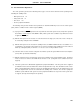
CHAPTER 7 CLOCK GENERATOR
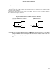
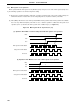
Figure 7-8. Examples of Oscillator with Bad Connection (2/2)
(c) Changing high current is too near a (d) Current flows through the grounding line
signal conductor of the oscillator (potential at points A, B,
and C fluctuate)
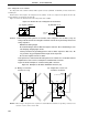
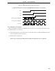
(e) Signals are fetched (f) Signal conductors of the main and sub-
system clock are parallel and near
each other
Remark When using a subsystem clock, replace X1 and X2 with XT1 and XT2, respectively. Also, insert
resistors in series on the XT2 side.
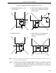
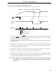
Cautions 2. In Figure 7-8 (f), XT2 and X1 are wired in parallel. Thus, the cross-talk noise of X1 may
increase with XT2, resulting in malfunctioning. To prevent that from occurring, it is
recommended to wire XT2 and X1 so that they are not in parallel, and to connect the IC
pin between XT1 and X1 directly to V
SS
.
IC X2 X1
High
Current
IC X2
AB C
Pnm
V
DD
High
Current
X1
IC X2 X1
IC X2 X1 XT1 XT2
XT1 and XT2 are wiring in parallel