
Single-Chip Microcontrollers User's Manual


488
CHAPTER 20 SERIAL INTERFACE CHANNEL 2
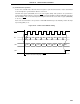
When the internal clock is used as the serial clock in the 3-wire serial I/O mode, set BRGC as described
below. BRGC Setting is not required if an external serial clock is used.
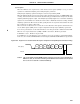
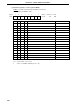
(i) When the baud rate generator is not used:
Select a serial clock frequency with TPS0 through TPS3. Be sure then to set MDL0 through MDL3 to
1,1,1,1.
The serial clock frequency becomes 1/2 of the source clock frequency for the 5-bit counter.
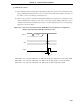
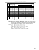
(ii) When the baud rate generator is used:
Select a serial clock frequency with MDL0 through MDL3 and TPS0 through TPS3. Be sure then to
set MDL0 through MDL3 to 1,1,1,1.
The serial clock frequency is calculated by the following formula.
f
XX
Serial clock frequency =
——————
[Hz]
2
n
x (k + 16)
fX : Main system clock oscillation frequency
fXX : Main system clock frequency (fX or fX/2)
n : Value set in TPS0 to TPS3 (1 ≤ n ≤ 11)
k : Value set in MDL0 to MDL3 (0 ≤ k ≤ 14)