
Electronics America Computer Hardware User Manual


130
µ
PD78214 Sub-Series
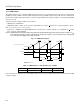
Fig. 7-25 Setting of Control Registers for Interval Timer Operation (1)
(a) Timer control register 0 (TMC0)
(b) Capture/compare control register 0 (CRC0)
76543210
000
0
00 0
1
CRC0
Disables clearing TM0
Both TO0 and TO1 are used for
toggle output
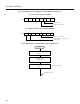
Fig. 7-26 Setting Procedure for Interval Timer Operation (1)
Interval
timer (1)
Set count value in CR00 register
Set CRC0 register
Start counting
; Sets bit 3 of TMC0 to 1
INTC00 interrupt
CR0←1
CRC0←10H
CR00←n
★
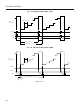
765
4
3
21
0
0
0
0
0
00
1
TMC0
Overflow flag
Enables counting TM0
×