
Electronics America Computer Hardware User Manual


134
µ
PD78214 Sub-Series
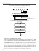
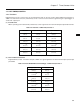
(c) External interrupt mode register 1 (INTM1)
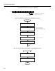
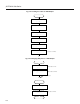
Fig. 7-33 Setting Procedure for Pulse Width Measurement
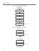
Fig. 7-34 Interrupt Request Handling for Pulse Width Calculation
Pulse width
measurement
Set CRC0 register
Set INTM1 register and
MK0L register
CRC0←10H
X
0←0
CE0←1
Initialize buffer memory for capture value
Start counting
; Sets bit 3 of TMC0 to 1
Enable interrupt
INTP3 interrupt
; Specifies valid edge of
INTP3 input to be both
edges and unmasks interrupt
INTP3 interrupt
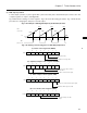
Calculation of pulse width
Store captured value in memory
Xn+1←CR02
RETI
Yn = CR02 – Xn
7
0
INTM1
0 × 11
6543210
×××
Specifies valid edge of INTP3 input
to be rising and falling edges
×
: Don't care