
Electronics America Computer Hardware User Manual

254
µ
PD78214 Sub-Series
9.5 BAUD RATE SETTING
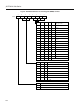
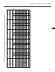
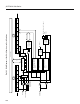
The baud rate can be set by three methods listed in Table 9-2.
The table indicates the ranges of baud rates that can be generated by each method, the baud rate calculation
formulas, and the selection methods.
Table 9-2 Baud Rate Setting
j
PRS3-PRS0 0H 1H 2H 3H 4H 5H 6H 7H
0 123456
Baud rate clock source
f
ASCK
2048
–
f
ASCK
Note
16
Selection method Calculation formula Baud rate range
×
2
n
×
1
16
f
ASCK
×
1
16
×
1
2m + 1
f
CLK
2
j + 3
SCK of the ASIM register = 08-bit timer/counter 3
ASCK input
MDL0 through MDL3 of
the BRGC register = FH
Baud rate
generator
for UART
Internal
system clock
SCK of the ASIM
register = 1
CE of the BRGC
register = 1
MDL0 through MDL3 of the
BRGC register = 0H to EH
f
CLK
61440
–
f
CLK
64
×
1
n
×
1
16
f
CLK
K + 1
–
f
CLK
256
f
CLK
4194304
f
CLK
: Internal system clock frequency
k : Value set in the MDL3 through MDL0 bits of the BRGC register (k = 1 through 14; see Fig. 9-9.)
1/n : Frequency divider tap (n = 2, 4, 8, 16, 32, 64, 128, 256)
f
ASCK
: Frequency of the ASCK input clock (0 – f
CLK
/24)
1/16 : Serial data sampling rate
j : Value set in the PRS3 through PRS0 bits of prescaler mode register 0 (j = 0 through 6)
m : Value set in the 8-bit compare register (CR30); m = 0 through 255
Note 0 – f
CLK
/384 if the f
ASCK
input range is included.
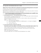
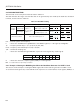
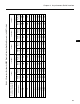
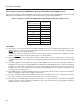
9.5.1 Example of Setting the BRGC Register When the Baud Rate Generator for UART Is Used
This section shows examples of setting the BRGC register when the baud rate generator for UART is used.
To use the baud rate generator, set the SCK bit of the asynchronous serial interface mode register (ASIM) to 1.