User’s Manual µPD789489 Subseries 8-Bit Single-Chip Microcontrollers µPD789488 µPD789489 µPD78F9488 µPD78F9489 Document No.
[MEMO] 2 User’s Manual U15331EJ4V1UD
NOTES FOR CMOS DEVICES 1 VOLTAGE APPLICATION WAVEFORM AT INPUT PIN Waveform distortion due to input noise or a reflected wave may cause malfunction. If the input of the CMOS device stays in the area between VIL (MAX) and VIH (MIN) due to noise, etc., the device may malfunction. Take care to prevent chattering noise from entering the device when the input level is fixed, and also in the transition period when the input level passes through the area between VIL (MAX) and VIH (MIN).
EEPROM and FIP are trademarks of NEC Electronics Corporation. Windows and Windows NT are either registered trademarks or trademarks of Microsoft Corporation in the United States and/or other countries. PC/AT is a trademark of International Business Machines Corporation. HP9000 series 700 and HP-UX are trademarks of Hewlett-Packard Company. SPARCstation is a trademark of SPARC International, Inc. Solaris and SunOS are trademarks of Sun Microsystems, Inc.
• The information in this document is current as of July, 2005. The information is subject to change without notice. For actual design-in, refer to the latest publications of NEC Electronics data sheets or data books, etc., for the most up-to-date specifications of NEC Electronics products. Not all products and/or types are available in every country. Please check with an NEC Electronics sales representative for availability and additional information.
Regional Information Some information contained in this document may vary from country to country. Before using any NEC Electronics product in your application, pIease contact the NEC Electronics office in your country to obtain a list of authorized representatives and distributors.
Major Revisions in This Edition Page Throughout Description Change of descriptions of µPD789489, 78F9489 • Change of status from under development to development completed • Change of the subseries name to “µPD789489 subseries” pp.31 to 33 Update of 1.5 78K/0S Series Lineup to latest version p.123 Modification of Figure 7-2 Block Diagram of Timer 50 p.124 Modification of Figure 7-3 Block Diagram of Timer 60 p.
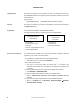
INTRODUCTION Target Readers This manual is intended for user engineers who wish to understand the functions of the µPD789489 Subseries and design and develop application systems and programs for these devices. Target products: • µPD789489 Subseries: Purpose µPD789488, 789489, 78F9488, 78F9489 This manual is intended to give users an understanding of the functions described in the Organization below.
Conventions Data significance: Higher digits on the left and lower digits on the right Active low representation: xxx (overscore over pin or signal name) Note: Footnote for item marked with Note in the text Caution: Information requiring particular attention Remark: Supplementary information Numerical representation: Binary ... xxxx or xxxxB Decimal ... xxxx Hexadecimal ... xxxxH Related Documents The related documents indicated in this publication may include preliminary versions.
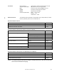
Documents Related to Flash Memory Writing Document Name Document No. PG-FP3 Flash Memory Programmer User’s Manual U13502E PG-FP4 Flash Memory Programmer User’s Manual U15260E Other Related Documents Document Name Document No.
CONTENTS CHAPTER 1 GENERAL .......................................................................................................................... 26 1.1 1.2 1.3 1.4 1.5 1.6 1.7 Features ...................................................................................................................................... 26 Applications ............................................................................................................................... 26 Ordering Information .................
3.1.4 3.2 3.3 3.2.1 Control registers............................................................................................................................ 58 3.2.2 General-purpose registers............................................................................................................. 61 3.2.3 Special function registers (SFRs).................................................................................................. 62 Instruction Address Addressing ......................
5.5 5.6 5.4.5 When subsystem clock is not used ............................................................................................. 104 5.4.6 Subsystem clock ×4 multiplication circuit .................................................................................... 104 Clock Generator Operation.....................................................................................................105 Changing Setting of System Clock and CPU Clock ................................................
9.4.1 Operation as watchdog timer ...................................................................................................... 171 9.4.2 Operation as interval timer .......................................................................................................... 172 CHAPTER 10 10-BIT A/D CONVERTER ............................................................................................173 10.1 10.2 10.3 10.4 10-Bit A/D Converter Functions...........................................
14.1 14.2 14.3 14.4 Multiplier Function...................................................................................................................267 Multiplier Configuration ..........................................................................................................267 Multiplier Control Register......................................................................................................269 Multiplier Operation ................................................................
CHAPTER 20 MASK OPTIONS ...........................................................................................................331 CHAPTER 21 INSTRUCTION SET ......................................................................................................332 21.1 Operation ..................................................................................................................................332 21.1.1 Operand identifiers and description methods ...........................................
LIST OF FIGURES (1/6) Figure No. 2-1 Title Page I/O Circuit Types ..........................................................................................................................................46 3-1 Memory Map (µPD789488) ..........................................................................................................................48 3-2 Memory Map (µPD78F9488)......................................................................................................................
LIST OF FIGURES (2/6) Figure No. Title Page 5-5 Format of Subclock Control Register............................................................................................................99 5-6 Subclock Selection Register Format ..........................................................................................................100 5-7 External Circuit of Main System Clock Oscillator........................................................................................
LIST OF FIGURES (3/6) Figure No. Title Page 7-21 Timing of Square-Wave Output with 16-Bit Resolution ..............................................................................149 7-22 Timing of Carrier Generator Operation (When CR60 = N, CRH60 = M (M > N))........................................151 7-23 Timing of Carrier Generator Operation (When CR60 = N, CRH60 = M (M < N))........................................152 7-24 Timing of Carrier Generator Operation (When CR60 = CRH60 = N) .........
LIST OF FIGURES (4/6) Figure No. Title Page 11-4 Format of Asynchronous Serial Interface Mode Register 20 ......................................................................191 11-5 Format of Asynchronous Serial Interface Status Register 20 .....................................................................193 11-6 Format of Baud Rate Generator Control Register 20 .................................................................................
LIST OF FIGURES (5/6) Figure No. Title Page 13-12 Four-Time-Slice LCD Display Pattern and Electrode Connections ............................................................263 13-13 Example of Connecting Four-Time-Slice LCD Panel .................................................................................264 13-14 Four-Time-Slice LCD Drive Waveform Examples (1/3 Bias Method) .........................................................265 13-15 Example of Connecting Pins for LCD Driver .........
LIST OF FIGURES (6/6) Figure No. Title Page 17-3 Releasing HALT Mode by RESET Input.....................................................................................................311 17-4 Releasing STOP Mode by Interrupt............................................................................................................313 17-5 Releasing STOP Mode by RESET Input ....................................................................................................
LIST OF TABLES (1/3) Table No. Title Page 2-1 Types of Pin I/O Circuits ..............................................................................................................................45 3-1 Internal ROM Capacity.................................................................................................................................52 3-2 Vector Table.................................................................................................................................
LIST OF TABLES (2/3) Table No. Title Page 10-1 Configuration of 10-Bit A/D Converter ........................................................................................................173 11-1 Configuration of Serial Interface 20 ............................................................................................................186 11-2 Serial Interface 20 Operation Mode Settings..............................................................................................
LIST OF TABLES (3/3) Table No. Title Page 21-1 Operand Identifiers and Description Methods ............................................................................................332 25-1 Surface Mounting Type Soldering Conditions ............................................................................................366 B-1 Distance Between IE System and Conversion Adapter..............................................................................
CHAPTER 1 GENERAL 1.1 Features • ROM and RAM capacities Item Data Memory Program Memory (ROM) Internal RAM LCD Display RAM Part Number µPD789488 Mask ROM µPD78F9488 Flash memory µPD789489 Mask ROM µPD78F9489 Flash memory 32 KB 1024 bytes 48 KB 1536 bytes 28 × 4 bits • Minimum instruction execution time can be selected from high speed (0.4 µs: @5.0 MHz operation with main system clock), low speed (1.6 µs: @5.0 MHz operation with main system clock), and ultra low speed (122 µs: @32.
CHAPTER 1 GENERAL 1.
CHAPTER 1 GENERAL 1.
CHAPTER 1 GENERAL Cautions 1. Connect the IC (Internally Connected) pin directly to VSS. 2. Connect the AVDD pin to VDD. 3. Connect the AVSS pin to VSS.
CHAPTER 1 GENERAL Notes 1. Whether to use these pins as input port pins (P70 to P73) or segment outputs (S16 to S19) can be selected in 1-bit units by means of a mask option or port function register (refer to 4.3 (3) Port function registers and CHAPTER 20 MASK OPTIONS). 2. Whether to use these pins as I/O port pins (P80 to P87) or segment outputs (S20 to S27) can be selected in 1-bit units by means of a mask option or port function register (refer to 4.
CHAPTER 1 GENERAL 1.5 78K/0S Series Lineup The products in the 78K/0S Series are listed below. The names enclosed in boxes are subseries names. Products in mass production Products under development Y Subseries products support SMB. Small-scale package, general-purpose applications 44-pin 42-/44-pin 30-pin 30-pin 20-pin 20-pin µ PD789074 with added subsystem clock µ PD789046 µ PD789026 µ PD789088 µ PD789074 µ PD789062 µ PD789052 On-chip UART and capable of low voltage (1.
CHAPTER 1 GENERAL The major functional differences between the subseries are listed below. Series for General-purpose applications and LCD drive Function ROM Capacity 8-Bit 16-Bit Watc WDT Subseries Name Small-scale µPD789046 package, generalpurpose µPD789026 µPD789088 8-Bit 10-Bit Timer A/D A/D Serial I/O Interface 1 ch 1 ch Value 1 ch − − 1 ch 34 − 1.8 V (UART: 1 ch) − 4 KB to 16 KB 16 KB to 1 ch Remarks MIN.
CHAPTER 1 GENERAL Series for ASSP Function ROM Capacity Timer 8-Bit 16-Bit Watc WDT µPD789800 A/D A/D Serial I/O Interface 8 KB 2 ch − − VDD Remarks MIN. h Subseries Name USB 8-Bit 10-Bit Value 1 ch − − 2 ch 31 4.0 V − 30 4.0 V − 31 4.
CHAPTER 1 GENERAL 1.
CHAPTER 1 GENERAL 1.7 Overview of Functions (1/2) µPD789488 Item Internal memory ROM 32 KB High-speed RAM 1024 bytes 32 KB (flash memory) − Low-speed RAM LCD display RAM µPD78F9488 µPD789489 48 KB µPD78F9489 48 KB (flash memory) 512 bytes 28 bytes Main system clock (oscillation frequency) Ceramic/crystal oscillation (1.0 to 5.0 MHz) Subsystem clock (oscillation frequency) Crystal oscillation (32.768 kHz) Minimum instruction execution time 0.4 µs/1.6 µs (@5.
CHAPTER 1 GENERAL (2/2) µPD789488 Item µPD78F9488 Supply voltage VDD = 1.8 to 5.5 V Operating ambient temperature TA = −40 to +85°C Package • 80-pin plastic QFP (14 × 14) µPD789489 µPD78F9489 • 80-pin plastic TQFP (fine pitch) (12 × 12) An outline of the timer is shown below.
CHAPTER 2 PIN FUNCTIONS 2.1 List of Pin Functions (1) Port pins (1/2) Pin Name P00 to P07 I/O I/O Function Port 0. After Reset Input 8-bit I/O port. Alternate Function KR0 to KR7 Note 1 KR00 to KR07 Note 2 Input/output can be specified in 1-bit units. When used as an input port, an on-chip pull-up resistor can be specified in 1-bit units by pull-up resistor option register B0 (PUB0) or the key return mode register (KRM00). P10, P11 I/O Port 1. − Input 2-bit I/O port.
CHAPTER 2 PIN FUNCTIONS (1) Port pins (2/2) Pin Name I/O Function After Reset Alternate Function P70 to P73 Note 1 Input Port 7. 4-bit input port. (Only when input port is selected by mask option or port function register) Input − P80 to P87 Note 2 I/O Port 8. 8-bit I/O port. (Only when I/O port is selected by mask option or port function register) Input − Notes 1.
CHAPTER 2 PIN FUNCTIONS (2) Non-port pins (2/2) Pin Name I/O S0 to S15 Function Output LCD controller/driver segment signal outputs After Reset Low-level output Alternate Function – S16 to S19 Note 1 Only when segment output is selected by mask option – S20 to S27 Note 2 Only when segment output is selected by mask option – COM0 to COM3 Output LCD controller/driver common signal outputs VLC0 to VLC2 – Low-level output LCD drive voltage – CAPH, CAPL − LCD drive voltage booster capaci
CHAPTER 2 PIN FUNCTIONS 2.2 Description of Pin Functions 2.2.1 P00 to P07 (Port 0) These pins constitute an 8-bit I/O port. In addition, these pins enable key return signal detection. Port 0 can be specified in the following operation modes in 1-bit units. (1) Port mode These pins constitute an 8-bit I/O port and can be set in the input or output port mode in 1-bit units by port mode register 0 (PM0).
CHAPTER 2 PIN FUNCTIONS 2.2.4 P30 to P34 (Port 3) These pins constitute a 5-bit I/O port. In addition, they also function as timer I/O, external interrupt input, and remote control receive data input Note . Port 3 can be specified in the following operation modes in 1-bit units. (1) Port mode In this mode, P30 to P34 function as a 5-bit I/O port. Port 3 can be set in the input or output port mode in 1bit units by port mode register 3 (PM3).
CHAPTER 2 PIN FUNCTIONS 2.2.6 P60 to P67 (Port 6) This is an 8-bit input-only port. In addition to a general-purpose input port function, it has A/D converter input and Note key return signal detection (1) functions. Port mode In this mode, P60 to P67 function as an 8-bit input-only port. (2) Control mode In this mode, P60 to P67 function as the analog inputs of the A/D converter and key return signal detection pins (a) Note . ANI0 to ANI7 These are the analog input pins of the A/D converter.
CHAPTER 2 PIN FUNCTIONS 2.2.13 RESET This pin inputs an active-low system reset signal. 2.2.14 X1, X2 These pins are used to connect a crystal resonator for main system clock oscillation. To supply an external clock, input the clock to X1 and input the inverted signal to X2. 2.2.15 XT1, XT2 These pins are used to connect a crystal resonator for subsystem clock oscillation. To supply an external clock, input the clock to XT1 and input the inverted signal to XT2. 2.2.
CHAPTER 2 PIN FUNCTIONS 2.2.21 IC0 (mask ROM version only) The IC0 (Internally Connected) pin is used to set the µPD789489 Subseries in the test mode before shipment. In the normal operation mode, directly connect this pin to the VSS pin with as short a wiring length as possible. If there is a potential difference between the IC0 pin and VSS pin due to a long wiring length or external noise superimposed on the IC0 pin, the user program may not run correctly. • Directly connect the IC0 pin to the VSS pin.
CHAPTER 2 PIN FUNCTIONS 2.3 Pin I/O Circuits and Recommended Connection of Unused Pins The I/O circuit type of each pin and recommended connection of unused pins are shown in Table 2-1. For the I/O circuit configuration of each type, see Figure 2-1. Table 2-1. Types of Pin I/O Circuits (1/2) Pin Name P00/KR0 to P07/KR7 Note 1 I/O Circuit Type I/O 8-A I/O Recommended Connection of Unused Pins Input: Independently connect to VDD or VSS via a resistor. Output: Leave open.
CHAPTER 2 PIN FUNCTIONS Table 2-1. Types of Pin I/O Circuits (2/2) Pin Name I/O Circuit Type I/O – Input XT1 XT2 – RESET 2 Input IC0 – – VPP Recommended Connection of Unused Pins Connect to VSS. Leave open. – Connect directly to VSS. Independently connect a 10 kΩ pull-down resistor, or connect directly to VSS. Figure 2-1. I/O Circuit Types (1/2) Type 2 Type 2-H IN IN Input enable Schmitt-triggered input with hysteresis characteristics.
CHAPTER 2 PIN FUNCTIONS Figure 2-1.
CHAPTER 3 CPU ARCHITECTURE 3.1 Memory Space The µPD789489 Subseries can access 64 KB of memory space. Figures 3-1 to 3-4 show the memory maps. Figure 3-1.
CHAPTER 3 CPU ARCHITECTURE Figure 3-2.
CHAPTER 3 CPU ARCHITECTURE Figure 3-3.
CHAPTER 3 CPU ARCHITECTURE Figure 3-4.
CHAPTER 3 CPU ARCHITECTURE 3.1.1 Internal program memory space The internal program memory space stores programs and table data. This space is usually addressed by the program counter (PC). The µPD789489 Subseries provide internal ROM (or flash memory) with the following capacity for each product. Table 3-1.
CHAPTER 3 CPU ARCHITECTURE 3.1.2 Internal data memory space (1) Internal high-speed RAM and internal low-speed RAM The µPD789489 Subseries products incorporate the internal high-speed RAM and internal low-speed RAM of the following capacity for each product. The internal high-speed RAM can also be used as a stack. The internal low-speed RAM cannot be used as a stack. Table 3-3.
CHAPTER 3 CPU ARCHITECTURE 3.1.4 Data memory addressing The µPD789489 Subseries is provided with a variety of addressing modes to make memory manipulation as efficient as possible. At the addresses corresponding to data memory area (FB00H to FFFFH) especially, specific addressing modes that correspond to the particular function of an area, such as the special function registers, are available. Figures 3-5 to 3-8 show the data memory addressing modes. Figure 3-5.
CHAPTER 3 CPU ARCHITECTURE Figure 3-6.
CHAPTER 3 CPU ARCHITECTURE Figure 3-7.
CHAPTER 3 CPU ARCHITECTURE Figure 3-8.
CHAPTER 3 CPU ARCHITECTURE 3.2 Processor Registers The µPD789489 Subseries is provided with the following on-chip processor registers. 3.2.1 Control registers The control registers contain special functions to control the program sequence status and stack memory. The program counter, program status word, and stack pointer are control registers. (1) Program counter (PC) The program counter is a 16-bit register that holds the address information of the next program to be executed.
CHAPTER 3 CPU ARCHITECTURE (a) Interrupt enable flag (IE) This flag controls interrupt request acknowledgement operations of the CPU. When 0, IE is set to the interrupt disabled status (DI), and interrupt requests other than non-maskable interrupts are all disabled. When 1, IE is set to the interrupt enabled status (EI). Interrupt request acknowledgement enable is controlled by the interrupt mask flag for the corresponding interrupt source.
CHAPTER 3 CPU ARCHITECTURE (3) Stack pointer (SP) This is a 16-bit register that holds the start address of the memory stack area. Only the internal high-speed RAM area can be set as the stack area. Figure 3-11. Stack Pointer Configuration 15 0 SP SP15 SP14 SP13 SP12 SP11 SP10 SP9 SP8 SP7 SP6 SP5 SP4 SP3 SP2 SP1 SP0 The SP is decremented ahead of write (save) to the stack memory and is incremented after read (restore) from the stack memory.
CHAPTER 3 CPU ARCHITECTURE 3.2.2 General-purpose registers The general-purpose registers consist of eight 8-bit registers (X, A, C, B, E, D, L, and H). Each register can be used as an 8-bit register, or two 8-bit registers in pairs can be used as a 16-bit register (AX, BC, DE, and HL). General-purpose registers can be described in terms of function names (X, A, C, B, E, D, L, H, AX, BC, DE, or HL) or absolute names (R0 to R7 and RP0 to RP3). Figure 3-14.
CHAPTER 3 CPU ARCHITECTURE 3.2.3 Special function registers (SFRs) Unlike a general-purpose register, each special function register has a special function. The special function registers are allocated in the 256-byte area of FF00H to FFFFH. Special function registers can be manipulated, like general-purpose registers, by operation, transfer, and bit manipulation instructions. The manipulatable bit units (1, 8, and 16) differ depending on the special function register type.
CHAPTER 3 CPU ARCHITECTURE Table 3-4.
CHAPTER 3 CPU ARCHITECTURE Table 3-4.
CHAPTER 3 CPU ARCHITECTURE Table 3-4.
CHAPTER 3 CPU ARCHITECTURE 3.3 Instruction Address Addressing An instruction address is determined by the program counter (PC) contents. The PC contents are normally incremented (+1 for each byte) automatically according to the number of bytes of an instruction to be fetched each time another instruction is executed.
CHAPTER 3 CPU ARCHITECTURE 3.3.2 Immediate addressing [Function] Immediate data in the instruction word is transferred to the program counter (PC) and branched. This function is carried out when the CALL !addr16 or BR !addr16 instruction is executed. CALL !addr16 and BR !addr16 instructions can be branched to any location in the memory space. [Illustration] In case of CALL !addr16 and BR !addr16 instructions 7 0 CALL or BR Low Addr. High Addr.
CHAPTER 3 CPU ARCHITECTURE 3.3.3 Table indirect addressing [Function] Table contents (branch destination address) of the particular location to be addressed by the lower 5-bit immediate data of an instruction code from bit 1 to bit 5 are transferred to the program counter (PC) and branched. This function is carried out when the CALLT [addr5] instruction is executed. The instruction enables a branch to any location in the memory space by referring to the addresses stored in the memory table at 40H to 7FH.
CHAPTER 3 CPU ARCHITECTURE 3.4 Operand Address Addressing The following various methods are available to specify the register and memory (addressing) which undergo manipulation during instruction execution. 3.4.1 Direct addressing [Function] The memory indicated with immediate data in an instruction word is directly addressed.
CHAPTER 3 CPU ARCHITECTURE 3.4.2 Short direct addressing [Function] The memory to be manipulated in the fixed space is directly addressed with 8-bit data in an instruction word. The fixed space is the 256-byte space FE20H to FF1FH where the addressing is applied. Internal high-speed RAM and special function registers (SFRs) are mapped at FE20H to FEFFH and FF00H to FF1FH, respectively. The SFR area (FF00H to FF1FH) where short direct addressing is applied is a part of the whole SFR area.
CHAPTER 3 CPU ARCHITECTURE 3.4.3 Special function register (SFR) addressing [Function] The memory-mapped special function registers (SFRs) are addressed with 8-bit immediate data in an instruction word. This addressing is applied to the 256-byte space FF00H to FFFFH. However, the SFRs mapped at FF00H to FF1FH can also be accessed with short direct addressing.
CHAPTER 3 CPU ARCHITECTURE 3.4.4 Register addressing [Function] In the register addressing mode, general-purpose registers are accessed as operands. The general-purpose register to be accessed is specified by a register specification code or functional name in the instruction code. Register addressing is carried out when an instruction with the following operand format is executed. When an 8-bit register is specified, one of the eight registers is specified with 3 bits in the instruction code.
CHAPTER 3 CPU ARCHITECTURE 3.4.5 Register indirect addressing [Function] In the register indirect addressing mode, memory is manipulated according to the contents of a register pair specified as an operand. The register pair to be accessed is specified by the register pair specification code in an instruction code. This addressing can be carried out for all the memory spaces.
CHAPTER 3 CPU ARCHITECTURE 3.4.6 Based addressing [Function] 8-bit immediate data is added to the contents of the base register, that is, the HL register pair, and the sum is used to address the memory. Addition is performed by expanding the offset data as a positive number to 16 bits. A carry from the 16th bit is ignored. This addressing can be carried out for all the memory spaces.
CHAPTER 4 PORT FUNCTIONS 4.1 Port Functions The µPD789489 Subseries provides the ports shown in Figure 4-1, enabling various methods of control. The functions of each port are shown in Table 4-1. Numerous other functions are provided that can be used in addition to the digital I/O port functions. For more information on these additional functions, see CHAPTER 2 PIN FUNCTIONS. Figure 4-1.
CHAPTER 4 PORT FUNCTIONS Table 4-1. Port Functions Port Name Pin Name Port 0 P00 to P07 Function I/O port. Input/output can be specified in 1-bit units. When used as an input port, an on-chip pull-up resistor can be specified in 1-bit units by pull-up resistor option register B0 (PUB0) or the key return mode register (KRM00). Port 1 P10, P11 I/O port. Input/output can be specified in 1-bit units.
CHAPTER 4 PORT FUNCTIONS 4.2.1 Port 0 This is an 8-bit I/O port with an output latch. Port 0 can be specified in the input or output mode in 1-bit units by using port mode register 0 (PM0). When the P00 to P07 pins are used as input port pins, on-chip pull-up resistors can be connected in 1-bit units by using pull-up resistor option register B0 (PUB0). This port is also used for key return signal input. RESET input sets this port to input mode. Figure 4-2 shows a block diagram of port 0. Figure 4-2.
CHAPTER 4 PORT FUNCTIONS 4.2.2 Port 1 This is a 2-bit I/O port with an output latch. Port 1 can be specified in the input or output mode in 1-bit units by using port mode register 1 (PM1). When using the P10 and P11 pins as input port pins, on-chip pull-up resistors can be connected in 1-bit units by using pull-up resistor option register B1 (PUB1). RESET input sets this port to input mode. Figure 4-3 shows a block diagram of port 1. Figure 4-3.
CHAPTER 4 PORT FUNCTIONS 4.2.3 Port 2 This is a 6-bit I/O port with an output latch. Port 2 can be specified in the input or output mode in 1-bit units by using port mode register 2 (PM2). When using the P20 to P25 pins as input port pins, on-chip pull-up resistors can be connected in 1-bit units by using pull-up resistor option register B2 (PUB2). This port is also used for serial interface I/O. RESET input sets this port to input mode. Figures 4-4 to 4-8 show block diagrams of port 2.
CHAPTER 4 PORT FUNCTIONS Figure 4-5.
CHAPTER 4 PORT FUNCTIONS Figure 4-6.
CHAPTER 4 PORT FUNCTIONS Figure 4-7.
CHAPTER 4 PORT FUNCTIONS Figure 4-8.
CHAPTER 4 PORT FUNCTIONS 4.2.4 Port 3 This is a 5-bit I/O port with an output latch. Port 3 can be specified in the input or output mode in 1-bit units by using port mode register 3 (PM3). When using the P30 to P34 pins as input port pins, on-chip pull-up resistors can be connected in 1-bit units by using pull-up resistor option register B3 (PUB3). This port is also used for external interrupt input, capture input, timer I/O, and remote control receive data inputNote.
CHAPTER 4 PORT FUNCTIONS Figure 4-10.
CHAPTER 4 PORT FUNCTIONS 4.2.5 Port 5 This is a 4-bit N-ch open-drain I/O port with an output latch. Port 5 can be specified in the input or output mode in 1-bit units by using port mode register 5 (PM5). For a mask ROM version, use of an on-chip pull-up resistor can be specified by a mask option. RESET input sets this port to input mode. Figure 4-11 shows a block diagram of port 5. Figure 4-11.
CHAPTER 4 PORT FUNCTIONS 4.2.6 Port 6 This is an 8-bit input-only port. Note This port is also used for the analog input of an A/D converter and key return signal input . Figure 4-12 shows a block diagram of port 6. Note µPD789489 and 78F9489 only. Figure 4-12.
CHAPTER 4 PORT FUNCTIONS Figure 4-12.
CHAPTER 4 PORT FUNCTIONS 4.2.7 Port 7 This is a 4-bit input-only port. Only the bits for which the port function is selected can be used, by using a mask option in the µPD789488 and 789489 or port function register 7 (PF7) in the µPD78F9488 and 78F9489. Figure 4-13 shows a block diagram of port 7. Figure 4-13.
CHAPTER 4 PORT FUNCTIONS 4.2.8 Port 8 This is an 8-bit I/O port with an output latch. Only the bits for which the port function is selected can be used, by using a mask option in the µPD789488 and 789489 or port function register 8 (PF8) in the µPD78F9488 and 78F9489. Port 8 can be specified in the input or output mode in 1-bit units by using port mode register 8 (PM8). RESET input sets this port to input mode. Figure 4-14 shows a block diagram of port 8. Figure 4-14.
CHAPTER 4 PORT FUNCTIONS 4.3 Registers Controlling Port Function The ports are controlled by the following three types of registers. • Port mode registers (PM0 to PM3, PM5, PM8) • Pull-up resistor option registers (PUB0 to PUB3) • Port function registers (PF7, PF8) (µPD78F9488, 78F9489 only) (1) Port mode registers (PM0 to PM3, PM5, PM8) Input and output can be specified in 1-bit units. These registers can be set with a 1-bit or 8-bit memory manipulation instruction.
CHAPTER 4 PORT FUNCTIONS Table 4-3.
CHAPTER 4 PORT FUNCTIONS (2) Pull-up resistor option registers (PUB0 to PUB3) These registers set whether to use on-chip pull-up resistors for pins P00 to P07, P10, P11, P20 to P25, and P30 to P34. An on-chip pull-up resistor can be used only for those bits set to the input mode in a port for which the use of the on-chip pull-up resistor has been specified using PUB0 to PUB3. For those bits set to the output mode, on-chip pull-up resistors cannot be used, regardless of the setting of PUB0 to PUB3.
CHAPTER 4 PORT FUNCTIONS 4.4 Port Function Operation The operation of a port differs depending on whether the port is set in the input or output mode, as described below. 4.4.1 Writing to I/O port (1) In output mode A value can be written to the output latch of a port by using a transfer instruction. The contents of the output latch can be output from the pins of the port. Once data is written to the output latch, it is retained until new data is written to the output latch.
CHAPTER 5 CLOCK GENERATOR 5.1 Clock Generator Functions The clock generator generates the clock to be supplied to the CPU and peripheral hardware. The following two types of system clock oscillators are used. • Main system clock oscillator This circuit oscillates at 1.0 to 5.0 MHz. Oscillation can be stopped by executing the STOP instruction or setting the processor clock control register (PCC). • Subsystem clock oscillator This circuit oscillates at 32.768 kHz.
CHAPTER 5 CLOCK GENERATOR Figure 5-1.
CHAPTER 5 CLOCK GENERATOR Figure 5-2.
CHAPTER 5 CLOCK GENERATOR 5.3 Registers Controlling Clock Generator The clock generator is controlled by the following four registers. • Processor clock control register (PCC) • Subclock oscillation mode register (SCKM) • Subclock control register (CSS) • Subclock selection register (SSCK) (µPD78F9488, 78F9489 only) (1) Processor clock control register (PCC) This register is used to select the CPU clock and set the frequency division ratio. PCC is set with a 1-bit or 8-bit memory manipulation instruction.
CHAPTER 5 CLOCK GENERATOR (2) Subclock oscillation mode register (SCKM) SCKM selects a feedback resistor for the subsystem clock, and controls the oscillation of the clock. SCKM is set with a 1-bit or 8-bit memory manipulation instruction. RESET input sets SCKM to 00H. Figure 5-4.
CHAPTER 5 CLOCK GENERATOR (4) Subclock selection register (SSCK) (µPD78F9488, 78F9489 only) This register is used to control the operation of the ×4 subsystem clock multiplication circuit. SSCK is set via a 1-bit or 8-bit memory manipulation instruction. RESET input sets this register to 00H. Caution This register is valid only in the µPD78F9488 and 78F9489; however, writing to it in the µPD789488 and 789489 will simply make it invalid, causing no operational effect. Figure 5-6.
CHAPTER 5 CLOCK GENERATOR 5.4 System Clock Oscillators 5.4.1 Main system clock oscillator The main system clock oscillator is oscillated by the crystal or ceramic resonator (5.0 MHz TYP.) connected across the X1 and X2 pins. An external clock can also be input to the circuit. In this case, input the clock signal to the X1 pin, and input the inverted signal to the X2 pin. Figure 5-7 shows the external circuit of the main system clock oscillator. Figure 5-7.
CHAPTER 5 CLOCK GENERATOR 5.4.2 Subsystem clock oscillator The subsystem clock oscillator is oscillated by the crystal resonator (32.768 kHz TYP.) connected across the XT1 and XT2 pins. An external clock can also be input to the circuit. In this case, input the clock signal to the XT1 pin, and input the inverted signal to the XT2 pin. Figure 5-8 shows the external circuit of the subsystem clock oscillator. Figure 5-8.
CHAPTER 5 CLOCK GENERATOR 5.4.3 Example of incorrect resonator connection Figure 5-9 shows examples of incorrect resonator connection. Figure 5-9.
CHAPTER 5 CLOCK GENERATOR Figure 5-9. Examples of Incorrect Resonator Connection (2/2) (e) Signal is fetched VSS Remark X1 X2 When using the subsystem clock, read X1 and X2 as XT1 and XT2, respectively, and connect a resistor to XT2 in series. 5.4.4 Divider circuit The divider circuit divides the output of the main system clock oscillator (fX) to generate various clocks. 5.4.
CHAPTER 5 CLOCK GENERATOR 5.5 Clock Generator Operation The clock generator generates the following clocks and controls the operation modes of the CPU, such as the standby mode. • Main system clock • Subsystem clock • CPU clock fX fXT fCPU • Clock to peripheral hardware The operation and function of the clock generator is determined by the processor clock control register (PCC), subclock oscillation mode register (SCKM), and subclock control register (CSS), as follows. (a) The low-speed mode (1.
CHAPTER 5 CLOCK GENERATOR 5.6 Changing Setting of System Clock and CPU Clock 5.6.1 Time required for switching between system clock and CPU clock The CPU clock can be selected by using bit 1 (PCC1) of the processor clock control register (PCC) and bit 4 (CSS0) of the subclock control register (CSS). Actually, the specified clock is not selected immediately after the setting of PCC has been changed; the old clock is used for the duration of several instructions after that (see Table 5-2). Table 5-2.
CHAPTER 5 CLOCK GENERATOR 5.6.2 Switching between system clock and CPU clock The following figure illustrates how the CPU clock and system clock switch. Figure 5-10. Switching Between System Clock and CPU Clock VDD RESET Interrupt request signal System clock CPU clock fX fX Low-speed operation High-speed operation fXT fX Subsystem clock operation High-speed operation Wait (6.55 ms: at 5.
CHAPTER 6 16-BIT TIMER 20 6.1 16-Bit Timer 20 Functions 16-bit timer 20 has the following functions. • Timer interrupt • Timer output • Count value capture (1) Timer interrupt An interrupt is generated when a count value and compare value match. (2) Timer output Timer output can be controlled when a count value and compare value match. (3) Count value capture The count value of 16-bit timer counter 20 (TM20) is latched into a capture register in synchronization with the capture trigger and retained.
CHAPTER 6 16-BIT TIMER 20 Figure 6-1.
CHAPTER 6 16-BIT TIMER 20 (4) 16-bit counter read buffer 20 This buffer is used to latch and hold the count value for TM20. 6.3 Registers Controlling 16-Bit Timer 20 16-bit timer 20 is controlled by the following three registers. • 16-bit timer mode control register 20 (TMC20) • Port mode register 3 (PM3) • Port 3 (P3) (1) 16-bit timer mode control register 20 (TMC20) 16-bit timer mode control register 20 (TMC20) controls the setting of the count clock, capture edge, etc.
CHAPTER 6 16-BIT TIMER 20 Figure 6-2.
CHAPTER 6 16-BIT TIMER 20 (2) Port mode register 3 (PM3) This register is used to set the I/O mode of port 3 in 1-bit units. When using the P33/INTP3/CPT20/TO20 pin as a capture input (CPT20), set PM33 to 1. When using the above pin as a timer output (TO20), set the PM33 and P33 output latches to 0. PM3 is set with a 1-bit or 8-bit memory manipulation instruction. RESET input sets this register to FFH. Figure 6-3.
CHAPTER 6 16-BIT TIMER 20 6.4 16-Bit Timer 20 Operation 6.4.1 Operation as timer interrupt 16-bit timer 20 can generate interrupts repeatedly each time the free-running counter value reaches the value set to CR20. Since this counter is not cleared and holds the count even after an interrupt is generated, the interval time is equal to one cycle of the count clock set in TCL201 and TCL200. To operate 16-bit timer 20 as a timer interrupt, the following settings are required.
CHAPTER 6 16-BIT TIMER 20 Figure 6-5.
CHAPTER 6 16-BIT TIMER 20 6.4.2 Operation as timer output 16-bit timer 20 can invert the timer output repeatedly each time the free-running counter value reaches the value set to CR20. Since this counter is not cleared and holds the count even after the timer output is inverted, the interval time is equal to one cycle of the count clock set in TCL201 and TCL200. To operate 16-bit timer 20 as a timer output, the following settings are required. • Set P33 to output mode (PM33 = 0).
CHAPTER 6 16-BIT TIMER 20 6.4.3 Capture operation The capture operation consists of latching the count value of 16-bit timer counter 20 (TM20) into a capture register in synchronization with a capture trigger, and retaining the count value. Set TMC20 as shown in Figure 6-8 to allow the 16-bit timer to start the capture operation. Figure 6-8.
CHAPTER 6 16-BIT TIMER 20 6.4.4 16-bit timer counter 20 readout The count value of 16-bit timer counter 20 (TM20) is read out using a 16-bit manipulation instruction. TM20 readout is performed via the counter read buffer. The counter read buffer latches the TM20 count value, the buffer operation is held pending at the CPU clock falling edge after the read signal of the TM20 lower byte rises, and the count value is retained. The retained counter read buffer value can be read out as the count value.
CHAPTER 6 16-BIT TIMER 20 6.5 Cautions on Using 16-Bit Timer 20 6.5.1 Restrictions when rewriting 16-bit compare register 20 (1) Disable interrupts (TMMK20 = 1) and inversion control of timer output (TOC20 = 0) before rewriting the compare register (CR20). If the value in CR20 is rewritten in the interrupt-enabled state, an interrupt request may occur at the moment of rewrite.
CHAPTER 6 16-BIT TIMER 20 When rewriting using 16-bit access <1> Disable interrupts (TMMK20 = 1) and inversion control of timer output (TOC20 = 0). <2> Rewrite CR20 (16 bits). <3> Wait for one cycle or more of the count clock. <4> Clear the interrupt request flag (TMIF20). <5> Enable timer interrupts/timer output inversion (count clock = 32/fX, CPU clock = fX) TM20_VCT: SET1 TMMK20 ; Disable timer interrupts CLR1 TMC20.
CHAPTER 7 8-BIT TIMERS 50, 60, AND 61 7.1 Functions of 8-Bit Timers 50, 60, and 61 One 8-bit timer channel (timer 50) and two 8-bit timer/event counter channels (timer 60 and 61) are incorporated in the µPD789489 Subseries. The operation modes listed in the following table can be set via mode register settings. Table 7-1.
CHAPTER 7 8-BIT TIMERS 50, 60, AND 61 (5) PPG output mode (PPG: Programmable Pulse Generator) Pulses are output using any cycle or duty ratio (pulse width) set (both the cycle and pulse width are programmable). (6) 24-bit event counter mode Operation as an external event counter with 24-bit resolution is enabled using 16-bit timer 20 and timer 61. However, this mode operates only as a counter read function. There is no compare, match, or clear function.
CHAPTER 7 8-BIT TIMERS 50, 60, AND 61 7.2 Configuration of 8-Bit Timers 50, 60, and 61 8-bit timers 50, 60, and 61 include the following hardware. Table 7-2.
Figure 7-2.
Figure 7-3.
Figure 7-4.
CHAPTER 7 8-BIT TIMERS 50, 60, AND 61 Figure 7-5. Block Diagram of Output Controller (Timer 60) TOE60 RMC60 NRZ60 Selector P31 output latch F/F PM31 TO60/INTP1/P31 Carrier clock Carrier generator mode (1) 8-bit compare register 50 (CR50) This 8-bit register is used to continually compare the value set to CR50 with the count value in 8-bit timer counter 50 (TM50) and to issue an interrupt request (INTTM50) when a match occurs. In PWM mode, this register is used for high-level width setting.
CHAPTER 7 8-BIT TIMERS 50, 60, AND 61 (4) 8-bit H width compare registers 60 and 61 (CRH60, CRH61) In carrier generator mode and PPG output mode, the high-level width of timer output is set by writing a value to CRH6n. This 8-bit register is used to continually compare the value set to CRH6n with the count value in 8-bit timer counter 6n (TM6n) and to issue an interrupt request (INTTM6n) when a match occurs. CRH6n is set with an 8-bit memory manipulation instruction.
CHAPTER 7 8-BIT TIMERS 50, 60, AND 61 7.3 Control Registers for 8-Bit Timers 50, 60, and 61 8-bit timers 50, 60, and 61 are controlled by the following six registers.
CHAPTER 7 8-BIT TIMERS 50, 60, AND 61 Figure 7-6. Format of 8-Bit Timer Mode Control Register 50 (2/2) Symbol <7> <6> 5 4 3 2 1 <0> Address After reset R/W TMC50 TCE50 TEG50 TCL502 TCL501 TCL500 TMD501 TMD500 TOE50 FF4DH 00H R/W TOE50 Control of timer output 0 Output disabled 1 Output enabled Note 4 Notes 1. Since the count operation is controlled by TCE60 (bit 7 of TMC60) in cascade connection mode, any setting for TCE50 is ignored. 2.
CHAPTER 7 8-BIT TIMERS 50, 60, AND 61 Figure 7-7.
CHAPTER 7 8-BIT TIMERS 50, 60, AND 61 (3) Carrier generator output control register 60 (TCA60) This register is used to set the timer output data in carrier generator mode. TCA60 is set with a 1-bit or 8-bit memory manipulation instruction. RESET input sets this register to 00H. Figure 7-8.
CHAPTER 7 8-BIT TIMERS 50, 60, AND 61 (4) 8-bit timer mode control register 61 (TMC61) 8-bit timer mode control register 61 (TMC61) is used to control the timer 61 count clock setting and the operation mode setting. TMC61 is set with a 1-bit or 8-bit memory manipulation instruction. RESET input sets this register to 00H. Figure 7-9.
CHAPTER 7 8-BIT TIMERS 50, 60, AND 61 (5) Port mode register 3 (PM3) This register is used to set the I/O mode of port 3 in 1-bit units. When using the P30/INTP0/TO50/TMI60 pin as a timer output (TO50), set PM30 and the P30 output latch to 0. When used as a timer input (TMI60), set PM30 to 1. When using the P31/INTP1/TO60 pin as a timer output (TO60), set PM31 and the P31 output latch to 0. When using the P32/INTP2/TO61/TMI61 pin as a timer input (TMI61), set PM32 to 1.
CHAPTER 7 8-BIT TIMERS 50, 60, AND 61 7.4 Operation of 8-Bit Timers 50, 60, and 61 7.4.1 Operation as 8-bit timer counter Timer 50, timer 60, and timer 61 can be independently used as 8-bit timer counters. The following modes can be used for the 8-bit timer counter.
CHAPTER 7 8-BIT TIMERS 50, 60, AND 61 Table 7-3. Interval Time of Timer 50 TCL502 TCL501 TCL500 0 0 0 Minimum Interval Time 1/fX (0.2 µs) Maximum Interval Time Resolution 8 1/fX (0.2 µs) 11 2 /fX (1.6 µs) 15 2 /fX (25.6 µs) 8 2 /fX (51.2 µs) 3 2 /fX (409.6 µs) 7 3 0 0 1 2 /fX (1.6 µs) 0 1 0 2 /fX (25.6 µs) 2 /fX (6.55 ms) 0 1 1 1/fXT (30.5 µs) 2 /fXT (7.81 ms) 1/fXT (30.
CHAPTER 7 8-BIT TIMERS 50, 60, AND 61 Figure 7-11. Timing of Interval Timer Operation with 8-Bit Resolution (Basic Operation) t Count clock TMnm 00H 01H N 00H 01H 00H N Clear 01H N Clear 00H 01H 00H Clear N CRnm TCEnm Count start Count stop INTTMnm Interrupt acknowledgement Interrupt acknowledgement Interval time Interval time Interrupt acknowledgement TOnm Remarks 1. Interval time = (N + 1) × t: N = 00H to FFH 2. nm = 50, 60, 61 Figure 7-12.
CHAPTER 7 8-BIT TIMERS 50, 60, AND 61 Figure 7-13. Timing of Interval Timer Operation with 8-Bit Resolution (When CRnm Is Set to FFH) Count clock TMnm 00H 01H FFH 01H 00H FFH Clear 00H 01H FFH Clear FFH 00H 00H Clear FFH CRnm TCEnm Count start INTTMnm TOnm Remark nm = 50, 60, 61 Figure 7-14.
CHAPTER 7 8-BIT TIMERS 50, 60, AND 61 Figure 7-15.
CHAPTER 7 8-BIT TIMERS 50, 60, AND 61 Figure 7-16.
CHAPTER 7 8-BIT TIMERS 50, 60, AND 61 (2) Operation as external event counter with 8-bit resolution (timer 60 and timer 61 only) The external event counter counts the number of external clock pulses input to the TMI6m pin by using 8-bit timer counter 6m (TM6m). To operate timer 6m as an external event counter, settings must be made in the following sequence. <1> Disable operation of 8-bit timer counter 6m (TM6m) (TCE6m = 0). <2> Disable timer output of TO6m (TOE6m0 = 0).
CHAPTER 7 8-BIT TIMERS 50, 60, AND 61 (3) Operation as square-wave output with 8-bit resolution Square waves of any frequency can be output at an interval specified by the value preset in 8-bit compare register nm (CRnm). To operate timer nm for square-wave output, settings must be made in the following sequence. <1> When using timer 50, set P30 to output mode (PM30 = 0) and the P30 output latch to 0, respectively.
CHAPTER 7 8-BIT TIMERS 50, 60, AND 61 Table 7-7. Square-Wave Output Range of Timer 60 TCL602 TCL601 0 TCL600 0 Minimum Pulse Width 1/fX (0.2 µs) 10 2 2 0 0 1 2 /fX (0.8 µs) 2 /fX (204 µs) 0 1 0 fTMI input cycle fTMI input cycle × 2 0 1 1 fTMI/2 input cycle fTMI/2 input cycle × 2 2 /fX (0.8 µs) 8 fTMI input cycle 8 2 fTMI/2 input cycle × 2 3 fTMI/2 input cycle × 2 1 0 0 fTMI/2 input cycle 1 0 1 fTMI/2 input cycle Remarks 1. fX: Resolution 2 /fX (51.2 µs) 1/fX (0.
CHAPTER 7 8-BIT TIMERS 50, 60, AND 61 7.4.2 Operation as 16-bit timer counter Timer 50 and timer 60 can be used as a 16-bit timer counter using cascade connection. In this case, 8-bit timer counter 50 (TM50) is the higher 8 bits and 8-bit timer counter 60 (TM60) is the lower 8 bits. 8-bit timer 60 controls reset and clear. The following modes can be used for the 16-bit timer counter.
CHAPTER 7 8-BIT TIMERS 50, 60, AND 61 Table 7-9. Interval Time with 16-Bit Resolution TCL602 0 TCL601 TCL600 0 0 Minimum Interval Time 1/fX (0.2 µs) Maximum Interval Time 1/fX (0.2 µs) 18 2 /fX (0.8 µs) 2 /fX (13.1 ms) 2 0 0 1 2 /fX (0.8 µs) 2 /fX (52.4 ms) 0 1 0 fTMI input cycle fTMI input cycle × 2 0 1 1 16 fTMI input cycle 16 2 fTMI/2 input cycle × 2 3 fTMI/2 input cycle × 2 1 0 0 fTMI/2 input cycle 1 0 1 fTMI/2 input cycle Remarks 1.
Figure 7-19.
CHAPTER 7 8-BIT TIMERS 50, 60, AND 61 (2) Operation as external event counter with 16-bit resolution The external event counter counts the number of external clock pulses input to the TMI60 pin by TM50 and TM60. To operate as an external event counter with 16-bit resolution, settings must be made in the following sequence. <1> Disable operation of TM50 and TM60 (TCE50 = 0, TCE60 = 0). <2> Disable timer output of TO60 (TOE600 = 0). <3> Set P31 to input mode (PM31 = 1).
Figure 7-20.
CHAPTER 7 8-BIT TIMERS 50, 60, AND 61 (3) Operation as square-wave output with 16-bit resolution Square waves of any frequency can be output at an interval specified by the count value preset in CR50 and CR60. To operate as a square-wave output with 16-bit resolution, settings must be made in the following sequence. <1> Disable operation of TM50 and TM60 (TCE50 = 0, TCE60 = 0). <2> Disable output of TO50 and TO60 (TOE50 = 0, TOE600 = 0). <3> Set a count clock for timer 60.
Figure 7-21.
CHAPTER 7 8-BIT TIMERS 50, 60, AND 61 7.4.3 Operation as carrier generator An arbitrary carrier clock generated by TM60 can be output in the cycle set in TM50. To operate timer 50 and timer 60 as carrier generators, settings must be made in the following sequence. <1> Disable operation of TM50 and TM60 (TCE50 = 0, TCE60 = 0). <2> Disable timer output of TO50 and TO60 (TOE50 = 0, TOE600 = 0). <3> Set count values in CR50, CR60, and CRH60.
CHAPTER 7 8-BIT TIMERS 50, 60, AND 61 Figure 7-22.
CHAPTER 7 8-BIT TIMERS 50, 60, AND 61 Figure 7-23.
CHAPTER 7 8-BIT TIMERS 50, 60, AND 61 Figure 7-24.
CHAPTER 7 8-BIT TIMERS 50, 60, AND 61 7.4.4 PWM output mode operation (timer 50) In the PWM output mode, TO50 becomes high level when TM50 overflows, and TO50 becomes low level when CR50 and TM50 match. It is thus possible to output a pulse with any duty ratio (free-running). To operate timer 50 in the PWM output mode, settings must be made in the following sequence. <1> Disable operation of TM50 (TCE50 = 0). <2> Disable timer output of TO50 (TOE50 = 0). <3> Set a count value to CR50.
CHAPTER 7 8-BIT TIMERS 50, 60, AND 61 Figure 7-26.
CHAPTER 7 8-BIT TIMERS 50, 60, AND 61 Figure 7-27.
CHAPTER 7 8-BIT TIMERS 50, 60, AND 61 Figure 7-28.
CHAPTER 7 8-BIT TIMERS 50, 60, AND 61 7.4.5 PPG output mode operation (timer 60 and timer 61) In the PPG output mode, a pulse of any duty ratio can be output by setting a low-level width using CR6m and a high-level width using CRH6m. To operate timer 6m in PPG output mode, settings must be made in the following sequence. <1> Disable operation of TM6m (TCE6m = 0). <2> Disable timer output of TO6m (TOE6m0 = 0). <3> Set count values in CR6m and CRH6m.
CHAPTER 7 8-BIT TIMERS 50, 60, AND 61 Figure 7-29. PPG Output Mode Timing (Basic Operation) Count clock TM6m count value 00H 01H N 00H M 01H Clear CR6m N CRH6m M 00H 01H 00H N Clear M 01H Clear 00H Clear TCE6m Count start INTTM6m TO6mNote Note The initial value of TO6m is low level when output is enabled (TOE6m0 = 1). Remark N, M = 00H to FFH m = 0, 1 Figure 7-30.
CHAPTER 7 8-BIT TIMERS 50, 60, AND 61 7.5 Cautions on Using 8-Bit Timers 50, 60, and 61 (1) Error on starting timer An error of up to 1.5 clocks is included in the time between the timer being started and a match signal being generated. This is because the rising edge is detected and the counter is incremented if the timer is started while the count clock is high (see Figure 7-31). Figure 7-31. Case in Which Error of 1.5 Clocks (Max.
CHAPTER 8 WATCH TIMER 8.1 Watch Timer Functions The watch timer has the following functions. • Watch timer • Interval timer The watch and interval timers can be used at the same time. Figure 8-1 shows a block diagram of the watch timer. Figure 8-1.
CHAPTER 8 WATCH TIMER (1) Watch timer An interrupt request (INTWT) occurs at an interval of 0.5 second when using either the 4.19 MHz main system clock or the 32.768 kHz subsystem clock. Also, an interrupt request (INTWT) occurs at an interval of 1.0 seconds when using the 32.768 kHz subsystem clock via a setting in the watch timer interrupt time selection register (WTIM). Caution An interval of 0.5 second cannot be created when using the 5.0 MHz main system clock. Instead, switch to the 32.
CHAPTER 8 WATCH TIMER 8.3 Control Registers for Watch Timer The watch timer is controlled by the following registers. • Watch timer mode control register (WTM) • Watch timer interrupt time selection register (WTIM) (1) Watch timer mode control register (WTM) This register is used to control the watch timer count clock, operation enable/disable status, prescaler interval time, and the 5-bit counter operation. WTM is set with a 1-bit or 8-bit memory manipulation instruction.
CHAPTER 8 WATCH TIMER (2) Watch timer interrupt time selection register (WTIM) This register is used to set the interrupt time by selecting either the source clock or the clock divided by 2 for the subsystem clock to be input to watch timer. WTIM is set with a 1-bit or 8-bit memory manipulation instruction. RESET input sets this register to 00H. Figure 8-3.
CHAPTER 8 WATCH TIMER 8.4 Watch Timer Operation 8.4.1 Operation as watch timer The main system clock (4.19 MHz) or subsystem clock (32.768 kHz) is used to enable the watch timer to operate at 0.5-second intervals. Also, an interrupt request (INTWT) occurs at an interval of 1.0 seconds when using the 32.768 kHz subsystem clock via a setting in the watch timer interrupt time selection register (WTIM). The watch timer is used to generate an interrupt request at specified intervals.
CHAPTER 8 WATCH TIMER Figure 8-4. Watch Timer/Interval Timer Operation Timing 5-bit counter 0H Overflow Start Overflow Count clock fW/29 Watch timer interrupt INTWT Watch timer interrupt time (0.5 s) Watch timer interrupt time (0.
CHAPTER 9 WATCHDOG TIMER 9.1 Watchdog Timer Functions The watchdog timer has the following functions. • Watchdog timer • Interval timer Caution Select the watchdog timer mode or interval timer mode by using the watchdog timer mode register (WDTM). (1) Watchdog timer The watchdog timer is used to detect a program loop. When a program loop is detected, a non-maskable interrupt or the RESET signal can be generated. Table 9-1.
CHAPTER 9 WATCHDOG TIMER 9.2 Watchdog Timer Configuration The watchdog timer includes the following hardware. Table 9-3. Configuration of Watchdog Timer Item Configuration Control registers Watchdog timer clock selection register (WDCS) Watchdog timer mode register (WDTM) Figure 9-1.
CHAPTER 9 WATCHDOG TIMER 9.3 Watchdog Timer Control Registers The watchdog timer is controlled by the following two registers. • Watchdog timer clock selection register (WDCS) • Watchdog timer mode register (WDTM) (1) Watchdog timer clock selection register (WDCS) This register sets the watchdog timer count clock. WDCS is set with an 8-bit memory manipulation instruction. RESET input sets WDCS to 00H. Figure 9-2.
CHAPTER 9 WATCHDOG TIMER (2) Watchdog timer mode register (WDTM) This register sets the operation mode of the watchdog timer, and enables/disables counting of the watchdog timer. WDTM is set with a 1-bit or 8-bit memory manipulation instruction. RESET input sets WDTM to 00H. Figure 9-3. Format of Watchdog Timer Mode Register Symbol WDTM <7> 6 5 4 3 2 1 0 Address After reset R/W RUN 0 0 WDTM4 WDTM3 0 0 0 FFF9H 00H R/W Watchdog timer operation selectionNote 1 RUN 0 Stop counting.
CHAPTER 9 WATCHDOG TIMER 9.4 Watchdog Timer Operation 9.4.1 Operation as watchdog timer The watchdog timer detects a program loop when bit 4 (WDTM4) of the watchdog timer mode register (WDTM) is set to 1. The count clock (program loop detection time interval) of the watchdog timer can be selected by bits 0 to 2 (WDCS0 to WDCS2) of watchdog timer clock selection register (WDCS). By setting bit 7 (RUN) of WDTM to 1, the watchdog timer is started.
CHAPTER 9 WATCHDOG TIMER 9.4.2 Operation as interval timer When bits 4 and 3 (WDTM4, WDTM3) of the watchdog timer mode register (WDTM) are set to 0 and 1, respectively, the watchdog timer operates as an interval timer that repeatedly generates an interrupt at intervals specified by a preset count value. Select a count clock (or interval) by setting bits 0 to 2 (WDCS0 to WDCS2) of the watchdog timer clock selection register (WDCS).
CHAPTER 10 10-BIT A/D CONVERTER 10.1 10-Bit A/D Converter Functions The 10-bit A/D converter is a 10-bit resolution converter used to convert analog inputs into digital signals. This converter can control eight channels (ANI0 to ANI7) of analog inputs. A/D conversion can only be started by software. One of analog inputs ANI0 to ANI7 is selected for A/D conversion. A/D conversion is performed repeatedly, with an interrupt request (INTAD0) being issued each time A/D conversion is complete. 10.
CHAPTER 10 10-BIT A/D CONVERTER Figure 10-1.
CHAPTER 10 10-BIT A/D CONVERTER (3) Sample & hold circuit The sample & hold circuit samples consecutive analog inputs from the input circuit, one by one, and sends them to the voltage comparator. The sampled analog input voltage is held during A/D conversion. (4) Voltage comparator The voltage comparator compares an analog input with the voltage output by the series resistor string. (5) Series resistor string The series resistor string is configured between AVDD and AVSS.
CHAPTER 10 10-BIT A/D CONVERTER 10.3 10-Bit A/D Converter Control Registers The 10-bit A/D converter is controlled by the following two registers. • A/D converter mode register 0 (ADML0) • Analog input channel specification register 0 (ADS0) (1) A/D converter mode register 0 (ADML0) ADML0 specifies the conversion time for analog inputs. It also specifies whether to enable conversion. ADML0 is set with a 1-bit or 8-bit memory manipulation instruction. RESET input sets ADML0 to 00H. Figure 10-2.
CHAPTER 10 10-BIT A/D CONVERTER Cautions 1. Start conversion (ADCS0 = 1) after 14 µs have elapsed following the setting of ADCE0. If ADCE0 is not used, the conversion result immediately after the setting of bit 7 (ADCS0) is undefined. 2. The conversion result may be undefined after ADCS0 has been cleared to 0. To read the conversion result, perform the read operation during A/D conversion.
CHAPTER 10 10-BIT A/D CONVERTER 10.4 10-Bit A/D Converter Operation 10.4.1 Basic operation of 10-bit A/D converter <1> Bit 0 of A/D converter mode register 0 (ADML0) is set (ADCE0 = 1). <2> Select a channel for A/D conversion, using analog input channel specification register 0 (ADS0). <3> When 14 µs or more have elapsed after ADCE0 was set, set bit 7 of ADML0 (ADCS0 = 1). The voltage supplied to the selected analog input channel is sampled using the sample & hold circuit.
CHAPTER 10 10-BIT A/D CONVERTER Figure 10-4. Basic Operation of 10-Bit A/D Converter Conversion time Sampling time A/D converter operation SAR A/D conversion Sampling Conversion result Undefined Conversion result ADCRL0 INTAD0 A/D conversion continues until bit 7 (ADCS0) of A/D converter mode register 0 (ADML0) is reset (0) by software. If an attempt is made to write to ADML0 or analog input channel specification register 0 (ADS0) during A/D conversion, the A/D conversion in progress is canceled.
CHAPTER 10 10-BIT A/D CONVERTER Figure 10-5.
CHAPTER 10 10-BIT A/D CONVERTER 10.4.3 Operation mode of 10-bit A/D converter The A/D converter is initially in select mode. In this mode, analog input channel specification register 0 (ADS0) is used to select an analog input channel from ANI0 to ANI7 for A/D conversion. A/D conversion can be started only by software, that is, by setting A/D converter mode register 0 (ADML0). The A/D conversion result is saved to A/D conversion result register 0 (ADCRL0).
CHAPTER 10 10-BIT A/D CONVERTER 10.5 Cautions Related to 10-Bit A/D Converter (1) Current consumption in standby mode In standby mode, the A/D converter stops operation. Clearing bit 7 (ADCS0) and bit 0 (ADCE0) of A/D converter mode register 0 (ADML0) to 0 can reduce the current consumption. Figure 10-7 shows how to reduce the current consumption in standby mode. Figure 10-7.
CHAPTER 10 10-BIT A/D CONVERTER (5) Timing of undefined A/D conversion result The A/D conversion value may become undefined if the timing of the completion of A/D conversion and the timing to stop the A/D conversion operation conflict. Therefore, read the A/D conversion result while the A/D conversion operation is in progress. To read the A/D conversion result after the A/D conversion operation has been stopped, stop the A/D conversion operation before the next conversion operation is completed.
CHAPTER 10 10-BIT A/D CONVERTER (6) Noise prevention To maintain a resolution of 10 bits, watch for noise at the AVDD and ANI0 to ANI7 pins. The higher the output impedance of the analog input source, the larger the effect by noise. To reduce noise, attach an external capacitor to the relevant pins as shown in Figure 10-10. Figure 10-10.
CHAPTER 10 10-BIT A/D CONVERTER (9) Interrupt request flag (ADIF0) Changing the contents of A/D converter mode register 0 (ADML0) does not clear the interrupt request flag (ADIF0). If the analog input pins are changed during A/D conversion, therefore, the A/D conversion result and the conversion end interrupt request flag may reflect the previous analog input immediately before rewriting ADML0.
CHAPTER 11 SERIAL INTERFACE 20 11.1 Serial Interface 20 Functions Serial interface 20 has the following three modes. • Operation stop mode • Asynchronous serial interface (UART) mode • 3-wire serial I/O mode (1) Operation stop mode This mode is used when serial transfer is not performed. Power consumption is minimized in this mode. (2) Asynchronous serial interface (UART) mode This mode is used to send and receive the one byte of data that follows a start bit. It supports full-duplex communication.
Figure 11-1.
Figure 11-2.
CHAPTER 11 SERIAL INTERFACE 20 (1) Transmit shift register 20 (TXS20) TXS20 is a register in which transmit data is prepared. The transmit data is output from TXS20 bit-serially. When the data length is seven bits, bits 0 to 6 of the data in TXS20 will be transmit data. Writing data to TXS20 triggers transmission. TXS20 can be written with an 8-bit memory manipulation instruction, but cannot be read. RESET input sets TXS20 to FFH. Caution Do not write to TXS20 during transmission.
CHAPTER 11 SERIAL INTERFACE 20 11.3 Serial Interface 20 Control Registers Serial interface 20 is controlled by the following six registers. • Serial operation mode register 20 (CSIM20) • Asynchronous serial interface mode register 20 (ASIM20) • Asynchronous serial interface status register 20 (ASIS20) • Baud rate generator control register 20 (BRGC20) • Port mode register 2 (PM2) • Port 2 (1) Serial operation mode register 20 (CSIM20) CSIM20 is used to make the settings related to 3-wire serial I/O mode.
CHAPTER 11 SERIAL INTERFACE 20 (2) Asynchronous serial interface mode register 20 (ASIM20) ASIM20 is used to make the settings related to asynchronous serial interface mode. ASIM20 is set with a 1-bit or 8-bit memory manipulation instruction. RESET input sets ASIM20 to 00H. Figure 11-4.
CHAPTER 11 SERIAL INTERFACE 20 Table 11-2.
CHAPTER 11 SERIAL INTERFACE 20 (3) Asynchronous serial interface status register 20 (ASIS20) ASIS20 indicates the type of a reception error, if it occurs while asynchronous serial interface mode is set. ASIS20 is set with a 1-bit or 8-bit memory manipulation instruction. The contents of ASIS20 are undefined in 3-wire serial I/O mode. RESET input sets ASIS20 to 00H. Figure 11-5.
CHAPTER 11 SERIAL INTERFACE 20 (4) Baud rate generator control register 20 (BRGC20) BRGC20 is used to specify the serial clock for serial interface 20. BRGC20 is set with an 8-bit memory manipulation instruction. RESET input sets BRGC20 to 00H. Figure 11-6.
CHAPTER 11 SERIAL INTERFACE 20 The baud rate transmit/receive clock to be generated is either a divided system clock signal, or a signal obtained by dividing the clock input to the ASCK20 pin. (a) Generation of UART baud rate transmit/receive clock form system clock The transmit/receive clock is generated by dividing the system clock. The baud rate of a clock generated from the system clock is estimated by using the following expression.
CHAPTER 11 SERIAL INTERFACE 20 (b) Generation of UART baud rate transmit/receive clock from external clock input to ASCK20 pin The transmit/receive clock is generated by dividing the clock input from the ASCK20 pin. The baud rate of a clock generated from the clock input to the ASCK20 pin is estimated by using the following expression. [Baud rate] = fASCK [bps] 16 fASCK: Frequency of clock input to the ASCK20 pin Table 11-4.
CHAPTER 11 SERIAL INTERFACE 20 11.4 Serial Interface 20 Operation Serial interface 20 provides the following three modes. • Operation stop mode • Asynchronous serial interface (UART) mode • 3-wire serial I/O mode 11.4.1 Operation stop mode In operation stop mode, serial transfer is not executed, thereby reducing the power consumption. The P20/SCK20/ASCK20, P21/SO20/TxD20, and P22/SI20/RxD20 pins can be used as normal I/O ports.
CHAPTER 11 SERIAL INTERFACE 20 (b) Asynchronous serial interface mode register 20 (ASIM20) ASIM20 is set with a 1-bit or 8-bit memory manipulation instruction. RESET input sets ASIM20 to 00H.
CHAPTER 11 SERIAL INTERFACE 20 11.4.2 Asynchronous serial interface (UART) mode In this mode, the one-byte data following the start bit is transmitted/received, enabling full-duplex communication. This device incorporates a UART-dedicated baud rate generator that enables communications at the desired baud rate. In addition, the baud rate can also be defined by dividing the clock input to the ASCK20 pin. The UART-dedicated baud rate generator also can output the 31.
CHAPTER 11 SERIAL INTERFACE 20 (b) Asynchronous serial interface mode register 20 (ASIM20) ASIM20 is set with a 1-bit or 8-bit memory manipulation instruction. RESET input sets ASIM20 to 00H.
CHAPTER 11 SERIAL INTERFACE 20 (c) Asynchronous serial interface status register 20 (ASIS20) ASIS20 is set with a 1-bit or 8-bit memory manipulation instruction. RESET input sets ASIS20 to 00H.
CHAPTER 11 SERIAL INTERFACE 20 (d) Baud rate generator control register 20 (BRGC20) BRGC20 is set with an 8-bit memory manipulation instruction. RESET input sets BRGC20 to 00H. Symbol BRGC20 7 6 5 4 3 2 1 0 Address After reset R/W TPS203 TPS202 TPS201 TPS200 0 0 0 0 FF73H 00H R/W TPS203 TPS202 TPS201 TPS200 0 0 0 0 fX/2 (2.5 MHz) 1 0 0 0 1 fX/22 (1.
CHAPTER 11 SERIAL INTERFACE 20 Table 11-5. Example of Relationship Between System Clock and Baud Rate Baud Rate (bps) n BRGC20 Set Value 1,200 8 70H 2,400 7 60H 4,800 6 50H 9,600 5 40H 19,200 4 30H 38,400 3 20H 76,800 2 10H Caution Error (%) fX = 5.0 MHz fX = 4.9152 MHz 1.73 0 Do not select n = 1 during operation at fX > 2.5 MHz because the resulting baud rate exceeds the rated range.
CHAPTER 11 SERIAL INTERFACE 20 (2) Communication operation (a) Data format The transmit/receive data format is as shown in Figure 11-7. One data frame consists of a start bit, character bits, parity bit, and stop bit(s). The specification of character bit length in one data frame, parity selection, and specification of stop bit length is carried out using asynchronous serial interface mode register 20 (ASIM20). Figure 11-7.
CHAPTER 11 SERIAL INTERFACE 20 (b) Parity types and operation The parity bit is used to detect a bit error in the communication data. Normally, the same kind of parity bit is used on the transmitting side and the receiving side. With even parity and odd parity, a one-bit (odd number) error can be detected. With 0 parity and no parity, an error cannot be detected.
CHAPTER 11 SERIAL INTERFACE 20 (c) Transmission A transmit operation is started by writing transmit data to transmit shift register 20 (TXS20). The start bit, parity bit, and stop bit(s) are added automatically. When the transmit operation starts, the data in TXS20 is shifted out, and when TXS20 is empty, a transmission completion interrupt (INTST20) is generated. Figure 11-8.
CHAPTER 11 SERIAL INTERFACE 20 (d) Reception When bit 6 (RXE20) of asynchronous serial interface mode register 20 (ASIM20) is set (1), a receive operation is enabled and sampling of the RxD20 pin input is performed. RxD20 pin input sampling is performed using the serial clock specified by BRGC20. When the RxD20 pin input becomes low, the 3-bit counter starts counting, and when half the time determined by the specified baud rate has passed, the data sampling start timing signal is output.
CHAPTER 11 SERIAL INTERFACE 20 (e) Receive errors The following three errors may occur during a receive operation: a parity error, framing error, and overrun error. After data reception, an error flag is set in asynchronous serial interface status register 20 (ASIS20). Receive error causes are shown in Table 11-7. It is possible to determine what kind of error occurred during reception by reading the contents of ASIS20 in the reception error interrupt servicing (see Table 11-7 and Figure 11-10).
CHAPTER 11 SERIAL INTERFACE 20 (f) Reading receive data When the reception completion interrupt (INTSR20) occurs, receive data can be read by reading the value of receive buffer register 20 (RXB20). To read the receive data stored in receive buffer register 20 (RXB20), read while reception is enabled (RXE20 = 1). Remark However, if it is necessary to read receive data after reception has stopped (RXE20 = 0), read using either of the following methods.
CHAPTER 11 SERIAL INTERFACE 20 (3) Cautions related to UART mode (a) When bit 7 (TXE20) of asynchronous serial interface mode register 20 (ASIM20) is cleared during transmission, be sure to set transmit shift register 20 (TXS20) to FFH, then set TXE20 to 1 before executing the next transmission. (b) When bit 6 (RXE20) of asynchronous serial interface mode register 20 (ASIM20) is cleared during reception, receive buffer register 20 (RXB20) and the receive completion interrupt (INTSR20) are as follows.
CHAPTER 11 SERIAL INTERFACE 20 11.4.3 3-wire serial I/O mode The 3-wire serial I/O mode is useful for connection of peripheral I/Os and display controllers, etc., which incorporate a conventional clocked serial interface, such as the 75XL Series, 78K Series, and 17K Series. Communication is performed using three lines: a serial clock (SCK20), serial output (SO20), and serial input (SI20).
CHAPTER 11 SERIAL INTERFACE 20 (b) Asynchronous serial interface mode register 20 (ASIM20) ASIM20 is set with a 1-bit or 8-bit memory manipulation instruction. RESET input sets ASIM20 to 00H. When 3-wire serial I/O mode is selected, ASIM20 must be set to 00H.
CHAPTER 11 SERIAL INTERFACE 20 (c) Baud rate generator control register 20 (BRGC20) BRGC20 is set with an 8-bit memory manipulation instruction. RESET input sets BRGC20 to 00H. Symbol BRGC20 7 6 5 4 3 2 1 0 Address After reset R/W TPS203 TPS202 TPS201 TPS200 0 0 0 0 FF73H 00H R/W TPS203 TPS202 TPS201 TPS200 0 0 0 0 fX/2 (2.5 MHz) 1 0 0 0 1 fX/22 (1.25 MHz) 2 0 0 1 0 fX/23 (625 kHz) 3 0 0 1 1 fX/24 (313 kHz) 4 0 fX/25 (156 kHz) 5 1 fX/26 (78.
CHAPTER 11 SERIAL INTERFACE 20 (2) Communication operation In 3-wire serial I/O mode, data transmission/reception is performed in 8-bit units. Data is transmitted/ received bit by bit in synchronization with the serial clock. Transmit shift register 20 (TXS20/SIO20) and receive shift register 20 (RXS20) shift operations are performed in synchronization with the fall of the serial clock (SCK20). Then transmit data is held in the SO20 latch and output from the SO20 pin.
CHAPTER 11 SERIAL INTERFACE 20 Figure 11-11. 3-Wire Serial I/O Mode Timing (2/2) (ii) Slave operation timing (CSCK20=1) SIO20 write SCK20 1 SI20 SO20 Note 2 3 4 5 6 7 8 DI7 DI6 DI5 DI4 DI3 DI2 DI1 DO7 DO6 DO5 DO4 DO3 DO2 DO1 DI0 DO0 INTCSI20 Note The value of the last bit previously output is output. (3) Transfer start Serial transfer is started by setting transfer data to transmit shift register 20 (TXS20/SIO20) when the following two conditions are satisfied.
CHAPTER 12 SERIAL INTERFACE 1A0 12.1 Function of Serial Interface 1A0 Serial interface 1A0 has the following three modes. • Operation stop mode • 3-wire serial I/O mode • 3-wire serial I/O mode with automatic transmit/receive function (1) Operation stop mode This mode is used when serial transfer will not be performed. It enables a reduction in power consumption.
CHAPTER 12 SERIAL INTERFACE 1A0 12.2 Configuration of Serial Interface 1A0 Serial interface 1A0 includes the following hardware. Table 12-1.
CHAPTER 12 SERIAL INTERFACE 1A0 (1) Serial I/O shift register 1A0 (SIO1A0) This is an 8-bit register used to carry out parallel/serial conversion and to carry out serial transmission/reception (shift operation) in synchronization with the serial clock. SIO1A0 is set with an 8-bit memory manipulation instruction. When the value in bit 7 (CSIE10) of serial operation mode register 1A0 (CSIM1A0) is 1, writing data to SIO1A0 starts a serial operation.
CHAPTER 12 SERIAL INTERFACE 1A0 12.3 Control Registers for Serial Interface 1A0 Serial interface 1A0 is controlled by the following five registers.
CHAPTER 12 SERIAL INTERFACE 1A0 Figure 12-2.
CHAPTER 12 SERIAL INTERFACE 1A0 (2) Automatic data transmit/receive control register 0 (ADTC0) This register sets automatic reception enable/disable, the operation mode, and displays the state of automatic transmit/receive control. ADTC0 is set via a 1-bit or 8-bit memory manipulation instruction. RESET input sets this register to 00H. Figure 12-3.
CHAPTER 12 SERIAL INTERFACE 1A0 (3) Automatic data transmit/receive interval specification register 0 (ADTI0) This register sets the automatic data transmit/receive function data transfer interval. ADTI0 is set via a 1-bit or 8-bit memory manipulation instruction. RESET input sets this register to 00H. Figure 12-4.
CHAPTER 12 SERIAL INTERFACE 1A0 Figure 12-4. Format of Automatic Data Transmit/Receive Interval Specification Register 0 (2/2) Symbol <7> 6 5 <4> <3> <2> <1> <0> Address After reset R/W ADTI0 ADTI07 0 0 ADTI04 ADTI03 ADTI02 ADTI01 ADTI00 FF7BH 00H R/W ADTI04 ADTI03 ADTI02 ADTI01 ADTI00 Data transfer interval specification n Note 2 (fX = 5.0 MHz, fSCK = 1.25 MHz) 1 0 0 0 0 13.6 µs + 0.5/fSCK 16 1 0 0 0 1 14.4 µs + 0.5/fSCK 17 1 0 0 1 0 15.2 µs + 0.
CHAPTER 12 SERIAL INTERFACE 1A0 12.4 Serial Interface 1A0 Operation Serial interface 1A0 provides the following three modes. • Operation stop mode • 3-wire serial I/O mode • 3-wire serial I/O mode with automatic transmit/receive function 12.4.1 Operation stop mode In operation stop mode, serial transfer is not executed, thereby reducing the power consumption. The P23/SCK10, P24/SO10, and P25/SI10 pins can be used as normal I/O ports.
CHAPTER 12 SERIAL INTERFACE 1A0 12.4.2 3-wire serial I/O mode The 3-wire serial I/O mode is useful for connection of peripheral I/Os and display controllers, etc., which incorporate a conventional clocked serial interface, such as the 75XL Series, 78K Series, and 17K Series. Communication is performed using three lines: a serial clock (SCK10), serial output (SO10), and serial input (SI10).
CHAPTER 12 SERIAL INTERFACE 1A0 Symbol CSIM1A0 <7> 6 <5> <4> 3 2 1 0 Address After reset R/W CSIE10 DIR10 ATE0 LSCK10 0 0 SCL101 SCL100 FF78H 00H R/W Specification of operation enable/disable CSIE10 Shift register operation Serial counter Port Note 0 Operation stopped Cleared Port function 1 Operation enabled Count operation enabled Serial function + port function DIR10 Specification of first bit of serial transfer data 0 MSB 1 LSB ATE0 Selection of operation mode
CHAPTER 12 SERIAL INTERFACE 1A0 (2) Communication operation In 3-wire serial I/O mode, data transmission/reception is performed in 8-bit units. Data is transmitted/received bit by bit in synchronization with the serial clock. Serial I/O shift register 1A0 (SIO1A0) shift operations are performed in synchronization with the fall of the serial clock (SCK10). Then transmit data is held in the SO10 latch and output from the SO10 pin.
CHAPTER 12 SERIAL INTERFACE 1A0 Figure 12-5. 3-Wire Serial I/O Mode Timing (2/2) (ii) Slave operation timing SIO1A0 write SCK10 1 SI10 SO10 Note 2 3 4 5 7 8 DI7 DI6 DI5 DI4 DI3 DI2 DI1 DO7 DO6 DO5 DO4 DO3 DO2 DO1 INTCSI10 Note The value of the last bit previously output is output.
CHAPTER 12 SERIAL INTERFACE 1A0 (3) MSB/LSB switching as the start bit In the 3-wire serial I/O mode, transfer can be selected to start from the MSB or LSB. Figure 12-6 shows the configuration of serial I/O shift register 1A0 (SIO1A0) and the internal bus. As shown in the figure, MSB/LSB can be read/written in reverse form. MSB/LSB switching as the start bit can be specified with bit 6 (DIR10) of serial operation mode register 1A0 (CSIM1A0). Figure 12-6.
CHAPTER 12 SERIAL INTERFACE 1A0 12.4.3 3-wire serial I/O mode with automatic transmit/receive function This 3-wire serial I/O mode is used for transmission/reception of a maximum of 16-byte data without the use of software. Once transfer is started, the set number of bytes of data prestored in the RAM can be transmitted, and the set number of bytes of data can be received and stored in the RAM.
CHAPTER 12 SERIAL INTERFACE 1A0 Symbol CSIM1A0 <7> 6 <5> <4> 3 2 1 0 Address After reset R/W CSIE10 DIR10 ATE0 LSCK10 0 0 SCL101 SCL100 FF78H 00H R/W Specification of operation enable/disable CSIE10 Shift register operation Serial counter Port Note 0 Operation stopped Cleared Port function 1 Operation enabled Count operation enabled Serial function + port function DIR10 Specification of first bit of serial transfer data 0 MSB 1 LSB ATE0 Selection of operation mode
CHAPTER 12 SERIAL INTERFACE 1A0 (b) Automatic data transmit/receive control register 0 (ADTC0) ADTC0 is set via a 1-bit or 8-bit memory manipulation instruction. RESET input sets this register to 00H.
CHAPTER 12 SERIAL INTERFACE 1A0 (c) Automatic data transmit/receive interval specification register 0 (ADTI0) ADTI0 is set via a 1-bit or 8-bit memory manipulation instruction. RESET input sets this register to 00H.
CHAPTER 12 SERIAL INTERFACE 1A0 Symbol <7> 6 5 <4> <3> <2> <1> <0> Address After reset R/W ADTI0 ADTI07 0 0 ADTI04 ADTI03 ADTI02 ADTI01 ADTI00 FF7BH 00H R/W ADTI04 ADTI03 ADTI02 ADTI01 ADTI00 Data transfer interval specification n Note 2 (fX = 5.0 MHz, fSCK = 1.25 MHz) 1 0 0 0 0 13.6 µs + 0.5/fSCK 16 1 0 0 0 1 14.4 µs + 0.5/fSCK 17 1 0 0 1 0 15.2 µs + 0.5/fSCK 18 1 0 0 1 1 16.0 µs + 0.5/fSCK 19 1 0 1 0 0 16.8 µs + 0.
CHAPTER 12 SERIAL INTERFACE 1A0 (2) Automatic transmit/receive data setting (a) Transmit data setting <1> Write transmit data from the least significant address FFA0H of buffer RAM (up to FFAFH). The transmit data should be in the order from higher address to lower address. <2> Set the value obtained by subtracting 1 from the number of transmit data bytes to automatic data transmit/receive address pointer 0 (ADTP0).
CHAPTER 12 SERIAL INTERFACE 1A0 (3) Communication operation (a) Basic transmit/receive mode This transmit/receive mode is the same as the 3-wire serial I/O mode in which the specified number of data are transmitted/received in 8-bit units. Serial transfer is started when any data is written to serial I/O shift register 1A0 (SIO1A0) while bit 7 (CSIE10) of serial operation mode register 1A0 (CSIM1A0) is set to 1. Upon completion of transmission of the last byte, the interrupt request flag (CSIIF10) is set.
CHAPTER 12 SERIAL INTERFACE 1A0 Figure 12-8.
CHAPTER 12 SERIAL INTERFACE 1A0 In 6-byte transmission/reception (bit 6 (ARLD0) and bit 7 (RE0) of automatic data transmit/receive control register 0 (ADTC0) = 0, and 1, respectively) in basic transmit/receive mode, buffer RAM operates as follows. (i) Before transmission/reception (refer to Figure 12-9 (a)) After any data has been written to SIO1A0 (start trigger: this data is not transferred), transmit data 1 (T1) is transferred from the buffer RAM to SIO1A0.
CHAPTER 12 SERIAL INTERFACE 1A0 Figure 12-9.
CHAPTER 12 SERIAL INTERFACE 1A0 (b) Basic transmit mode In this mode, the specified number of 8-bit unit data are transmitted. Serial transfer is started when any data is written to serial I/O shift register 1A0 (SIO1A0) while bit 7 (CSIE10) of serial operation mode register 1A0 (CSIM1A0) is set to 1, and bit 7 (RE0) of automatic data transmit/receive control register 0 (ADTC0) is set to 0. Upon completion of transmission of the last byte, the interrupt request flag (CSIIF10) is set.
CHAPTER 12 SERIAL INTERFACE 1A0 Figure 12-11.
CHAPTER 12 SERIAL INTERFACE 1A0 In 6-byte transmission (bit 6 (ARLD0) and bit 7 (RE0) of automatic data transmit/receive control register 0 (ADTC0) are 0) in basic transmit mode, buffer RAM operates as follows. (i) Before transmission (refer to Figure 12-12 (a)) After any data has been written to SIO1A0 (start trigger: this data is not transferred), transmit data 1 (T1) is transferred from the buffer RAM to SIO1A0. When transmission of the first byte is completed, ADTP0 is decremented.
CHAPTER 12 SERIAL INTERFACE 1A0 Figure 12-12.
CHAPTER 12 SERIAL INTERFACE 1A0 (c) Repeat transmit mode In this mode, data stored in the buffer RAM is transmitted repeatedly. Serial transfer is started by writing any data to serial shift I/O register 1A0 (SIO1A0) when bit 7 (CSIE10) of serial operation mode register 1A0 (CSIM1A0) is set to 1, and bit 7 (RE0) of automatic data transmit/receive control register 0 (ADTC0) is set to 0.
CHAPTER 12 SERIAL INTERFACE 1A0 Figure 12-14.
CHAPTER 12 SERIAL INTERFACE 1A0 In 6-byte transmission (bit 6 (ARLD0) and bit 7 (RE0) of automatic data transmit/receive control register 0 (ADTC0) are 1 and 0, respectively) in repeat transmit mode, buffer RAM operates as follows. (i) Before transmission (refer to Figure 12-15 (a)) After any data has been written to SIO1A0 (start trigger: this data is not transferred), transmit data 1 (T1) is transferred from the buffer RAM to SIO1A0. When transmission of the first byte is completed, ADTP0 is decremented.
CHAPTER 12 SERIAL INTERFACE 1A0 Figure 12-15.
CHAPTER 12 SERIAL INTERFACE 1A0 (d) Automatic transmission/reception suspension and restart Automatic transmission/reception can be temporarily suspended by setting bit 7 (CSIE10) of serial operation mode register 1A0 (CSIM1A0) to 0. During 8-bit data transfer, the transmission/reception is not suspended if bit 7 (CSIE10) is set to 0. It is suspended upon completion of 8-bit data transfer.
CHAPTER 12 SERIAL INTERFACE 1A0 (4) Timing of interrupt request signal generation The interrupt request signal is generated in synchronization with the timing shown in Table 12-2. Table 12-2.
CHAPTER 13 LCD CONTROLLER/DRIVER 13.1 LCD Controller/Driver Functions The functions of the LCD controller/driver of the µPD789489 Subseries are as follows.
CHAPTER 13 LCD CONTROLLER/DRIVER The correspondence with the LCD display RAM is shown in Figure 13-1 below. Figure 13-1.
Figure 13-2. LCD Controller/Driver Block Diagram LCD clock control register 0 (LCDC0) LCDON0 VAON0 LIPS0 LCDM00 LCDC03 LCDC02 LCDC01 LCDC00 FA0FH FA00H ......... 76543210 76543210 GAIN FA1BH FA10H ....... 76543210 76543210 fLCD User’s Manual U15331EJ4V1UD fLCD 26 Prescaler fLCD 27 fLCD 28 fLCD 29 LCD clock LCDCL selector Timing controller ........ 3210 Selector VAON0 Booster circuit VLC2 VLC1 VLC0 Common voltage controller LCDON0 ........ LCDON0 ........ ........ ........ ......
CHAPTER 13 LCD CONTROLLER/DRIVER 13.3 Registers Controlling LCD Controller/Driver The LCD controller/driver is controlled by the following three registers.
CHAPTER 13 LCD CONTROLLER/DRIVER (1) LCD display mode register 0 (LCDM0) LCDM0 specifies whether to enable display. It also specifies whether to enable booster circuit operation, segment pin/common pin output, and the display mode. LCDM0 is set with a 1-bit or 8-bit memory manipulation instruction. RESET input sets LCDM0 to 00H. Figure 13-3.
CHAPTER 13 LCD CONTROLLER/DRIVER (2) LCD clock control register 0 (LCDC0) LCDC0 specifies the LCD source clock and LCD clock. The frame frequency is determined according to the LCD clock and number of time slices. LCDC0 is set with a 1-bit or 8-bit memory manipulation instruction. RESET input sets LCDC0 to 00H. Figure 13-4.
CHAPTER 13 LCD CONTROLLER/DRIVER (3) LCD voltage boost control register 0 (LCDVA0) LCDVA0 controls the voltage boost level during the voltage boost operation. LCDVA0 is set with a 1-bit or 8-bit memory manipulation instruction. RESET input sets LCDVA0 to 00H. Figure 13-5. Format of LCD Voltage Boost Control Register 0 Symbol 7 6 5 4 3 2 1 <0> Address After reset R/W LCDVA0 0 0 0 0 0 0 0 GAIN FFB3H 00H R/W GAIN Reference voltage (VLC2) level selectionNote 0 1.
CHAPTER 13 LCD CONTROLLER/DRIVER 13.4 Setting LCD Controller/Driver Set the LCD controller/driver using the following procedure. <1> Set the LCD clock using LCD clock control register 0 (LCDC0). <2> Set the voltage boost level using LCD voltage boost control register 0 (LCDVA0). GAIN = 0: VLC0 = 4.5 V, VLC1 = 3 V, VLC2 = 1. 5 V GAIN = 1: VLC0 = 3 V, VLC1 = 2 V, VLC2 = 1 V <3> Set the time slice using LCDM00 (bit 0 of LCD display mode register 0 (LCDM0)).
CHAPTER 13 LCD CONTROLLER/DRIVER 13.6 Common and Segment Signals Each pixel of the LCD panel turns on when the potential difference between the corresponding common and segment signals becomes higher than a specific voltage (LCD drive voltage, VLCD). It turns off when the potential difference becomes lower than VLCD. Applying DC voltage to the common and segment signals for an LCD panel would deteriorate it. To avoid this problem, this LCD panel is driven with AC voltage.
CHAPTER 13 LCD CONTROLLER/DRIVER Figure 13-7. Common Signal Waveforms VLC0 COMn VLC1 VLC2 (Three-time-slice mode) VLCD VSS TF = 3 × T VLC0 COMn VLC1 VLC2 VSS (Four-time-slice mode) VLCD TF = 4 × T T: One LCD clock period TF: Frame frequency Figure 13-8.
CHAPTER 13 LCD CONTROLLER/DRIVER 13.7 Display Modes 13.7.1 Three-time-slice display example Figure 13-10 shows how a nine-digit LCD panel having the display pattern shown in Figure 13-9 is connected to the segment signals (S0 to S26) and the common signals (COM0 to COM2) of the µPD789489 Subseries chip. This example displays the data "123456.789" in the LCD panel. The contents of the display data memory (addresses FA00H to FA1AH) correspond to this display. The following description focuses on numeral "6.
CHAPTER 13 LCD CONTROLLER/DRIVER Figure 13-10.
CHAPTER 13 LCD CONTROLLER/DRIVER Figure 13-11.
CHAPTER 13 LCD CONTROLLER/DRIVER 13.7.2 Four-time-slice display example Figure 13-13 shows how a 14-digit LCD panel having the display pattern shown in Figure 13-12 is connected to the segment signals (S0 to S27) and the common signals (COM0 to COM3) of the µPD789489 Subseries chip. This example displays the data "123456.78901234" in the LCD panel. The contents of the display data memory (addresses FA00H to FA1BH) correspond to this display. The following description focuses on numeral "6.
Data memory address FA00H 1 2 3 4 5 6 7 8 9 264 A B C D E F FA10H 1 2 3 4 5 6 7 8 9 A B 0 0 0 1 0 1 1 0 1 1 1 1 1 1 1 1 1 1 1 1 0 0 0 1 0 1 1 0 0 1 1 1 1 1 1 1 1 0 1 0 0 1 1 1 1 1 0 1 0 1 1 1 1 1 1 1 0 1 1 0 0 1 0 1 0 1 1 1 0 1 1 1 0 1 1 1 0 1 1 0 0 1 0 1 0 0 1 0 1 0 0 0 1 0 1 1 0 0 1 0 0 0 1 0 0 0 1 0 1 0 0 0 S 10 S 11 S 12 S 13 S 14 S 15 S 16 S 17 S 18 S 19 S 20 S 21 S 22 S 23 S 24 S 25 S 26 S 27 User’s Manual U15331EJ4V1UD LCD panel Bit 0 Bit 1 Bit 2
CHAPTER 13 LCD CONTROLLER/DRIVER Figure 13-14. Four-Time-Slice LCD Drive Waveform Examples (1/3 Bias Method) TF VLC0 VLC1 COM0 VLC2 VSS VLC0 VLC1 COM1 VLC2 VSS VLC0 VLC1 COM2 VLC2 VSS VLC0 VLC1 COM3 VLC2 VSS VLC0 VLC1 S16 VLC2 VSS +VLCD +1/3VLCD COM0-S16 0 -1/3VLCD -VLCD +VLCD +1/3VLCD 0 COM1-S16 -1/3VLCD -VLCD Remark The waveforms of COM2-S16 and COM3-S16 are omitted.
CHAPTER 13 LCD CONTROLLER/DRIVER 13.8 Supplying LCD Drive Voltages VLC0, VLC1, and VLC2 The µPD789489 Subseries contains a booster circuit (×3 only) to generate a supply voltage to drive the LCD. The internal LCD reference voltage is output from the VLC2 pin. A voltage two times higher than that on VLC2 is output from the VLC1 pin and a voltage three times higher than that on VLC2 is output from the VLC0 pin.
CHAPTER 14 MULTIPLIER 14.1 Multiplier Function The multiplier has the following function. • Calculation of 8 bits × 8 bits = 16 bits 14.2 Multiplier Configuration (1) 16-bit multiplication result storage register 0 (MUL0) This register stores the 16-bit result of multiplication. This register holds the result of multiplication after 16 CPU clocks have elapsed. MUL0 is set with a 16-bit memory manipulation instruction. RESET input makes this register undefined.
CHAPTER 14 MULTIPLIER Figure 14-1.
CHAPTER 14 MULTIPLIER 14.3 Multiplier Control Register The multiplier is controlled by the following register. • Multiplier control register 0 (MULC0) (1) Multiplier control register 0 (MULC0) MULC0 indicates the operating status of the multiplier after operation, as well as controls the multiplier. MULC0 is set with a 1-bit or 8-bit memory manipulation instruction. RESET input clears this register to 00H. Figure 14-2.
CHAPTER 14 MULTIPLIER 14.4 Multiplier Operation The multiplier of the µPD789489 Subseries can execute the calculation of 8 bits × 8 bits = 16 bits. Figure 14-3 shows the operation timing of the multiplier where MRA0 is set to AAH and MRB0 is set to D3H. <1> Counting is started by setting MULST0. <2> The data generated by the selector is added to the data of MUL0 at each CPU clock, and the counter value is incremented by one. <3> If MULST0 is cleared when the counter value is 111B, the operation is stopped.
CHAPTER 15 REMOTE CONTROLLER RECEIVER (µPD789489, 78F9489 ONLY) 15.1 Remote Controller Receiver Functions The remote controller receiver uses the following remote controller modes. • Type A reception mode … Guide pulse (half clock) provided 15.2 Remote Controller Receiver Configuration The remote controller receiver includes the following hardware. Table 15-1.
CHAPTER 15 REMOTE CONTROLLER RECEIVER (µPD789489, 78F9489 ONLY) Input control Figure 15-1.
CHAPTER 15 REMOTE CONTROLLER RECEIVER (µPD789489, 78F9489 ONLY) (2) Remote controller receive data register (RMDR) This register holds the remote controller reception data. When the remote controller receive shift register (RMSR) overflows, the data in RMSR is transferred to RMDR. Bit 7 stores the last data, and bit 0 stores the first data. INTDFULL is generated at the same time as data is transferred from RMSR to RMDR. RMDR is read with an 8-bit memory manipulation instruction.
CHAPTER 15 REMOTE CONTROLLER RECEIVER (µPD789489, 78F9489 ONLY) (4) Remote controller receive GPHS compare register (RMGPHS) This register is used to detect the high level of a remote controller guide pulse (short side). RMGPHS is set with an 8-bit memory manipulation instruction. RESET input sets RMGPHS to 00H. (5) Remote controller receive GPHL compare register (RMGPHL) This register is used to detect the high level of a remote controller guide pulse (long side).
CHAPTER 15 REMOTE CONTROLLER RECEIVER (µPD789489, 78F9489 ONLY) (8) Remote controller receive DH0S compare register (RMDH0S) This register is used to detect the high level of remote controller data 0 (short side). RMDH0S is set with an 8-bit memory manipulation instruction. RESET input sets RMDH0S to 00H. (9) Remote controller receive DH0L compare register (RMDH0L) This register is used to detect the high level of remote controller data 0 (long side).
CHAPTER 15 REMOTE CONTROLLER RECEIVER (µPD789489, 78F9489 ONLY) (12) Remote controller receive end-width select register (RMER) This register determines the interval between the timing at which the INTREND signal is output. RMER is set with an 8-bit memory manipulation instruction. RESET input sets RMER to 00H.
CHAPTER 15 REMOTE CONTROLLER RECEIVER (µPD789489, 78F9489 ONLY) 15.3 Registers to Control Remote Controller Receiver The remote controller receiver is controlled by the following register. • Remote controller receive control register (RMCN) (1) Remote controller receive control register (RMCN) This register is used to enable/disable remote controller reception and to set the noise elimination width, clock internal division, input invert signal, and source clock.
CHAPTER 15 REMOTE CONTROLLER RECEIVER (µPD789489, 78F9489 ONLY) Figure 15-3. Format of Remote Controller Receive Control Register (2/2) Symbol 7 6 5 4 3 2 1 0 Address After reset R/W RMCN RMEN NCW PRSEN RMIN 0 0 RMCK1 RMCK0 FF60H 00H R/W RMCK1 RMCK0 0 0 fX/2 (625 kHz) 0 1 fX/2 (313 kHz) 1 0 fX/2 (156 kHz) 1 1 fXT (32.768 kHz) Selection of source clock (fREM) of remote controller counter 6 7 8 Cautions 1. Always set bits 2 and 3 to 0. 2.
CHAPTER 15 REMOTE CONTROLLER RECEIVER (µPD789489, 78F9489 ONLY) 15.4 Operation of Remote Controller Receiver The following remote controller reception mode is used for this remote controller receiver. • Type A reception mode with guide pulse (half clock) 15.4.1 Format of type A reception mode Figure 15-4 shows the data format for type A. Figure 15-4. Example of Type A Data Format 2.4 ms 1.2 ms 1.8 ms Guide pulse Data “0” Data “1” 0.
CHAPTER 15 REMOTE CONTROLLER RECEIVER (µPD789489, 78F9489 ONLY) Figure 15-5.
CHAPTER 15 REMOTE CONTROLLER RECEIVER (µPD789489, 78F9489 ONLY) 15.4.3 Timing Operation varies depending on the positions of the RIN input waveform below. (1) Guide pulse high level width determination <1> <2> <3> RIN RIN RIN RMGPHS RMGPHL Allowable range Relationship Between Position of Waveform Corresponding Operation RMGPHS/RMGPHL/Counter Counter < PMGPHS <1>: Short Measuring guide pulse high-level width is started from the next rising edge.
CHAPTER 15 REMOTE CONTROLLER RECEIVER (µPD789489, 78F9489 ONLY) (3) Data high level width determination <1> <2> <3> <4> <5> RIN RIN RIN RIN RIN RMDH0S RMDH0L RMDH1S RMDH1L Allowable range ∆ Allowable range Relationship Between RMDH0S/RMDH0L/RMDH1S/RMDH1L/Counter Counter < RMDH0S Position of Waveform <1>: Short Corresponding Operation Error interrupt INTRERR is generated. Measuring the guide pulse high-level width is started at the next rising edge.
CHAPTER 15 REMOTE CONTROLLER RECEIVER (µPD789489, 78F9489 ONLY) (4) End width determination <1> <2> RIN RIN RMDLS RMDLL RMER ∆ Relationship Between RMER/Counter Counter < RMER Position of Waveform <1>: Short Corresponding Operation Error interrupt INTRERR is generated. Measuring the guide pulse high-level width is started. RMER ≤ counter <2>: Long INTREND is generated at the ∆ point. Reception via circuit stops until RMSR is read. 15.4.
CHAPTER 15 REMOTE CONTROLLER RECEIVER (µPD789489, 78F9489 ONLY) Figure 15-6.
CHAPTER 15 REMOTE CONTROLLER RECEIVER (µPD789489, 78F9489 ONLY) 15.4.5 Error interrupt generation timing After the guide pulse has been detected normally, the INTRERR signal is generated under any of the following conditions.
CHAPTER 15 REMOTE CONTROLLER RECEIVER (µPD789489, 78F9489 ONLY) Figure 15-7. Generation Timing of INTRERR Signal RMDLL RMGPHL RMDLS RMGPHS RMDH1L RMDH1S RMER RMDH0L RMDH0S RIN Basic waveform INTRERR RIN Example 1 Counter < RMGPHS → INTRERR is not generated. INTRERR RIN Example 2 RMGPHL ≤ counter → INTRERR is not generated. INTRERR RIN Example 3 Counter < RMDLS → INTRERR is generated. INTRERR Example 4 RMDLL ≤ counter and counter < RMER → INTRERR is generated.
CHAPTER 15 REMOTE CONTROLLER RECEIVER (µPD789489, 78F9489 ONLY) 15.4.6 Noise elimination This remote controller receiver provides a function that supplies the signals input from the outside to the RIN pin after eliminating noise. Noise width can be eliminated by setting bit 5 (PRSEN) and bit 6 (NCW) of the remote controller receive control register (RMCN) as shown in Figure 15-2. Table 15-2.
CHAPTER 15 REMOTE CONTROLLER RECEIVER (µPD789489, 78F9489 ONLY) Figure 15-8. Noise Elimination Operation Example (1/2) (a) 1-clock noise elimination (PRSEN = 0, NCW = 0) Clock RIN (ideal) L Noise RIN Synchronization L H samp1 samp2 Internal RIN Since synchronized signal = samp1 = H is not satisfied, samp1 is not latched.
CHAPTER 15 REMOTE CONTROLLER RECEIVER (µPD789489, 78F9489 ONLY) Figure 15-8. Noise Elimination Operation Example (2/2) (c) 2-clock noise elimination (PRSEN = 1, NCW = 0) Clock Clock divider RIN (ideal) L Noise RIN Synchronization L H samp1 samp2 Internal RIN Since synchronized signal = samp1 = H is not satisfied, samp1 is not latched.
CHAPTER 16 INTERRUPT FUNCTIONS 16.1 Interrupt Function Types The following two types of interrupt functions are used. (1) Non-maskable interrupt This interrupt is acknowledged unconditionally. It does not undergo interrupt priority control and is given top priority over all other interrupt requests. A standby release signal is generated. One interrupt source from the watchdog timer is incorporated as a non-maskable interrupt. (2) Maskable interrupt This interrupt undergoes mask control.
CHAPTER 16 INTERRUPT FUNCTIONS Table 16-1.
CHAPTER 16 INTERRUPT FUNCTIONS Table 16-2.
CHAPTER 16 INTERRUPT FUNCTIONS Figure 16-1.
CHAPTER 16 INTERRUPT FUNCTIONS 16.3 Registers Controlling Interrupt Function The following five types of registers are used to control the interrupt functions. • Interrupt request flag registers (IF0 to IF2) • Interrupt mask flag registers (MK0 to MK2) • External interrupt mode registers (INTM0 and INTM1) • Program status word (PSW) • Key return mode registers (KRM00, KRM01) Table 16-3 gives a listing of interrupt request flag and interrupt mask flag names corresponding to interrupt requests. Table 16-3.
CHAPTER 16 INTERRUPT FUNCTIONS (1) Interrupt request flag registers (IF0 to IF2) An interrupt request flag is set (1) when the corresponding interrupt request is generated, or when an instruction is executed. It is cleared (0) when the interrupt request is acknowledged, when the RESET signal is input, or when an instruction is executed. IF0 to IF2 are set with a 1-bit or 8-bit memory manipulation instruction. RESET input sets these registers to 00H. Figure 16-2.
CHAPTER 16 INTERRUPT FUNCTIONS (2) Interrupt mask flag registers (MK0 to MK2) Interrupt mask flags are used to enable and disable the corresponding maskable interrupts. MK0 to MK2 are set with a 1-bit or 8-bit memory manipulation instruction. RESET input sets these registers to FFH. Figure 16-3.
CHAPTER 16 INTERRUPT FUNCTIONS (3) External interrupt mode registers (INTM0, INTM1) These registers are used to specify the valid edge for INTP0 to INTP3. INTM0 and INTM1 are set with an 8-bit memory manipulation instruction. RESET input sets these registers to 00H. Figure 16-4.
CHAPTER 16 INTERRUPT FUNCTIONS (4) Program status word (PSW) The program status word is used to hold the instruction execution results and the current status of the interrupt requests. The IE flag, used to enable and disable maskable interrupts, is mapped to the PSW. The PSW can be read and written in 8-bit units, and can be manipulated by using bit manipulation instructions and dedicated instructions (EI and DI).
CHAPTER 16 INTERRUPT FUNCTIONS (5) Key return mode register 00 (KRM00) This register is used to set the pin that is to detect the key return signal (rising edge of port 0). KRM00 is set with a 1-bit or 8-bit memory manipulation instruction. RESET input sets this register to 00H. Figure 16-6.
CHAPTER 16 INTERRUPT FUNCTIONS (6) Key return mode register 01 (KRM01) (µPD789489, 78F9489 only) This register is used to set the pin that is to detect the key return signal (falling edge of port 6). KRM01 is set with a 1-bit or 8-bit memory manipulation instruction. RESET input sets this register to 00H. Figure 16-8.
CHAPTER 16 INTERRUPT FUNCTIONS 16.4 Interrupt Servicing Operation 16.4.1 Non-maskable interrupt request acknowledgment operation The non-maskable interrupt request is unconditionally acknowledged even when interrupts are disabled. It is not subject to interrupt priority control and takes precedence over all other interrupts.
CHAPTER 16 INTERRUPT FUNCTIONS Figure 16-10. Flow from Generation of Non-Maskable Interrupt Request to Acknowledgment Start WDTM4 = 1 (watchdog timer mode is selected) No Interval timer Yes No WDT overflows Yes WDTM3 = 0 No (non-maskable interrupt is selected) Reset processing Yes Interrupt request is generated Interrupt servicing starts WDTM: Watchdog timer mode register WDT: Watchdog timer Figure 16-11.
CHAPTER 16 INTERRUPT FUNCTIONS 16.4.2 Maskable interrupt request acknowledgment operation A maskable interrupt request can be acknowledged when the interrupt request flag is set to 1 and the corresponding interrupt mask flag is cleared to 0. A vectored interrupt is acknowledged in the interrupt enabled status (when the IE flag is set to 1). The time required to start the interrupt servicing after a maskable interrupt request has been generated is shown in Table 16-4.
CHAPTER 16 INTERRUPT FUNCTIONS Figure 16-14. Interrupt Request Acknowledgment Timing (Example: MOV A, r) 8 clocks Clock Saving PSW and PC, and jump to interrupt servicing MOV A, r CPU Interrupt servicing program Interrupt If the interrupt request has generated an interrupt request flag (xxIFx) by the time the instruction clocks under execution, n clocks (n = 4 to 10), are n − 1, interrupt request acknowledgment processing will start following the completion of the instruction under execution.
CHAPTER 16 INTERRUPT FUNCTIONS Figure 16-16. Example of Multiple Interrupt Servicing Example 1. Acknowledging multiple interrupts INTxx servicing Main servicing EI IE = 0 INTxx EI INTyy servicing IE = 0 INTyy RETI RETI The interrupt request INTyy is acknowledged during the servicing of interrupt INTxx and multiple interrupts are performed. Before each interrupt request is acknowledged, the EI instruction is issued and the interrupt request is enabled. Example 2.
CHAPTER 16 INTERRUPT FUNCTIONS 16.4.4 Putting interrupt requests on hold If an interrupt request (such as a maskable, non-maskable, or external interrupt) is generated when a certain type of instruction is being executed, the interrupt request will not be acknowledged until the instruction is completed. Such instructions (interrupt request pending instructions) are as follows.
CHAPTER 17 STANDBY FUNCTION 17.1 Standby Function and Configuration 17.1.1 Standby function The standby function is used to reduce the power consumption of the system and can be effected in the following two modes. (1) HALT mode This mode is set when the HALT instruction is executed. The HALT mode stops the operation clock of the CPU. The system clock oscillator continues oscillating.
CHAPTER 17 STANDBY FUNCTION 17.1.2 Register controlling standby function The wait time after the STOP mode is released upon interrupt request generation until oscillation stabilizes is controlled by the oscillation stabilization time selection register (OSTS). OSTS is set with an 8-bit memory manipulation instruction. RESET input sets OSTS to 04H. However, it takes 215/fX, not 217/fX, to stabilize oscillation after RESET input. Figure 17-1.
CHAPTER 17 STANDBY FUNCTION 17.2 Standby Function Operation 17.2.1 HALT mode (1) HALT mode The HALT mode is set by executing the HALT instruction. The operation statuses in the HALT mode are shown in the following table. Table 17-1.
CHAPTER 17 STANDBY FUNCTION (2) Releasing HALT mode The HALT mode can be released by the following three sources. (a) Release by unmasked interrupt request The HALT mode is released by an unmasked interrupt request. In this case, if interrupts are enabled to be acknowledged, vectored interrupt servicing is performed. If interrupts are disabled, the instruction at the next address is executed. Figure 17-2.
CHAPTER 17 STANDBY FUNCTION (c) Release by RESET input When the HALT mode is released by the RESET signal, execution branches to the reset vector address in the same manner as the ordinary reset operation, and program execution is started. Figure 17-3. Releasing HALT Mode by RESET Input Wait (215/fX: 6.
CHAPTER 17 STANDBY FUNCTION 17.2.2 STOP mode (1) Setting and operation status of STOP mode The STOP mode is set by executing the STOP instruction. Caution Because the standby mode can be released by an interrupt request signal, the standby mode is released as soon as it is set if there is an interrupt source whose interrupt request flag is set and interrupt mask flag is reset.
CHAPTER 17 STANDBY FUNCTION (2) Releasing STOP mode The STOP mode can be released by the following two sources. (a) Release by unmasked interrupt request The STOP mode can be released by an unmasked interrupt request. In this case, if interrupts are enabled to be acknowledged, vectored interrupt servicing is performed, after the oscillation stabilization time has elapsed. If interrupts are disabled, the instruction at the next address is executed. Figure 17-4.
CHAPTER 17 STANDBY FUNCTION (b) Release by RESET input When the STOP mode is released by the RESET signal, the reset operation is performed after the oscillation stabilization time has elapsed. Figure 17-5. Releasing STOP Mode by RESET Input Wait (215/fX: 6.55 ms) STOP instruction RESET signal Operation mode Clock Remark Oscillation stabilization wait status Reset period STOP mode Oscillation stops Oscillation Operation mode Oscillation fX: Main system clock oscillation frequency Table 17-4.
CHAPTER 18 RESET FUNCTION The following two operations are available to generate reset signals. (1) External reset input by RESET pin (2) Internal reset by watchdog timer program loop time detection External and internal reset have no functional differences. In both cases, program execution starts at the address at 0000H and 0001H by RESET input. When a low level is input to the RESET pin or the watchdog timer overflows, a reset is applied and each hardware is set to the status shown in Table 18-1.
CHAPTER 18 RESET FUNCTION Figure 18-2. Reset Timing by RESET Input X1 During normal operation Oscillation stabilization time wait Reset period (oscillation stops) Normal operation (reset processing) RESET Internal reset signal Delay Delay Hi-Z Port pin Figure 18-3.
CHAPTER 18 RESET FUNCTION Table 18-1.
CHAPTER 18 RESET FUNCTION Table 18-1.
CHAPTER 19 FLASH MEMORY VERSION The µPD78F9488 is available as the flash memory version of the µPD789488 (mask ROM version). The µPD78F9489 is available as the flash memory version of the µPD789489 (mask ROM version). The differences between the µPD78F9488, 78F9489, and the mask ROM version are shown in Table 19-1. Table 19-1.
CHAPTER 19 FLASH MEMORY VERSION 19.1 Flash Memory Characteristics Flash memory programming is performed by connecting a dedicated flash programmer (Flashpro III (part no. FLPR3, PG-FP3)/Flashpro IV (part no. FL-PR4, PG-FP4)) to the target system with the µPD78F9488 or 78F9489 mounted on the target system (on-board). A flash memory program adapter (FA adapter), which is a target board used exclusively for programming, is also provided.
CHAPTER 19 FLASH MEMORY VERSION 19.1.2 Communication mode Use the communication mode shown in Table 19-2 to perform communication between the dedicated flash programmer and µPD78F9488 or 78F9489. Table 19-2. Communication Mode List TYPE Setting Communication Mode COMM SIO Clock SIO ch-0 In Flashpro 100 Hz to (3-wired, 1.25 sync.) MHz Pins Used CPU Clock PORT 3-wire serial I/O Note 1 1, 2, 4, 5 MHz Note 3 Number of VPP Pulses Multiple Rate On Target Board 1 to 5 MHz Note 1.
CHAPTER 19 FLASH MEMORY VERSION Figure 19-3.
CHAPTER 19 FLASH MEMORY VERSION If Flashpro III/Flashpro IV is used as a dedicated flash programmer, the following signals are generated for the µPD78F9488 and 78F9489. For details, refer to the manual of Flashpro III/Flashpro IV. Table 19-3.
CHAPTER 19 FLASH MEMORY VERSION 19.1.3 On-board pin processing When performing programming on the target system, provide a connector on the target system to connect the dedicated flash programmer. An on-board function that allows switching between normal operation mode and flash memory programming mode may be required in some cases. In normal operation mode, input 0 V to the VPP pin. In flash memory programming mode, a write voltage of 10.0 V (TYP.
CHAPTER 19 FLASH MEMORY VERSION (1) Signal conflict If the dedicated flash programmer (output) is connected to a serial interface pin (input) that is connected to another device (output), a signal conflict occurs. To prevent this, isolate the connection with the other device or set the other device to the output high impedance status. Figure 19-5.
CHAPTER 19 FLASH MEMORY VERSION If the reset signal of the dedicated flash programmer is connected to the RESET pin connected to the reset signal generator on-board, a signal conflict occurs. To prevent this, isolate the connection with the reset signal generator. If the reset signal is input from the user system in the flash memory programming mode, a normal programming operation cannot be performed. Therefore, do not input reset signals from other than the dedicated flash programmer.
CHAPTER 19 FLASH MEMORY VERSION 19.1.4 Connection of adapter for flash writing The following figure shows an example of recommended connection when the adapter for flash writing is used. Figure 19-8. Wiring Example for Flash Writing Adapter with 3-Wire Serial I/O VDD (2.7 to 5.
CHAPTER 19 FLASH MEMORY VERSION Figure 19-9. Wiring Example for Flash Writing Adapter with 3-Wire Serial I/O with Handshake VDD (2.7 ‘5.
CHAPTER 19 FLASH MEMORY VERSION Figure 19-10. Wiring Example for Flash Writing Adapter with UART VDD (2.7 to 5.
CHAPTER 19 FLASH MEMORY VERSION 19.2 Cautions on µPD78F9488 and 78F9489 (1) When using HALT mode with subclock multiplied by four Observe the following constraints when using the flash version (µPD78F9488 and 78F9489) in the HALT mode with the subclock multiplied by 4 as the CPU clock. • Be sure to insert the following number of NOP instructions immediately after the HALT instruction.
CHAPTER 20 MASK OPTIONS The µPD789488 and 789489 have the following mask options. • Pin function The segment pins of the LCD and port 7 (input port) can be selected in 1-bit units. <1> S (16 + n) <2> P7n (n = 0 to 3) The segment pins of the LCD and port 8 (I/O port) can be selected in 1-bit units. <1> S (20 + m) <2> P8m (m = 0 to 7) • Subsystem clock ×4 multiplication circuit The use of a circuit to multiply the subsystem clock (32.768 kHz) by 4 (131 kHz) is selected.
CHAPTER 21 INSTRUCTION SET This chapter lists the instruction set of the µPD789489 Subseries. For details of the operation and machine language (instruction code) of each instruction, refer to 78K/0S Series Instructions User’s Manual (U11047E). 21.1 Operation 21.1.1 Operand identifiers and description methods Operands are described in the “Operand” column of each instruction in accordance with the description method of the instruction operand identifier (refer to the assembler specifications for details).
CHAPTER 21 INSTRUCTION SET 21.1.
CHAPTER 21 INSTRUCTION SET 21.
CHAPTER 21 INSTRUCTION SET Mnemonic Operands Bytes Clocks Operation Flag Z AC CY MOVW rp, #word 3 6 rp ← word AX, saddrp 2 6 AX ← (saddrp) 2 8 (saddrp) ← AX AX, rp Note 1 4 AX ← rp rp, AX Note 1 4 rp ← AX XCHW AX, rp Note 1 8 AX ↔ rp ADD A, #byte 2 4 A, CY ← A + byte x x x saddr, #byte 3 6 (saddr), CY ← (saddr) + byte x x x A, r 2 4 A, CY ← A + r x x x A, saddr 2 4 A, CY ← A + (saddr) x x x A, !addr16 3 8 A, CY ← A + (addr16) x x x A, [H
CHAPTER 21 INSTRUCTION SET Mnemonic Operands Bytes Clocks Operation Flag Z AC CY SUBC AND OR XOR Remark A, #byte 2 4 A, CY ← A − byte − CY x x x saddr, #byte 3 6 (saddr), CY ← (saddr) − byte − CY x x x A, r 2 4 A, CY ← A − r − CY x x x A, saddr 2 4 A, CY ← A − (saddr) − CY x x x A, !addr16 3 8 A, CY ← A − (addr16) − CY x x x A, [HL] 1 6 A, CY ← A − (HL) − CY x x x A, [HL+byte] 2 6 A, CY ← A − (HL + byte) − CY x x x A, #byte 2 4 A ← A ∧ byte x
CHAPTER 21 INSTRUCTION SET Mnemonic Operands Bytes Clocks Operation Flag Z AC CY A, #byte 2 4 A − byte x x x saddr, #byte 3 6 (saddr) − byte x x x A, r 2 4 A−r x x x A, saddr 2 4 A − (saddr) x x x A, !addr16 3 8 A − (addr16) x x x A, [HL] 1 6 A − (HL) x x x A, [HL+byte] 2 6 A − (HL + byte) x x x ADDW AX, #word 3 6 AX, CY ← AX + word x x x SUBW AX, #word 3 6 AX, CY ← AX − word x x x CMPW AX, #word 3 6 AX − word x x x INC r 2 4
CHAPTER 21 INSTRUCTION SET Mnemonic Operands Bytes Operation Clocks Flag Z AC CY CALL !addr16 3 6 (SP − 1) ← (PC + 3)H, (SP − 2) ← (PC + 3)L, PC ← addr16, SP ← SP − 2 CALLT [addr5] 1 8 (SP − 1) ← (PC + 1)H, (SP − 2) ← (PC + 1)L, PCH ← (00000000, addr5 + 1), PCL ← (00000000, addr5), SP ← SP − 2 RET 1 6 RETI 1 8 PCH ← (SP + 1), PCL ← (SP), SP ← SP + 2 PCH ← (SP + 1), PCL ← (SP), R R R R R R PSW ← (SP + 2), SP ← SP + 3 PSW 1 2 (SP − 1) ← PSW, SP ← SP − 1 rp 1 4 (SP − 1) ← r
CHAPTER 21 INSTRUCTION SET 21.
CHAPTER 21 INSTRUCTION SET (2) 16-bit instructions MOVW, XCHW, ADDW, SUBW, CMPW, PUSH, POP, INCW, DECW 2nd Operand #word AX rp Note saddrp SP None 1st Operand AX ADDW MOVW SUBW XCHW MOVW MOVW CMPW rp MOVW MOVW Note INCW DECW PUSH POP saddrp MOVW sp MOVW Note Only when rp = BC, DE, or HL. (3) Bit manipulation instructions SET1, CLR1, NOT1, BT, BF 2nd Operand $addr16 None 1st Operand A.bit sfr.bit saddr.bit PSW.bit [HL].
CHAPTER 21 INSTRUCTION SET (4) Call instructions/branch instructions CALL, CALLT, BR, BC, BNC, BZ, BNZ, DBNZ 2nd Operand AX !addr16 [addr5] $addr16 1st Operand Basic Instructions BR CALL BR CALLT BR BC BNC BZ BNZ Compound Instructions (5) DBNZ Other instructions RET, RETI, NOP, EI, DI, HALT, STOP User’s Manual U15331EJ4V1UD 341
CHAPTER 22 ELECTRICAL SPECIFICATIONS (µPD789488, 78F9488, 789489, 78F9489) Absolute Maximum Ratings (TA = 25°C) Parameter Symbol Power supply voltage Ratings Unit VDD = AVDD −0.3 to +6.5 V VPP µPD78F9488, 78F9489 only, Note 1 −0.3 to +10.
CHAPTER 22 ELECTRICAL SPECIFICATIONS (µPD789488, 78F9488, 789489, 78F9489) Caution Product quality may suffer if the absolute maximum rating is exceeded even momentarily for any parameter. That is, the absolute maximum ratings are rated values at which the product is on the verge of suffering physical damage, and therefore the product must be used under conditions that ensure that the absolute maximum ratings are not exceeded.
CHAPTER 22 ELECTRICAL SPECIFICATIONS (µPD789488, 78F9488, 789489, 78F9489) Main System Clock Oscillator Characteristics (TA = –40 to +85°C, VDD = 1.8 to 5.5 V) Resonator Recommended Circuit VSS X1 Ceramic X2 resonator Parameter Conditions time C2 Unit 5.0 MHz 4 ms 5.0 MHz VDD = 4.5 to 5.5 V 10 ms VDD = 1.8 to 5.5 V 30 ms Note 1 1.0 After VDD reaches Oscillation stabilization C1 MAX. Oscillation frequency (fX) MIN. Note 2 TYP. oscillation voltage range MIN.
CHAPTER 22 ELECTRICAL SPECIFICATIONS (µPD789488, 78F9488, 789489, 78F9489) Subsystem Clock Oscillator Characteristics (TA = –40 to +85°C, VDD = 1.8 to 5.5 V) Resonator Crystal Recommended Circuit (VSS)XT1 resonator XT2 R1 Parameter Oscillation frequency External XT1 C4 XT2 MIN. TYP. MAX. Unit 32 32.768 35 kHz 1.2 2 s Note 1 (fXT) Oscillation stabilization C3 Conditions time VDD = 4.5 to 5.5 V Note 2 VDD = 1.8 to 5.5 V XT1 input frequency 10 32 35 kHz 14.3 15.
CHAPTER 22 ELECTRICAL SPECIFICATIONS (µPD789488, 78F9488, 789489, 78F9489) DC Characteristics (TA = –40 to +85°C, VDD = 1.8 to 5.5 V) (1/6) Parameter Output current, low Output current, high Input voltage, high Symbol IOL IOH VIH1 VIH2 Conditions MAX.
CHAPTER 22 ELECTRICAL SPECIFICATIONS (µPD789488, 78F9488, 789489, 78F9489) DC Characteristics (TA = –40 to +85°C, VDD = 1.8 to 5.5 V) (2/6) Parameter Input leakage current, Symbol ILIH1 Conditions VI = VDD high MIN. TYP. MAX.
CHAPTER 22 ELECTRICAL SPECIFICATIONS (µPD789488, 78F9488, 789489, 78F9489) DC Characteristics (TA = –40 to +85°C, VDD = 1.8 to 5.5 V) (3/6) Parameter Power supply Note 1 current (µPD789488) Symbol IDD1 IDD2 IDD3 Conditions 5.0 MHz crystal oscillation operation mode (C1 = C2 = 22 pF) 2 3.5 mA Note 3 0.4 1 mA Note 3 0.2 0.5 mA Note 2 0.96 1.92 mA Note 3 0.26 0.76 mA Note 3 VDD = 5.0 V ±10% VDD = 3.0 V ±10% VDD = 2.0 V ±10% Unit VDD = 2.0 V ±10% 0.1 0.34 mA 32.
CHAPTER 22 ELECTRICAL SPECIFICATIONS (µPD789488, 78F9488, 789489, 78F9489) DC Characteristics (TA = –40 to +85°C, VDD = 1.8 to 5.5 V) (4/6) Parameter Power supply Note 1 current (µPD78F9488) Symbol IDD1 IDD2 IDD3 Conditions 5.0 MHz crystal oscillation operation mode (C1 = C2 = 22 pF) Remark 5.5 9.0 mA Note 3 1.3 2.3 mA Note 3 0.8 1.6 mA VDD = 5.0 V ±10% VDD = 3.0 V ±10% VDD = 2.0 V ±10% Note 2 1.5 2.1 mA Note 3 0.41 0.85 mA Note 3 0.2 0.43 mA 32.
CHAPTER 22 ELECTRICAL SPECIFICATIONS (µPD789488, 78F9488, 789489, 78F9489) DC Characteristics (TA = –40 to +85°C, VDD = 1.8 to 5.5 V) (5/6) Parameter Power supply Note 1 current (µPD789489) Symbol IDD1 IDD2 IDD3 Conditions 5.0 MHz crystal oscillation operation mode (C1 = C2 = 22 pF) Remark 350 2.5 5.0 mA Note 3 0.5 1.2 mA Note 3 0.3 0.6 mA VDD = 5.0 V ±10% VDD = 3.0 V ±10% VDD = 2.0 V ±10% Note 2 1.0 2.0 mA Note 3 0.35 0.8 mA Note 3 0.1 0.4 mA 32.
CHAPTER 22 ELECTRICAL SPECIFICATIONS (µPD789488, 78F9488, 789489, 78F9489) DC Characteristics (TA = –40 to +85°C, VDD = 1.8 to 5.5 V) (6/6) Parameter Power supply Note 1 current (µPD78F9489) Symbol IDD1 IDD2 IDD3 Conditions 5.0 MHz crystal oscillation operation mode (C1 = C2 = 22 pF) Remark 6.0 12.0 mA Note 3 1.6 3.2 mA Note 3 1.0 2.5 mA Note 2 1.6 3.0 mA Note 3 0.5 1.2 mA Note 3 VDD = 5.0 V ±10% VDD = 3.0 V ±10% VDD = 2.0 V ±10% 0.3 0.6 mA 32.
CHAPTER 22 ELECTRICAL SPECIFICATIONS (µPD789488, 78F9488, 789489, 78F9489) AC Characteristics (1) Basic operation (TA = –40 to +85°C, VDD = 1.8 to 5.5 V) Parameter Cycle time (minimum Symbol TCY instruction execution Conditions MIN. MAX. Unit 0.4 8.0 µs VDD = 1.8 to 5.5 V 1.6 8.0 µs VDD = 1.8 to 5.5 V 114 122 125 µs VDD = 2.7 to 5.5 V 14.3 15.3 15.6 µs Operating with main system VDD = 2.7 to 5.
CHAPTER 22 ELECTRICAL SPECIFICATIONS (µPD789488, 78F9488, 789489, 78F9489) (2) Serial interface 20 (SIO20) (TA = –40 to +85°C, VDD = 1.8 to 5.5 V) (a) 3-wire serial I/O mode (internal clock output) Parameter SCK20 cycle time Symbol tKCY1 SCK20 high-/low-level tKH1, width tKL1 SI20 setup time tSIK1 (to SCK20↑) SI20 hold time tKSI1 (from SCK20↑) Conditions TYP. MAX. Unit VDD = 2.7 to 5.5 V 800 ns VDD = 1.8 to 5.5 V 3200 ns VDD = 2.7 to 5.5 V tKCY1/2–50 ns VDD = 1.8 to 5.
CHAPTER 22 ELECTRICAL SPECIFICATIONS (µPD789488, 78F9488, 789489, 78F9489) (d) UART mode (external clock input) Parameter ASCK20 cycle time Symbol tKCY3 ASCK20 high-/low-level tKH3, width tKL3 Transfer rate ASCK20 rise/fall time Conditions TYP. MAX. Unit VDD = 2.7 to 5.5 V 800 ns VDD = 1.8 to 5.5 V 3200 ns VDD = 2.7 to 5.5 V 400 ns VDD = 1.8 to 5.5 V 1600 ns VDD = 2.7 to 5.5 V 39063 bps VDD = 1.8 to 5.5 V 9766 bps 1 µs tR, tF 354 MIN.
CHAPTER 22 ELECTRICAL SPECIFICATIONS (µPD789488, 78F9488, 789489, 78F9489) (3) Serial interface 1A0 (SIO1A0) (TA = –40 to +85°C, VDD = 1.8 to 5.5 V) (a) 3-wire serial I/O mode, 3-wire serial I/O mode with automatic transmit/receive function (internal clock output) Parameter SCK10 cycle time Symbol tKCY4 SCK10 high-/low-level tKH4, width tKL4 SI10 setup time tSIK4 (to SCK10↑) SI10 hold time tKSI4 (from SCK10↑) Conditions TYP. MAX. Unit VDD = 2.7 to 5.5 V 800 ns VDD = 1.8 to 5.
CHAPTER 22 ELECTRICAL SPECIFICATIONS (µPD789488, 78F9488, 789489, 78F9489) AC Timing Measurement Points (Excluding X1 and XT1 Inputs) 0.8VDD 0.2VDD 0.8VDD Point of measurement 0.2VDD Clock Timing 1/fX tXL tXH VIH4 (MIN.) X1 input VIL4 (MAX.) 1/fXT tXTL tXTH VIH4 (MIN.) XT1 input VIL4 (MAX.
CHAPTER 22 ELECTRICAL SPECIFICATIONS (µPD789488, 78F9488, 789489, 78F9489) Key Return Input Timing tKRL KR0 to KR7 ( µ PD789488, 78F9488) , KR00 to KR07, KR10 to KR17 ( µ PD789489, 78F9489) RESET Input Timing tRSL RESET Serial Transfer Timing 3-wire serial I/O mode: tKCYm tKLm tKHm SCK10, SCK20 tSIKm SI10, SI20 tKSIm Input data tKSOm Output data SO10, SO20 Remark m = 1, 2, 4, 5 UART mode (external clock input): tKCY3 tKL3 tKH3 tR tF ASCK20 User’s Manual U15331EJ4V1UD 357
CHAPTER 22 ELECTRICAL SPECIFICATIONS (µPD789488, 78F9488, 789489, 78F9489) 10-Bit A/D Converter Characteristics (TA = –40 to +85°C, 1.8 V ≤ AVDD = VDD ≤ 5.5 V, AVSS = VSS = 0 V) Parameter Symbol Conditions MIN. TYP. MAX. Unit 10 10 10 bit 4.5 V ≤ AVDD ≤ 5.5 V ±0.2 ±0.4 %FSR 2.7 V ≤ AVDD < 4.5 V ±0.4 ±0.6 %FSR 1.8 V ≤ AVDD < 2.7 V ±0.8 ±1.
CHAPTER 22 ELECTRICAL SPECIFICATIONS (µPD789488, 78F9488, 789489, 78F9489) LCD Characteristics (TA = –40 to +85°C, VDD = 1.8 to 5.5 V) Parameter LCD output voltage Symbol VLCD2 Conditions Note 1 C1 to C4 = 0.47 µF variation range MIN. TYP. MAX. Unit GAIN = 1 0.84 1.0 1.165 V GAIN = 0 1.26 1.5 1.74 V Note 1 = 0.47 µF 2VLCD2 –0.1 2VLCD2 2VLCD2 V Note 1 = 0.47 µF 3VLCD2 –0.
CHAPTER 22 ELECTRICAL SPECIFICATIONS (µPD789488, 78F9488, 789489, 78F9489) Data Retention Timing (STOP Mode Release by RESET) Internal reset operation HALT mode STOP mode Operation mode Data retention mode VDD VDDDR tSREL STOP instruction execution RESET tWAIT Data Retention Timing (Standby Release Signal: STOP Mode Release by Interrupt Request Signal) HALT mode STOP mode Operation mode Data retention mode VDD VDDDR tSREL STOP instruction execution Standby release signal (interrupt request)
CHAPTER 22 ELECTRICAL SPECIFICATIONS (µPD789488, 78F9488, 789489, 78F9489) Flash Memory Writing and Erasing Characteristics (TA = 10 to 40°C, VDD = 1.8 to 5.5 V) (µPD78F9488, 78F9489 only) Parameter Write/erase operating frequency Symbol fX MIN. TYP. MAX. Unit 2.7 V ≤ VDD ≤ 5.5 V 1.0 5 MHz 1.8 V ≤ VDD ≤ 5.5 V 1.0 1.25 MHz Note IDDW When VPP supply voltage = VPP1 (at 5.
CHAPTER 23 CHARACTERISTICS CURVES OF LCD CONTROLLER/DRIVER (REFERENCE VALUES) (1) Characteristics curves of voltage boosting stabilization time The following shows the characteristics curves of the time from the start of voltage boosting (VAON0 = 1) and the changes in the LCD output voltage (when GAIN is set as 1 (using the 3 V display panel)). LCD output voltage/Voltage boosting time 5.5 5 VDD = 4.5 V VDD = 5 V VDD = 5.5 V 4.5 LCD output voltage [V] 4 3.5 VLCD0 3 2.5 VLCD1 2 1.5 VLCD2 1 0.
CHAPTER 23 CHARACTERISTICS CURVES OF LCD CONTROLLER/DRIVER (REFERENCE VALUES) Temperature characteristics of LCD output voltage The following shows the temperature characteristics curves of LCD output voltage.
CHAPTER 24 PACKAGE DRAWINGS 80-PIN PLASTIC QFP (14x14) A B 60 61 41 40 detail of lead end S C D R Q 80 1 21 20 F J G H I M P K S N S L M NOTE Each lead centerline is located within 0.13 mm of its true position (T.P.) at maximum material condition. ITEM MILLIMETERS A 17.20±0.20 B 14.00±0.20 C 14.00±0.20 D 17.20±0.20 F 0.825 G 0.825 H I 0.32±0.06 0.13 J 0.65 (T.P.) K 1.60±0.20 L 0.80±0.20 M 0.17 +0.03 −0.07 N P 0.10 1.40±0.10 Q 0.125±0.075 R 3° +7° −3° S 1.
CHAPTER 24 PACKAGE DRAWINGS 80-PIN PLASTIC TQFP (FINE PITCH) (12x12) A B 60 41 61 40 detail of lead end S C D P T 80 R 21 1 20 U Q F G L H I J M K S N S M NOTE ITEM Each lead centerline is located within 0.08 mm of its true position (T.P.) at maximum material condition. MILLIMETERS A B 14.0±0.2 12.0±0.2 C 12.0±0.2 D F 14.0±0.2 1.25 G 1.25 H 0.22±0.05 I 0.08 J 0.5 (T.P.) K L 1.0±0.2 0.5 M 0.145±0.05 N 0.08 P 1.0 Q 0.1±0.05 R 3° +4° −3° S 1.1±0.1 T 0.
CHAPTER 25 RECOMMENDED SOLDERING CONDITIONS The µPD789489 subseries should be soldered and mounted under the following recommended conditions. For soldering methods and conditions other than those recommended below, contact an NEC Electronics sales representative. For technical information, see the following website. Semiconductor Device Mount Manual (http://www.necel.com/pkg/en/mount/index.html) Table 25-1.
CHAPTER 25 RECOMMENDED SOLDERING CONDITIONS Table 25-1. Surface Mounting Type Soldering Conditions (2/3) (3) µ PD78F9489GC-8BT: Soldering Method 80-pin plastic QFP (14x14) Soldering Conditions Recommended Condition Symbol Interface reflow Package peak temperature: 235°C, Time:30 seconds max. (at 210°C or higher), Count: Twice or less, Exposure limit: 7 days Note IR35-107-2 (after that, prebake at 125°C for 10 hours) VPS Package peak temperature: 215°C, Time:40 seconds max.
CHAPTER 25 RECOMMENDED SOLDERING CONDITIONS Table 25-1.
APPENDIX A DEVELOPMENT TOOLS The following development tools are available for development of systems using the µPD789489 Subseries. Figure A-1 shows development tools. • Support for PC98-NX Series Unless specified otherwise, the products supported by IBM PC/AT™ compatibles can be used in the PC98-NX Series. When using the PC98-NX Series, refer to the explanation of IBM PC/AT compatibles. • Windows™ Unless specified otherwise, “Windows” indicates the following operating systems. • Windows 3.
APPENDIX A DEVELOPMENT TOOLS Figure A-1.
APPENDIX A DEVELOPMENT TOOLS A.1 Software Package SP78K0S Software tools for development of the 78K/0S Series are combined in this package. Software package The following tools are included. RA78K0S, CC78K0S, ID78K0S-NS, SM78K0S, and device files Part number: µS××××SP78K0S Remark ×××× in the part number differs depending on the OS used µS××××SP78K0S ×××× AB17 BB17 Host Machine PC-9800 series, IBM PC/AT compatibles OS Japanese Windows Supply Medium CD-ROM English Windows A.
APPENDIX A DEVELOPMENT TOOLS Remark ×××× in the part number differs depending on the host machine and operating system to be used. µS××××RA78K0S µS××××CC78K0S ×××× AB13 BB13 Host Machine Japanese Windows PC-9800 series, IBM PC/AT compatible AB17 3K17 Supply Medium 3.5" 2HD FD English Windows Japanese Windows BB17 3P17 OS CD-ROM English Windows HP9000 series 700 SPARCstation TM TM TM (Rel. 10.10) TM (Rel. 4.1.4), TM (Rel. 2.5.
APPENDIX A DEVELOPMENT TOOLS A.5 Debugging Tools (Hardware) IE-78K0S-NS In-circuit emulator for debugging hardware and software of an application system using the In-circuit emulator 78K/0S Series. Can be used with the integrated the debugger ID78K0S-NS. Used in combination with an AC adapter, emulation probe, and interface adapter for connecting the host machine.
APPENDIX A DEVELOPMENT TOOLS A.6 Debugging Tools (Software) ID78K0S-NS Integrated debugger This debugger supports the in-circuit emulators IE-78K0S-NS and IE-78K0S-NS-A for the 78K/0S Series. The ID78K0S-NS is Windows-based software. It has improved C-compatible debugging functions and can display the results of tracing with the source program using an integrating window function that associates the source program, disassemble display, and memory display with the trace result.
APPENDIX B NOTES ON TARGET SYSTEM DESIGN Figures B-1 to B-6 show the conditions when connecting the emulation probe to the conversion adapter or conversion socket. Follow the configuration below and consider the shape of parts to be mounted on the target system when designing a system. Of the products described in this chapter, the NP-80GC, NP-80GC-TQ, NP-H80GC-TQ, NP-80GK and NP-H80GKTQ are products of Naito Densei Machida Mfg. Co.
APPENDIX B NOTES ON TARGET SYSTEM DESIGN Figure B-2. Connection Conditions of Target System (When NP-80GC-TQ Is Used) Emulation board IE-789488-NS-EM1 Emulation probe NP-80GC-TQ 24.8 mm Conversion adapter TGC-080SBP 11 mm 25 mm 21 mm Pin 1 21 mm 40 mm 34 mm Target system Figure B-3. Connection Conditions of Target System (When NP-H80GC-TQ Is Used) Emulation board IE-789488-NS-EM1 Emulation probe NP-H80GC-TQ 25.
APPENDIX B NOTES ON TARGET SYSTEM DESIGN (2) NP-80GK, NP-H80GK-TQ Figure B-4. Distance Between In-Circuit Emulator and Conversion Adapter (80GK) In-circuit emulator IE-78K0S-NS or IE-78K0S-NS-A Target system Emulation board IE-789488-NS-EM1 170 mm Note TGCN1 Emulation probe NP-80GK, NP-H80GK-TQ Note Conversion adapter TGK-080SDP Distance when NP-80GK is used. When NP-H80GK-TQ is used, the distance is 370 mm.
APPENDIX B NOTES ON TARGET SYSTEM DESIGN Figure B-5. Connection Conditions of Target System (When NP-80GK Is Used) Emulation board IE-789488-NS-EM1 Emulation probe NP-80GK 23 mm Conversion adapter TGK-080SDP 11 mm 25 mm 16 mm Pin 1 16 mm 40 mm 34 mm Target system Figure B-6.
APPENDIX C REGISTER INDEX C.1 Register Index (Register Names in Alphabetic Order) [A] A/D conversion result register 0 (ADCRL0) .......................................................................................................... 174 A/D converter mode register 0 (ADML0) .............................................................................................................. 176 Analog input channel specification register 0 (ADS0)...................................................................
APPENDIX C REGISTER INDEX [L] LCD clock control register 0 (LCDC0) ..................................................................................................................256 LCD display mode register 0 (LCDM0) .................................................................................................................256 LCD voltage boost control register 0 (LCDVA0) ...................................................................................................
APPENDIX C REGISTER INDEX Remote controller receive end width select register (RMER) ............................................................................... 276 Remote controller receive shift receive (RMSR)................................................................................................... 272 Remote controller shift register receive counter register (RMSCR) ...................................................................... 273 [S] 16-bit capture register 20 (TCP20) ............
APPENDIX C REGISTER INDEX C.2 Register Index (Register Symbols Alphabetic Order) [A] ADCRL0: A/D conversion result register 0........................................................................................................174 ADML0: A/D converter mode register 0 ..........................................................................................................176 ADS0: Analog input channel specification register 0 ..........................................................................
APPENDIX C REGISTER INDEX MUL0H: 16-bit multiplication result storage register H .................................................................................... 267 MUL0L: 16-bit multiplication result storage register L..................................................................................... 267 MULC0: Multiplier control register 0................................................................................................................
APPENDIX C REGISTER INDEX SIO1A0: Serial I/O shift register 1A0 ...............................................................................................................218 SSCK: Subclock selection register ...............................................................................................................100 [T] TCA60: Carrier generator output control register 60 ......................................................................................
APPENDIX D REVISION HISTORY The following table shows the revision history up to this edition. The “Applied to:” column indicates the chapters of each edition in which the revision was applied. (1/4) Edition 2nd Major Revision from Previous Edition Correction of number of vectored interrupt sources in 1.
APPENDIX D REVISION HISTORY (2/4) Edition 3rd Major Revision from Previous Edition Addition of descriptions of µPD789489, 78F9489 (under development) • Key return detection function added to port 6 (µPD789489, 78F9489 only) • Key return pin name of port 0 changed (µPD789489, 78F9489 only) • Remote controller receiver added (µPD789489, 78F9489 only) Addition of description in 2.2.
APPENDIX D REVISION HISTORY (3/4) Edition 4th Major Revision from Previous Edition Change of descriptions of µPD789489, 78F9489 Applied to: Throughout • Change of status from under development to development completed • Change of the subseries name to “µPD789489 subseries” Update of 1.
APPENDIX D REVISION HISTORY (4/4) Edition 4th Major Revision from Previous Edition Applied to: Modification of descriptions in Figure 12-4.