
Electronics America Single-Chip Microcontrollers User's Manual

CHAPTER 11 SERIAL INTERFACE 20
User’s Manual U15331EJ4V1UD 199
11.4.2 Asynchronous serial interface (UART) mode
In this mode, the one-byte data following the start bit is transmitted/received, enabling full-duplex communication.
This device incorporates a UART-dedicated baud rate generator that enables communications at the desired baud
rate. In addition, the baud rate can also be defined by dividing the clock input to the ASCK20 pin.
The UART-dedicated baud rate generator also can output the 31.25 Kbps baud rate that complies with the MIDI
standard.
(1) Register setting
UART mode is set by serial operation mode register 20 (CSIM20), asynchronous serial interface mode
register 20 (ASIM20), asynchronous serial interface status register 20 (ASIS20), baud rate generator control
register 20 (BRGC20), port mode register 2 (PM2), and port 2 (P2).
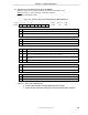
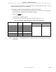
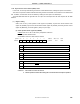
(a) Serial operation mode register 20 (CSIM20)
CSIM20 is set with a 1-bit or 8-bit memory manipulation instruction.
RESET input sets CSIM20 to 00H.
Set CSIM20 to 00H when UART mode is selected.
CSIE20
0
1
3-wire serial I/O mode operation control
First-bit specification
CSIE20
0
000
DIR20
CSCK20
0CSIM20
Symbol Address After reset R/W
FF72H 00H R/W
<7>6543210
Operation disabled
Operation enabled
CSCK20
0
1
3-wire serial I/O mode clock selection
External clock input to the SCK20 pin
Output of the dedicated baud rate generator
DIR20
0
1
MSB
LSB
Cautions 1. Bits 0 and 3 to 6 must be set to 0.
2. Switch operation modes after halting the serial transmission/reception operation.