
Electronics America Single-Chip Microcontrollers User's Manual

CHAPTER 11 SERIAL INTERFACE 20
User’s Manual U15331EJ4V1UD 201
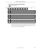
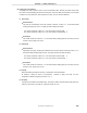
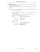
(c) Asynchronous serial interface status register 20 (ASIS20)
ASIS20 is set with a 1-bit or 8-bit memory manipulation instruction.
RESET input sets ASIS20 to 00H.
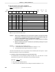
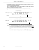
PE20
0
1
Parity error flag
No parity error occurred
A parity error occurred (when the transmit parity and receive parity did not match)
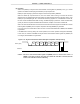
No framing error occurred
A framing error occurred (when stop bit was not detected)
Note 1
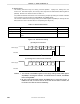
No overrun error occurred
An overrun error occurred
Note 2
(when the next receive operation was completed before data was read from reception buffer register 20)
FE20
0
1
0
1
Framing error flag
Overrun error flag
OVE20
0 0 0 0 0 PE20 FE20 OVE20ASIS20
76 54Symbol Address After reset R/W
FF71H 00H R
3 <2> <1> <0>
Notes 1. Even when the stop bit length is set to 2 bits by setting bit 2 (SL20) of asynchronous serial
interface mode register 20 (ASIM20), the stop bit detection at reception is performed with 1 bit.
2. Be sure to read receive buffer register 20 (RXB20) when an overrun error occurs. If not, an
overrun error will occur every time data is received.