
Electronics America Single-Chip Microcontrollers User's Manual

CHAPTER 11 SERIAL INTERFACE 20
204 User’s Manual U15331EJ4V1UD
(2) Communication operation
(a) Data format
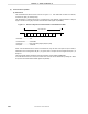
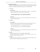
The transmit/receive data format is as shown in Figure 11-7. One data frame consists of a start bit,
character bits, parity bit, and stop bit(s).
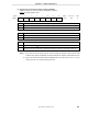
The specification of character bit length in one data frame, parity selection, and specification of stop bit
length is carried out using asynchronous serial interface mode register 20 (ASIM20).
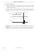
Figure 11-7. Format of Asynchronous Serial Interface Transmit/Receive Data
D0 D1 D2 D3 D4 D5 D6 D7
Parity
bit
Stop bit
Start
bit
One data frame
• Start bits ................... 1 bit
• Character bits............ 7 bits/8 bits
• Parity bits .................. Even parity/odd parity/0 parity/no parity
• Stop bits.................... 1 bit/2 bits
When 7 bits are selected as the number of character bits, only the lower 7 bits (bits 0 to 6) are valid; in
transmission the most significant bit (bit 7) is ignored, and in reception the most significant bit (bit 7) is
always “0”.
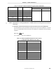
The serial transfer rate is selected by baud rate generator control register 20 (BRGC20).
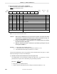
If a serial data receive error occurs, the receive error contents can be determined by reading the status
of asynchronous serial interface status register 20 (ASIS20).