
Electronics America Single-Chip Microcontrollers User's Manual

CHAPTER 12 SERIAL INTERFACE 1A0
User’s Manual U15331EJ4V1UD 221
(2) Automatic data transmit/receive control register 0 (ADTC0)
This register sets automatic reception enable/disable, the operation mode, and displays the state of
automatic transmit/receive control.
ADTC0 is set via a 1-bit or 8-bit memory manipulation instruction.
RESET input sets this register to 00H.
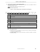
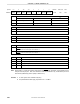
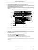
Figure 12-3. Format of Automatic Data Transmit/Receive Control Register 0
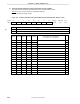
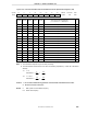
Symbol <7> <6> 5 4 <3> 2 1 0 Address After reset R/W
ADTC0 RE0 ARLD0 0 0 TRF0 0 0 0 FF79H 00H R/W
Note 1
RE0 Control of reception of automatic transmit/receive function
0 Reception disabled
Note 2
1 Reception enabled
ARLD0 Selection of operation mode for automatic transmit/receive function
0 One-shot mode
1 Repeat mode
TRF0 Status of automatic transmission/reception function
Note 3
0 Detection of termination of automatic transmission/reception (this bit is set to 0 upon suspension of automatic
transmission/reception or when ARLD0 = 0)
1 Automatic transmission/reception in progress (this bit is set to 1 when data is written to SIO1A0)
Notes 1. Bit 3 (TRF0) is read-only.
2. When RE0 is reset to 0, P25 (CMOS I/O) is used even when bit 7 (CSIE10) of serial operation
mode register 1A0 (CSIM1A0) is set to 1.
3. Use TRF0, instead of CSIIF10 (interrupt request flag), to identify the completion of automatic
transmission/reception.