
Electronics America Single-Chip Microcontrollers User's Manual

250 User’s Manual U15331EJ4V1UD
CHAPTER 13 LCD CONTROLLER/DRIVER
13.1 LCD Controller/Driver Functions
The functions of the LCD controller/driver of the
µ
PD789489 Subseries are as follows.
(1) Automatic output of segment and common signals based on automatic display data memory read
(2) Two different display modes:
• 1/3 duty (1/3 bias)
• 1/4 duty (1/3 bias)
(3) Four different frame frequencies, selectable in each display mode
(4) 16 to 28 segment signal outputs (S0 to S15, S16 to S27
Note
)
4 common signal outputs (COM0 to COM3)
Note Usable mask option or port function register
(5) Operation with subsystem clock is possible
(6) On-chip voltage booster
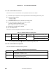
The maximum number of displayable pixels is shown in Table 13-1 below.
Table 13-1. Maximum Number of Display Pixels
Bias Method Time Division Common Signals
Used
Maximum Number
of Segments
Maximum Number of Display Pixels
3 COM0 to COM2 84 (28 segments × 3 commons)
Note 1
1/3
4 COM0 to COM3
28
112 (28 segments × 4 commons)
Note 2
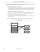
Notes 1. The LCD panel of the figure consists of 9 rows with 3 segments per row.
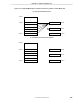
2. The LCD panel of the figure
consists of 14 rows with 2 segments per row.
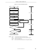
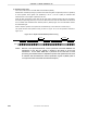
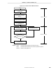
13.2 LCD Controller/Driver Configuration
The LCD controller/driver includes the following hardware.
Table 13-2. Configuration of LCD Controller/Driver
Item Configuration
Display outputs Segment signals: 16 to 28
Common signals: 4 (COM0 to COM3)
Control registers LCD display mode register 0 (LCDM0)
LCD clock control register 0 (LCDC0)
LCD voltage boost control register 0 (LCDVA0)