
Electronics America Single-Chip Microcontrollers User's Manual

CHAPTER 15 REMOTE CONTROLLER RECEIVER (
µ
PD789489, 78F9489 ONLY)
User’s Manual U15331EJ4V1UD
283
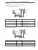
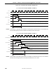
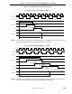
(4) End width determination
RIN
RMDLS
RMDLL
<1>
<2>
RIN
RMER
∆
Relationship Between RMER/Counter Position of Waveform Corresponding Operation
Counter < RMER <1>: Short Error interrupt INTRERR is generated.
Measuring the guide pulse high-level width is started.
RMER ≤ counter <2>: Long INTREND is generated at the ∆ point.
Reception via circuit stops until RMSR is read.
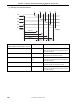
15.4.4 Compare register setting
This remote controller receiver has the following 9 types of compare registers.
• Remote controller receive GPHS compare register (RMGPHS)
• Remote controller receive GPHL compare register (RMGPHL)
• Remote controller receive DLS compare register (RMDLS)
• Remote controller receive DLL compare register (RMDLL)
• Remote controller receive DH0S compare register (RMDH0S)
• Remote controller receive DH0L compare register (RMDH0L)
• Remote controller receive DH1S compare register (RMDH1S)
• Remote controller receive DH1L compare register (RMDH1L)
• Remote controller receive end width select register (RMER)
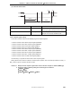
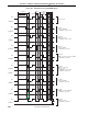
Use formulas (1) to (3) below to set the value of each compare register.
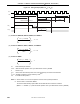
Making allowances for tolerance enables a normal reception operation, even if the RIN input waveform is RIN_1 or
RIN_2 shown in Figure 15-6 due to the effect of noise.
Cautions 1. Always set each compare register while remote controller reception is disabled (RMEN = 0).
2. Set the set values so that they satisfy all the following three conditions.
• RMGPHS < RMGPHL
• RMDLS < RMDLL
• RMDH0S < RMDH0L ≤ RMDH1S < RMDH1L