
Electronics America Single-Chip Microcontrollers User's Manual

CHAPTER 16 INTERRUPT FUNCTIONS
296 User’s Manual U15331EJ4V1UD
(2) Interrupt mask flag registers (MK0 to MK2)
Interrupt mask flags are used to enable and disable the corresponding maskable interrupts.
MK0 to MK2 are set with a 1-bit or 8-bit memory manipulation instruction.
RESET input sets these registers to FFH.
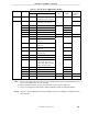
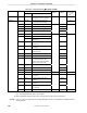
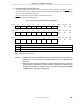
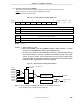
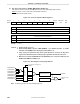
Figure 16-3. Format of Interrupt Mask Flag Registers
Symbol <7> <6> <5> <4> <3> <2> <1> <0> Address After reset R/W
MK0 CSIMK10 SRMK20 RINMK
Note
PMK3 PMK2 PMK1 PMK0 WDTMK FFE4H FFH R/W
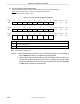
Symbol <7> <6> <5> <4> <3> <2> <1> <0> Address After reset R/W
MK1 WTMK ADMK0 TMMK61 TMMK60 TMMK50 TMMK20 WTIMK STMK20 FFE5H FFH R/W
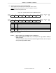
Symbol 7 6 <5> <4> <3> <2> <1> <0> Address After reset R/W
MK2 1 1
KRMK01
Note
DFULLMK
Not
e
RENDMK
Not
e
GPMK
Note
RERRMK
Not
e
KRMK00 FFE6H FFH R/W
××MK× Interrupt servicing control
0 Interrupt servicing enabled
1 Interrupt servicing disabled
Note
µ
PD789489 and 78F9489 only
Cautions 1. When the watchdog timer is being used in watchdog timer mode 1 or 2, any attempt to
read the WDTMK flag results in an undefined value being detected.
2. Because P30 to P33 function alternately as external interrupts, when the output level
changes after the output mode of the port function is specified, the interrupt request
flag will be inadvertently set. Therefore, be sure to preset the interrupt mask flag (PMK0
to PMK3) before using the port in output mode.