
Electronics America Single-Chip Microcontrollers User's Manual


CHAPTER 17 STANDBY FUNCTION
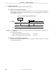
User’s Manual U15331EJ4V1UD 309
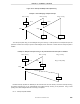
17.2 Standby Function Operation
17.2.1 HALT mode
(1) HALT mode
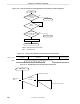
The HALT mode is set by executing the HALT instruction.
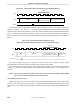
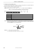
The operation statuses in the HALT mode are shown in the following table.
Table 17-1. Operation Statuses in HALT Mode
HALT Mode Operation Status During Main
System Clock Operation
HALT Mode Operation Status During Subsystem
Clock Operation
Item
Subsystem Clock
Operating
Subsystem Clock
Stopped
Main System Clock
Operating
Main System Clock
Stopped
Clock generator Oscillation enabled for both main system clock and subsystem clock, but clock supply to CPU is
stopped
Subsystem clock ×4
multiplication circuit
Operation stopped
CPU Operation stopped
Ports (output latches) Status before HALT mode setting retained
16-bit timer 20 Operable Operable
Note 1
8-bit timer 50 Operable Operable
Note 2
8-bit timer 60 Operable Operable
Note 3
8-bit timer 61 Operable Operable
Note 3
Watch timer Operable Operable
Note 4
Operable Operable
Note 5
Watchdog timer Operable Operation stopped
Key return circuit Operable
Serial interface 20 Operable Operable
Note 6
Serial interface 1A0 Operable Operable
Note 6
LCD controller/driver Operable
Note 7
Operable
Notes 4, 7
Operable
Note 7
Operable
Notes 5, 7
A/D converter Operation stopped
Multiplier Operation stopped
Remote controller
receiver
Note 8
Operable Operable
Note 4
Operable Operable
Note 5
External interrupts Operable
Note 9
Notes 1. Operation is enabled when the 24-bit counter mode is selected.
2. Operation is enabled when either the subsystem clock or the input signal from timer 60 (when timer 60
is operable) is selected as the count clock.
3. Operation is enabled only when the external input clock is selected as the count clock.
4. Operation is enabled when the main system clock is selected.
5. Operation is enabled when the subsystem clock is selected.
6. Operation is enabled only when an external clock is selected.
7. The HALT instruction can be set after display instruction execution.
8.
µ
PD789489 and 78F9489 only.
9. Operation is enabled only for a maskable interrupt that is not masked.