
Electronics America Single-Chip Microcontrollers User's Manual


CHAPTER 19 FLASH MEMORY VERSION
User’s Manual U15331EJ4V1UD 323
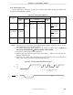
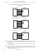
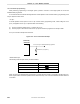
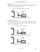
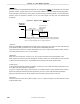
If Flashpro III/Flashpro IV is used as a dedicated flash programmer, the following signals are generated for the
µ
PD78F9488 and 78F9489. For details, refer to the manual of Flashpro III/Flashpro IV.
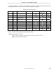
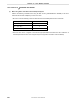
Table 19-3. Pin Connection List
Signal Name I/O Pin Function Pin Name 3-Wire Serial I/O 3-Wire Serial I/O
with Handshake
UART
VPP1 Output Write voltage VPP
VPP2
− − −
× × ×
VDD I/O VDD voltage generation/
voltage monitoring
VDD
Note Note Note
GND
−
Ground VSS
CLK Output Clock output X1
RESET Output Reset signal RESET
SI Input Receive signal SO20/TxD20
SO Output Transmit signal SI20/RxD20
SCK Output Transfer clock SCK20
×
HS Input Handshake signal P11 (HS)
×
×
Note V
DD voltage must be supplied before programming is started.
Remark : Pin must be connected.
: If the signal is supplied on the target board, pin does not need to be connected.
× : Pin does not need to be connected.