
Electronics America Single-Chip Microcontrollers User's Manual


CHAPTER 22 ELECTRICAL SPECIFICATIONS (
µ
PD789488, 78F9488, 789489, 78F9489)
User’s Manual U15331EJ4V1UD 347
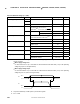
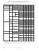
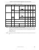
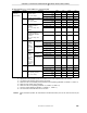
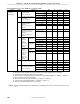
DC Characteristics (TA = –40 to +85°C, VDD = 1.8 to 5.5 V) (2/6)
Parameter Symbol Conditions MIN. TYP. MAX. Unit
ILIH1 P00 to P07, P10, P11,
P20 to P25, P30 to P34,
P60 to P67,
P70 to P73
Note 1
, P80 to
P87
Note 1
, RESET
3
µ
A
ILIH2
V
I = VDD
X1, X2, XT1, XT2 20
µ
A
Input leakage current,
high
I
LIH3 VI = 12 V P50 to P53
(N-ch open drain)
20
µ
A
ILIL1 P00 to P07, P10, P11,
P20 to P25, P30 to P34,
P60 to P67,
P70 to P73
Note 1
, P80 to
P87
Note 1
, RESET
–3
µ
A
ILIL2 X1, X2, XT1, XT2 –20
µ
A
Input leakage current,
low
I
LIL3
V
I = 0 V
P50 to P53
(N-ch open drain)
–3
Note 2
µ
A
Output leakage current,
high
ILOH VO = VDD 3
µ
A
Output leakage current,
low
ILOL VO = 0 V –3
µ
A
Software pull-up
resistor
R1 VI = 0 V P00 to P07, P10, P11,
P20 to P25, P30 to P34
50 100 200 kΩ
Mask option pull-up
resistor
Note 3
R
2 VI = 0 V P50 to P53 10 30 60 kΩ
Notes 1. Only when selected by a mask option or port function register
2. If there is no on-chip pull-up resistor for P50 to P53 (specified by a mask option) and if P50 to P53
have been set to input mode when a read instruction is executed to read from P50 to P53, a low-level
input leakage current of up to –60
µ
A flows during only one cycle. At all other times, the maximum
leakage current is –3
µ
A.
3. Mask ROM version only
Remark Unless otherwise specified, the characteristics of alternate-function pins are the same as those of port
pins.