
Electronics America Single-Chip Microcontrollers User's Manual

CHAPTER 4 PORT FUNCTIONS
User’s Manual U15331EJ4V1UD 79
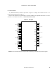
4.2.3 Port 2
This is a 6-bit I/O port with an output latch. Port 2 can be specified in the input or output mode in 1-bit units by
using port mode register 2 (PM2). When using the P20 to P25 pins as input port pins, on-chip pull-up resistors can be
connected in 1-bit units by using pull-up resistor option register B2 (PUB2).
This port is also used for serial interface I/O.
RESET input sets this port to input mode.
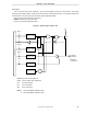
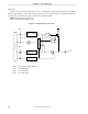
Figures 4-4 to 4-8 show block diagrams of port 2.
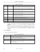
Caution When using the pins of port 2 as the serial interface, the I/O or output latch must be set
according to the function to be used. For how to set the latches, see Table 11-2 Serial Interface
20 Operation Mode Settings and 12.3 (1) Serial operation mode register 1A0 (CSIM1A0).
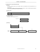
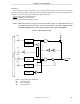
Figure 4-4. Block Diagram of P20
Internal bus
V
DD
P-ch
P20/ASCK20/
SCK20
WR
PUB2
RD
WR
PORT
WR
PM
PUB20
Alternate
function
Output latch
(P20)
PM20
Alternate
function
Selector
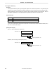
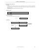
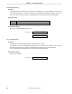
PUB2: Pull-up resistor option register B2
PM: Port mode register
RD: Port 2 read signal
WR: Port 2 write signal