Multimedia Monitor User's Manual R 37 Xtra 37 Xtra R R 37 Xtra 37 Xtra NEC Technologies, Inc. 1250 N. Arlington Heights Road, Suite 500 Itasca, Illinois 60143-1248 MultiSync is a registered trademark of NEC Technologies, Inc. in the U.S.A. NEC is registered trademark of NEC Corporation. 1993 by NEC Technologies, Inc.
CAUTION RISK OF ELECTRIC SHOCK DO NOT OPEN CAUTION: TO REDUCE THE RISK OF ELECTRIC SHOCK, DO NOT REMOVE COVER. NO USER-SERVICEABLE PARTS INSIDE. REFER SERVICING TO QUALIFIED SERVICE PERSONNEL. This symbol warns the user that uninsulated voltage within the unit may have sufficient magnitude to cause electric shock. Therefore, it is dangerous to make any kind of contact with any part inside of this unit.
ATTENTION RISQUE D’ELECTROCUTION NE PAS OUVRIR MISE EN GARDE: AFIN DE REDUIRE LES RISQUES D’ELECTROCUTION, NE PAS DEPOSER LE COUVERCLE, IL N’Y A AUCUNE PIECE UTILISABLE A L’INTERIEUR DE CET APPAREIL. NE CONFIER LES TRAVAUX D’ENTRETIEN QU’A UN PERSONNEL QUALIFIE. Ce symbole a pour but de prévenir l’utilisateur de la présence d’une tension dangereuse, non isolée se trouvant à l’intérieur de l’appareil. Elle est d’une intensité suffisante pour constituer un risque d’électrocution.
LIMITED WARRANTY NEC Multimedia Monitor Products NEC Technologies, Inc.(hereafter NECTECH)warrants this product to be free from defects in material and workmanship under the following terms. HOW LONG IS THE WARRANTY Parts and labor are warranted for (1) One Year and CRT’s for (1) One year from the date of the first customer purchase. WHO IS PROTECTED This warranty may be enforced only by the first purchaser.
CONTENTS 1. Introduction Introduction to the MultiSync XP37 Xtra/XM37 Xtra .............................................................. 1 Feature Highlights ...................................................................................................................... 1 2. Part Names and Functions Front View / Rear View ............................................................................................................. 3 Terminal Board .....................................................
1 OSM and IPM are trademarks of NEC Technologies, Inc. IBM PC/AT, PS/2, VGA, S-VGA, 8514/A and XGA are registered trademarks of International Business Machines Corporation. Apple and Macintosh are registered trademarks of Apple Computer, Inc. Microsoft is a registered trademark of Microsoft Corporation. Windows is a trademark of Microsoft Corporation.
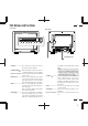
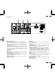
3 Part Names and Functions Front View Rear View EXIT VIDEO 1 ▼ VIDEO 2 RGB 1 RGB 2/DTV ▼ PROCEED − + POWER ON OFF DEGAUSS VIDEO 1 VIDEO 2 RGB 1 POSITION / CONTROL RGB 2 PROCEED EXIT POWER /STANDBY SCAN WIDTH HEIGHT SIDE PIN NORMAL NORMAL BRIGHT CONTRAST MUTE VOLUME MULTIMEDIA MONITOR RD-346E 79644641 9 8 7 6 5 4 3 21 VIDEO 1 VIDEO 2 RGB AUDIO RGB 1 SPEAKER SELECT INT IN BNC BNC S IN IN THROUGH OUT THROUGH OUT R S RIGHT SPEAKRES MUST HAVE MORE THAN 5WATT RATING INPEDANC
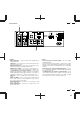
5 Terminal Board C VIDEO 1 VIDEO 2 RGB AUDIO RGB 1 SPEAKER SELECT INT IN BNC BNC S R S IN RIGHT THROUGH OUT THROUGH OUT THROUGH OUT LEFT HIGH OUT 75Ω DIP SW ON RGB 2 R/CR/PR HIGH 75Ω HIGH AUDIO R 75Ω AUDIO L (MONO ) R IN IN THROUGH OUT THROUGH OUT G/Y/Y B/CB/PB PC/EXT CTL IN SPEAKRES MUST HAVE MORE THAN 5WATT RATING INPEDANCE 8 OHM THROUGH OUT A REMOTE EXT EXT SPEAKER L (MONO ) IN IN B H/CS V 12345678 IN AC IN L (MONO ) THROUGH OUT HIGH 75Ω HIGH 75Ω D
7 Terminal Board H VIDEO 1 F G VIDEO 2 RGB AUDIO RGB 1 SPEAKER SELECT INT IN BNC S BNC R S EXT SPEAKER L (MONO ) RIGHT IN IN IN THROUGH OUT THROUGH OUT SPEAKRES MUST HAVE MORE THAN 5WATT RATING INPEDANCE 8 OHM THROUGH OUT THROUGH OUT HIGH HIGH 75Ω HIGH AUDIO R 75Ω AUDIO L (MONO ) R IN IN THROUGH OUT THROUGH OUT G/Y/Y B/CB/PB REMOTE PC/EXT CTL IN LEFT OUT 75Ω DIP SW ON RGB 2 R/CR/PR EXT H/CS V IN 12345678 AC IN L (MONO ) THROUGH OUT HIGH 75Ω F RGB 1 (Mini
9 Terminal Board I VIDEO 1 VIDEO 2 RGB AUDIO RGB 1 SPEAKER SELECT INT IN BNC BNC S THROUGH OUT R S EXT SPEAKER L (MONO ) RIGHT IN IN IN SPEAKRES MUST HAVE MORE THAN 5WATT RATING INPEDANCE 8 OHM THROUGH OUT THROUGH OUT THROUGH OUT HIGH HIGH 75Ω HIGH AUDIO R 75Ω AUDIO L (MONO ) R IN IN THROUGH OUT THROUGH OUT G/Y/Y B/CB/PB REMOTE PC/EXT CTL IN LEFT OUT 75Ω DIP SW ON RGB 2 R/CR/PR EXT H/CS V IN 12345678 AC IN L (MONO ) THROUGH OUT HIGH 75Ω HIGH 75Ω J I VID
Remote Control Unit NOTE: When not in use the remote control unit is conveniently stowed in the holder on the rear panel. 1 POWER ON/OFF Press POWER ON to turn the monitor on when the POWER/STANDBY indicator is lit amber. Press POWER OFF to turn the monitor off and the monitor will go into the standby condition. 2 POWER ON OFF DEGAUSS VIDEO 1 VIDEO 2 RGB 1 POSITION / CONTROL Press to demagnetize the picture tube in the manual operation. See also RGB 2 PROCEED EXIT 4 1 2 DEGAUSS 3 5 page 27.
13 Raster Control 7 WIDTH ( + / -) Adjusts the horizontal size of the image. 8 HEIGHT ( + / -) Adjusts the vertical size of the image. 9 SIDE PIN ( + / -) Adjusts the curvature of the edges of the left and right side of the display POWER ON OFF DEGAUSS image either inward or outward. The image should be adjusted to attain a VIDEO 1 VIDEO 2 RGB 1 POSITION / CONTROL RGB 2 straight line on the left and right sides.
15 Battery Installation and Replacement The remote control is powered by two 1.5V AA batteries. 1. Turn the remote control unit upside down. Press down on the battery compartment grip and slide the compartment in the direction of the arrow. 2. Install the two new batteries, making sure that their polarity matches the (+) (-) diagrams inside the battery compartment. Incorrect polarity could damage the remote control unit. 3. Close the battery compartment cover.
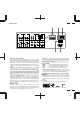
17 Functions of DIP SW ON ON 1 2 3 4 5 6 7 8 OFF Functions and Settings of DIP SW This DIP switch is used for Sync. Control, Intelligent Power Manager, External control, wireless control, and OSM control. To change a switch setting use a pointed object, such as a pen or pencil, to push the switch to the desired position. Set all the pins except No.7 to the OFF position during normal operation. The pins nos 2,3 and 5 are not used. Pin No 1 (Sync. Control ) The No. 1 pins set Sync. Control.
19 Installation Macintosh or Compatibles Wiring Diagram IBM XGA/SuperVGA/VGA or Compatibles or Macintosh G3 series EXTERNAL CONTROL RGB cable (Supplied) To Mini D-SUB 15 Pin input To EXTERNAL CONTROL (Mini D-SUB 15 Pin input) Pin adapter for Macintosh (supplied) RGB cable (Supplied) To Mini D-SUB 15 Pin input XP37 Xtra/XM37 Xtra VIDEO 1 VIDEO 2 RGB AUDIO RGB 1 SPEAKER SELECT INT IN BNC S BNC R S RIGHT IN IN IN THROUGH OUT THROUGH OUT EXT EXT SPEAKER L (MONO ) SPEAKERS MUST HAVE MOR
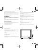
21 Connecting Your PC or Macintosh Computer Connecting your PC or Macintosh computer to your MultiSync XP37 Xtra/ XM37 Xtra will enable you to display your computer's screen image.
23 Daisy-chaining Your monitors The REMOTE IN/OUT terminals allow you to control monitors by one remote control. NOTE: The connection of three XP37 Xtra/XM37 Xtra monitors or more with THROUGH OUT (VIDEO 1 or 2) terminals may degrade image quality. To do so: When using the VIDEO inputs: THROUGH OUT (VIDEO 1) Connections 1. Connect THROUGH OUT 1 BNC or S-VIDEO 1 OUT to external components to relay the signal input at VIDEO 1 IN(BNC-type), or S-VIDEO 1 IN. 2.
25 External Speaker Connections External speakers may be connected to the monitor to reproduce sound from VIDEO 1, VIDEO 2, RGB 1 or RGB 2 signal sources. External speakers may be connected directly to the EXTERNAL SPEAKERS terminals or indirectly by connecting a stereo system amplifier to the audio outputs. If non-shielded speakers are used, they must be located a minimum of 4 feet away from the monitor.
27 Operation Power This section describes how to select a computer or video source and how to adjust the picture and sound. General Controls Before you turn on your MultiSync XP37 Xtra/XM37 Xtra monitor ensure that the computer or video source is turned on. 1)To adjust: 1. Turn On The Monitor The power button is on the front panel of the monitor. By turning this switch on, the STANDBY/POWER indicator will turn to green and the monitor will become ready to use. OSM is also usable from the rear panel.
29 Direct Control Screen You can adjust the raster, visual and sound using the direct key on the remote control. To switch to another control screen, press any one of the other keys. *To end the OSM display, press EXIT. *If no key operation is made within 3 seconds, the OSM display will disappear. a. POSITION/CONTROL Press to move the image right. Press Press to move the image up. Press c. HEIGHT Press to adjust the vertical size of the image. d.
31 i. NORMAL( visual) Press to reset all the stored adjustment visual data and recall the factory preset data. When a specific control is selected, this key resets the selected visual adjustments. j. MUTE Press to turn off the sound for a short period of time; press again to restore the sound. k. VOLUME Press to increase the sound: press to decrease the sound. NOTE: When pressing a key that does not correspond to the function currently in use, the following message will be displayed on the monitor.
33 H-position/H-width/Pin-cushion Controls Group V-position/V-height/V-linearity Controls Group The H-position/H-width/Pin-cushion Controls allow you to adjust the horizontal position, horizontal size and pin-cushion of the image. The V-position/V-height/V-linearity Controls allow you to adjust the vertical position, vertical size and vertical linearity of the image.
35 RGB Controls Group OSM Location/OSM Display Time Control The RGB Controls allow you to adjust the color temperature and the white balance for RGB input. You can choose where you would like OSM image to appear on your screen. Selecting OSM location allows you to manually adjust the OSM menu left, right, up, or down. The OSM menu will stay on as long as it is in use. In the OSM Turn Off Time submenu, you can select how long the monitor waits after the last touch of a key to shut off the OSM menu.
37 If the monitor does not reproduce the color for a component signal correctly, the monitor will select YCBCR/YPBPR in accordance with an output format of the connected equipment such as DVD player or DTV tuner. Selecting RGB CTL allows you to adjust the Color, Tint, Sharpness, Gamma, Dynamic Picture control for RGB signals -provided horizontal frequencies of these RGB signals must be 60 kHz and below. This mode is recommended for displaying movie or graphics.
39 Specific Item Settings OSM System Control Menu The OSM System control menu allows you to set a various conditions of the monitor. Specific adjustment item to be reset. NOTE: This control is available only when No. 8 pin of the DIP switch is set at the ON position. The DIP switch is located on the back cabinet. The above warning statement will appear to confirm that you do want to reset individual settings.
41 LANGUAGE OSM menus are available in six languages: English, German, French, Spanish, Italian, and Swedish. VIDEO MODE This control allows you to select the NTSC, PAL, or SECAM video standard. Normally select AUTO. OSM ON/OFF This control allows you to enable the OSM control. The OSM control is available when ON is selected. When the OSM does not appear, the visual and raster controls are available with the remote control. PC-CONTROL This control allows you to activate the PC-control function.
43 Command reference Control Data Format You can control the main functions from external equipment such as personal computer using the PC/EXT CTL terminals. The following sections explain the interface. Interface Condition • RS-232C • Baud rate ------------------------- 9600 bps • Data length ----------------------- 8 bits • Parity ------------------------------- Odd parity 8bit 8bit 8bit 8bit 8bit 8bit Data Data length Command 2 UNIT ID Command 1 8bit Check Sum Command 1 ........
45 Troubleshooting Before arranging for service by the NEC Service Center, check the following to be sure repairs are needed. Possible Cause Problem Correction Power cord unplugged. Power outlet inactive. Plug in power cord. Be sure wall switch is on and outlet has power. Power of external equipment is not ON. Switch to ON or connect to an active AC outlet. External equipment has been incorrectly connected. Incorrect input selection. Correct all connections.
47 Specifications Picture tube 36 inch Visual size; 37 inch CRT size (Diagonal), Type M90AHL50X 108 degree deflection Stripe trio pitch Ph 0.90 mm at center, Ph 1.10 mm at corner/Pv 0.7 mm Invar mask, Medium-short persistence phosphor Dynamic focus RGB Input Terminals RGB 1 : : : : : Mini D-SUB 15pin RGB 2: (R/C R/PR /,G/Y/Y,B/CB/P B, H/CS and V) Video : Analog 0.7Vp-p/75 Ohms (Positive) Sync. : Separate Sync. TTL level, 0.7 - 4.0Vp-p/75 Ohms..........RGB 2 only Horizontal Sync.
49 Maximum Resolution RGB 1024( H) X 768(V) pixels VIDEO Horizontal: 500 lines /S-VIDEO Horizontal : 600 lines Video Bandwidth RGB: 70 MHz at-3dB YPBPR, YC BCR and RGB CTL : 25MHz at-3dB VIDEO: 6 MHz at-3dB Display Area RGB : 95% Scan (Typically) VIDEO: 7% Overscan Blanking Horizontal: 15.75kHz: 7.0µsec, 30kHz
51 Dimensions 24.
53 Timing Charts Input Signal Reference Chart Separate Sync. VIDEO D C HORIZONTAL E B A VIDEO VERTICAL Q R S P Sync. Polarity: Positive / Negative O Composite Sync. VIDEO HORIZONTAL D C E B A VIDEO Q VERTICAL R S P O Sync.
55 Composite Sync. & Video (Sync. on Green) VIDEO HORIZONTAL B E D C A VIDEO VERTICAL P P R Q S O Sync. Polarity: Negative Recommended Sync Signal Timing Horizontal sync duty should be 3 to 30%. Horizontal sync width should exceed 0.9 µsec. Horizontal back porch should exceed 2.0 µsec at sync on green and 1.2 µsec at others except when at 15KHz. Horizontal blanking should exceed: 7.0µse at fH 15.75kHz, 3.3µsec at 30 kHz
57 Typical Input Signal Timing VGA Compatible Resolution Mac Ⅱ, Quadra, or LC Compatible XGA-2 Compatible 640×350 720×400 640×480 720×350 720×400 640×480 640×480 Horizontal Frequency 31.469KHz 31.469KHz 31.469KHz 39.444KHz 39.444KHz 39.375KHz 35.000KHz (A) Horizontal Period 31.778µsec 31.778µsec 31.778µsec 25.352µsec 25.352µsec 25.397µsec 28.570µsec (B) Horizontal Pulse Width 3.813µsec 3.813µsec 3.813µsec 3.042µsec 3.042µsec 3.048µsec 2.
59 VGA Compatible Resolution 640×350 Mac Ⅱ, Quadra, or LC Compatible XGA-2 Compatible 720×400 640×480 720×350 720×400 640×480 640×480 Vertical Frequency 70.080Hz 70.080Hz 59.940Hz 87.850Hz 87.850Hz 75.000Hz 66.667Hz (O) Vertical Period 14.268msec 14.268msec 16.683msec 11.383msec 11.383msec 13.333msec 15.000msec (P) Vertical Pulse Width 0.064msec 0.064msec 0.064msec 0.051msec 0.051msec 0.051msec 0.090msec (Q) Vertical Back Porch 1.716msec 0.890msec 0.793msec 1.
61 Signal Identification for Raster Preset MODE MODE1 15.5-21.0KHz MODE2 31.0-33.0KHz MODE3 33.0-37.0KHz MODE4 37.0-43.0KHz MODE5 43.0-49.0KHz MODE6 49.0-54.0KHz MODE7 54.0-58.0KHz MODE8 58.0-64.0KHz MODE9 64.0-74.0KHz MODE10 74.0-85.0KHz MODE11 85.0-100.
63 Service and Support Policies NEC Technologies is committed to providing the highest quality service and support for your MultiSync presentation monitor. A customer service group that is dedicated to the support of this product line is available to provide a single point of contact for technical support, trouble shooting, service and repair issues.
DECLARATION OF CONFORMITY This device complies with Part 15 of FCC Rules. Operation is subject to the following two conditions. (1) This device may not cause harmful interference, and (2) this device must accept any interference received, including interference that may cause undesired operation. U.S. Responsible Party: Address: Tel. No.: NEC Technologies, Inc. 1250 North.