User’s Manual IP Telephony Gateway Model No.: SP5008A, SP5018A, SP5058A Website: http://www.micronet.
About this User’s Manual This User’s Manual gives users basic steps on installation and operation. Please read this manual chapter by chapter. Chapter 1. Introduction Introduce the IP Telephony Gateway to users in terms of feature, appearance, and application. Chapter 2. Startup Help user complete basic configuration. Chapter 4. Web Administration Provide command reference of Web Interface for advanced setting. Chapter 3. Operation Show user how to use the device to process phone call. Chapter 6.
Table of Content 1. ..Introduction.............................................................................................. 4 1.1 Key Features ................................................................................................ 4 1.2 Physical Description ..................................................................................... 5 2. ..Startup ...................................................................................................... 7 2.1 Login into the System ...
3.4 3.3.4 Reset to Default............................................................................................. 58 3.3.5 Network Status .............................................................................................. 59 3.3.6 Version Info. .................................................................................................. 60 3.3.7 Port Status..................................................................................................... 61 3.3.8 Password..
1. Introduction Micronet SP5008A / SP5018A / SP5058A are high-capacity SIP Gateway Series that provides 8 FXS / 4 FXS + 4 FXO / 8 FXO ports, and suit to build an IP-based communication platform with other VoIP devices. They meet enterprise’s requirement for functionality (VoIP) upgrade and larger scale implementation by interoperating with legacy PABX and IP PBX/Soft-switch. To connect with legacy PABX, SP5018A supports PABX Mode for PSTN backup.
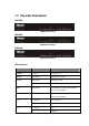
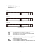
1.2 Physical Description SP5008A: SP5008A Front Panel SP5058A SP5058A Front Panel SP5018A SP5018A Front Panel LED Indicators LED Status Description POWER On / Green The Power is on READY Blink / Green Booting up for self test PROXY Blink / Green Gateway reg. fails Constant / Green Gateway reg.
1*. SP5008A: FXS = T1 - T8 SP5018A: FXS = T1 - T4, FXO = L1 - L4 SP5058A: FXO = L1 - L8 SP5008A SP5008A Rear Panel SP5058A SP5058A Rear Panel SP5018A SP5018A Rear Panel --------------------------------------------------------------------------------------------------RESET Factory default button. Press and hold for 5 seconds to reset T1-T8 The RJ-11 FXS port 1-8, connects analog phone sets, trunk line in PABX.
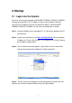
2. Startup 2.1 Login into the System First of all, connect your computer to MICRONET SP5008A / SP5018A / SP5058A’s LAN port by using DHCP. The IP address assign to your computer should be 192.168.123.x by default. Once you can get the IP address from MICRONET SP5008A / SP5018A / SP5058A, you can start the configuration as below. Step 1. Connect LAN port to your managing PC. Or, connect the gateway with PC by hub/switch. Step 2. Launch your web browser with http://192.168.123.123/.
8
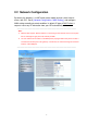
2.2 Network Configuration By default, the gateway is in NAT mode (router mode) and can share Internet access with PCs. Go to [ Network Configuration / WAN Setting ], and configure WAN setting according to actual condition. In default IP type of DHCP client, it requests necessary IP information from your ISP automatically. ----------------------------------------------------------------------------------------------------Note: 1. Different ISPs require different methods of connecting to the Internet.
WAN Setting Item Description Connected mode Select the connection method for Static IP DHCP PPPoE V V V V V V V V V V V V V V V V V V V V V the WAN port of the SP5008A/SP5018A/SP5058A, you can choose the following: z Static IP z DHCP z PPPoE Current IP Address Show current IP address DNS server mode Select the DNS behavior, you can choose the following: z Auto z Manual “DNS auto” will retrieve the DNS information sent from the DHCP server.
Item Description Static IP Default gateway Specify the IP address of the default gateway. Remote access Restricts/Blocks users connecting to restriction the WAN port’s IP remotely, you can DHCP PPPoE V V V V Enable/Disable this option. PPPoE userID Specify the username of the PPPoE account PPPoE password Specify the password associated to the PPPoE account above.
2. Press the “Reboot” button to apply the changes. 2.2.2 DHCP 1. 2. Press the “Apply” button (at the bottom) after you finish to save changes. Press the “Reboot” button to apply the changes. ----------------------------------------------------------------------------------------------------Note: When you are using DHCP in WAN and not connected, please make sure you connect Ethernet before use PC to connect to LAN port.
2.2.3 PPPoE 1. Input PPPoE user ID and password 2. Press the “Apply” button (at the bottom) after you finish to save changes. 3. Press the “CANCEL” button (next to the Apply button) to clear the values in the page. 4. Press the “Reboot” button to apply the changes.
2.2.4 LAN Setting ITEM Description LAN IP address Specify the IP address of the SP5008A / SP5018A / SP5058A LAN port. LAN mask address Specify the mask address for SP5008A / SP5018A / SP5058A LAN port. DHCP server Enable/Disable DHCP function on the LAN port. Once enabled, the LAN ports will function as a DHCP server, network devices connected to them will be issued with IP addresses.
ITEM Description Domain Name You can specify the domain name that will be assigned by the DHCP server to the attached network devices. The DHCP server will send information on the “server host name” to the DHCP client. Lease time(sec) You can specify the maximum lease time of the IP address allocated to the DHCP client. DNS server mode Select the DNS behavior, you can choose the following: z Auto z Manual “DNS auto” will retrieve the DNS information sent from the DHCP server.
2.3 General configuration To make VoIP calls, you will need a SIP account provided by the SIP Proxy you are registered with. To configure the relevant SIP settings, please refer to the instructions explained below. 2.3.1 PABX Mode (SP5018A only) This quick setting is used for MICRONET SP5018A to operate in PABX connection mode between PSTN and traditional PABX. Enable PABX mode for ISP/ITSP scenario that forbids SIP call to/from PSTN via the gateway (SP5018A). The call scenario will be working as below: 1.
3.3.2.1 Primary FXS SIP settings When you have multiple SIP accounts for each FXS line, please set Representative Number Only to No. Then refer to 3.3.2.1 for the detail FXO Dialing Prefix When the prefix is set here, the call will be route to FXO instead of VOIP.
2.3.2 SIP Setting Primary proxy/P2P IP Specify the data of primary proxy : Enable/Disable, IP address, Port#, Domain Name, Expire time and MWI TTL. The P2P mode will be explained in paragraph Appendix A Secondary proxy Specify the data of secondary proxy: Enable/Disable, IP address, Port#, Domain Name, Expire time and MWI TTL. When you enable secondary proxy, it will start to register no matter whether primary proxy is registered or not.
Register or Unregister to SIP Proxy Account Input the SIP Proxy registration account ID. Number Input the phone number. Password Input the password of IP Proxy registration account ID. Display name Specify the Display name of the phone number Forward Specify the Representative forwarding type to be used, only choose busy Forward Number Specify the number to be forwarded when the specified forward condition is met. Ring Type Select the Ring Type of representative number.
3. Web Administration 3.1 General configuration 3.1.1 SIP Advanced Setting Local SIP port (1~65535) Specify the local SIP port’s number. Local RTP port (1~65535) Specify the local RTP port’s number. Session Expire (Sec) Specify the session expire time that will be used to negotiate with the remote host or proxy. Min Session Expire (Sec) Specify the minimum session expire time that other host or proxy will need to follow when calling the MICRONET SP5008A/SP5018A/SP5058A.
Session Refresh Request message. Unregister All Send SIP unregister signaling message after the SP5008A / SP5018A / SP5058A has been restarted Early media Treatment Use early media treatment SIP protocol, where SIP invite messages will not include SDP. Support SIP Ping Special feature used with only Nortel’s SIP proxy. IP Anonymous Caller ID When this feature is Enabled, all IP outgoing calls’ Caller ID will not be displayed to the destination.
3.1.2 Payload Type Setting RFC2833 payload type Specify the RFC2833 payload type (range is 96~128, however 100, 102~105 is reserved by other payload types). T.38 FAX payload type Specify the FAX payload type (range is 96~128, however 100, 102~105 is reserved by other payload types) T.38 Redundancy payload type Specify the Redundancy payload type (range is 96~128, default value is 104. 100, 102, 103, 105 is reserved by other payload types). T.
1. 2. Press the “Apply” button (at the bottom) after you finish to save changes. Press the “Reboot” button to apply the changes.
3.1.
If you enable the No Answer Forward No Answer Forward Time (FXS only) function (Representative number or L1~L8 number), please specify the time of no answer. The default setting is 30 sec. Enable/Disable FAX T.38 function. FAX Line1~Line8 relevant data Type Displays the port type of that particular line. Enable Enable the line or not Reg Register or Unregister to SIP Proxy Number Displays the line numbers that specified in SIP Setting. Account: Input the SIP Proxy registration account ID.
1. 2. Press the “Apply” button (at the bottom) after you finish to save changes. Press the “Reboot” button to apply the changes.
3.1.4 Qos Setting Select Qos Type: DSCP or ToS Type Differentiated Services Code Point Setting (DSCP) DSCP RTP Select the DSCP value for RTP (voice packets), the value in the drop down list is expressed in binary format, you can choose to meet your network environment. DSCP Signal Select the DSCP value for SIP message, the value in the drop down list is expressed in binary format, you can choose to meet your network environment.
3.1.
Peer to Peer call You can use speed dial to do the peer to peer call as follows: Speed Dial Editor Specify the speed Dial Number/Telephone (In P2P application) Number/Name, then press the Add or Del button to add or delete record The format of “Telephone Number” is “#@ip address: port”, for example 2000@192.168.23.
3.1.6 Caller ID Setting Caller ID Setting (Line 1~Line 8) Select the (Line 1~Line 8)Caller ID generation type to use, you can choose the following: z Disable z DTMF z FSK(Bellcore) z ETSI(Before Ring) z ETSI(Between ring) FXO only choose Enable/Disable the caller ID detection AUTO: You can choose different caller ID type by line. If Line1~Line 8 uses the same type, you only need to set line 1 and click the “Auto” button, then the other lines will set the same type automatically.
The default symbol is C. 1. 2. Press the “Apply” button (at the bottom) after you finish to save changes. Press the “Reboot” button to apply the changes.
3.1.7 CDR Setting Select the CDR mode for Enable or Disable. If CDR mode you Enable this feature, please specify the CDR Server address and port number at the CDR server address and port’s text box, then you can get Call Detail Data form CDR Server. If you Enable the CDR mode, please specify the CDR Server address IP address of CDR Sever for data storage. Specify the CDR Server port number, CDR Server port The default port number is 514. 1. 2.
33
3.1.8 Syslog Setting This syslog is used to send the debug log from MICRONET SP5008A / SP5018A / SP5058A to syslog server. Select the Syslog mode for Enable or Disable. If Syslog mode you Enable this feature, please specify the Syslog Server address and port number at the Syslog server address and port’s text box, then you can get detail system log from Syslog server. If you Enable the Syslog mode, please specify Syslog Server address the IP address of Syslog Sever for data storage.
35
3.2 Advanced Configuration 3.2.1 System setting prack PRACK is defined in RFC 3262: Reliability of Provisional Responses in SIP. You can accommodate your softswitch (Proxy Server) to Enable or Disable this feature. ROH (FXS only) Receiver-Off-Hook (ROH) Tone A ROH tone is sent to the subscriber to inform him that his receiver is off-hook. You can Enable/Disable this option. Send billing signal (FXS only) Polarity Reversal for billing signal, you can enable (Reverse)/Disable the feature. T.
z T.30 FAXByPass Codec Auto Select the FAX ByPass Codec to use, you can choose the following: Flash key function (FXS only) z G.711 a-law z G.711 u-law z G.
the announcement of IP address of LAN port, or press #126# to get WAN port IP address. FXO please following under step: 1. You can get a PSTN line and connect to the L1 FXO port. 2. Use another PSTN phone to dial the PSTN number (in step 1you connected on FXO-08), you will hear a second dial tone or greeting (please dial extension number). 3. Press #126# on the phone set, and you will hear an IVR announcing the current IP address of the WAN port. 4.
The default setting is “Disable”, if you are not using this particular special application mentioned above, please do not enable this function. ping ip to keep alive network Specify the IP for pinging to make sure the network keeps alive. ping timer(sec) 1. 2. Specify the interval of ping timer(sec) Press the “Apply” button (at the bottom) after you finish to save changes. Press the “Reboot” button to apply the changes.
3.2.2 SNTP Setting SNTP mode Select the SNTP mode : On or Off SNTP server address Specify the SNTP server address for time synchronization. Time Zone -GMT Select the Time Zone of your location Time setting You can specify the time with year/month/date /hour/minute /second when you select the SNTP mode with “Off”. 1. 2. Press the “Apply” button (at the bottom) after you finish to save changes. Press the “Reboot” button to apply the changes.
3.2.3 Codec Setting Codec Priority You can specify the priority of the codec from First to Fifth (first being the highest priority and Fifth being the lowest).
3.2.4 Voice Setting Jitter Buffer Minimal Delay Specify the minimal delay of the jitter buffer. The range is 0~150 ms and the default setting is 0 ms. Maximal Delay Specify the maximal delay of the jitter buffer. The range is 0~200 ms and the default setting is 200 ms. OPTFactor Specify the dynamic jitter buffer frame error/delay optimization factor, the range is 0~13. VAD Enable/Disable the VAD (Voice Activity Detection) feature. This is supported on all codecs that the FXS-FXO equips.
You can set this option for each of the 8 lines. 1. Press the “Apply” button (at the bottom) after you finish to save changes. 2. Press the “Reboot” button to apply the changes.
3.2.5 Tone Setting Dial tone Specify the pattern of the Dial tone, you can adjust the high frequency, low frequency, high level, low level, the On and Off time for tone 1 and 2. Ringback tone (FXS only) Specify the pattern of the Ringback tone, you can adjust the high frequency, low frequency, high level, low level, the On and Off time for tone 1 and 2.
NOTE: If the disconnect tone only has single frequency, please set it to low frequency. If the disconnect tone only has single cadence, please set it to Tone 1. Disconnect tone 2 Specify the pattern of the disconnect tone for disconnect tone 2 (second set), you can adjust the high frequency, low frequency, high level, low level, the On and Off time for tone 1 and 2. NOTE: If the disconnect tone only has single frequency, please set it to low frequency.
3.2.6 Phone Setting Primary Ringing Ringing Frequency Specify the Ringing frequency value. ringing frequency : 15~100 (Unit : Hz) Ringing ON Specify the Ringing ON value. ringing ring ON : 0~8000 (Unit : ms) Ringing OFF Specify the Ringing OFF value. ringing ring OFF : 0~8000 (Unit : ms) Ringing level Specify the ringing level. ringing level : 0 ~ 94 Flash low (Unit : V) Specify the value of the flash (low). : 60~2000 (Unit : ms).
Ringing Frequency Specify the Ringing frequency value. ringing frequency : 15~100 (Unit : Hz) Ringing ON Specify the Ringing ON value. ringing ring ON : 0~8000 (Unit : ms) Ringing OFF Specify the Ringing OFF value. ringing ring OFF : 0~8000 (Unit : ms) Ringing level Specify the ringing level. ringing level : 0 ~ 94 Min.
3.2.7 Digit Manipulation Digit Manipulation Testing This option allows users to test the digit manipulation rule you set. Digit Manipulation Editor With this option, you can specify whether to add digits to a prefix number or drop a prefix number. For example, if the user sets: First Example z Prefix: 02 (matched prefix) z Drop: Enable (drop prefix) z Insert: If the user dials 0282265699, the resulting dial out number will be 82265699.
FXO Dial Prefix For outgoing call, the default will be made to VOIP. However, if you set the FXO prefix here, the call will be route to FXO instead of VOIP. It can be applied to FXO model only. 1. Press the “Apply” button (at the bottom) after you finish to save changes. 2. Press the “Reboot” button to apply the changes.
3.2.8 Dial Plan Dial Plan Editor Using this feature, users can specify the number that will be immediately dialed out without having to press the “#” (at the end of the dialed number) on the keypad or until the dial time timeout period. The number can be specified depending on the length of the dialed number, or the prefix of the dialed number.
z Leading digit: 02 z Total digit count: 10 If the user set the Function parameter as “Disable”, the call number with a length of 10 digits and a prefix of 02 will proceed as normal. The user will need to wait until dial timeout period for the call to be made, or press the “#” on the keypad at the end of the dialing number to make the call. You can configure up to 50 entries in the Dial Plan. 1.Press the “Apply” button (at the bottom) after you finish to save changes. 2.
3.3 Management 3.3.1 Provision Server Note: If you need this requirement, Please contact MICRONET for availabilities. Provision server Mode Enable/Disable provision function Provision server IP address Specify the Provision Server’s IP address. Provision server port Specify the Provision server port Provision cycle time Specify the cycle time of the provisioning.(unit: sec) Provision default time Specify a scheduled time in a day 1.
3.3.2 Save-Reload setting Export File Click the “Export” button to export “user.cfg” data Import File Specify the file path and file name to Import the configure data. Press the “Reboot” button to apply the changes.
3.3.3 Upgrade Firmware Download mode Select the connection method to update the MICRONET SP5008A/SP5018A/SP5058A’s firmware, you can choose the following: z TFTP z FTP TFTP/FTP server IP address Specify the TFTP/FTP server’s IP address. FTP login Specify the login username/password for the FTP server. Target file name Specify the target file name for the firmware. Http Upload Specify the location of the firmware for uploading through Http.
Updating the firmware by FTP 1. Select FTP mode in the drop down list. 2. Key in the IP address, login name, password of your FTP server and specify the correct filename of the firmware. 3. Press the Start button (next to the Target file name text box) to execute the upgrade process. 4. Please wait while the device updates itself with the firmware. 5. After the update process is finish, you will be taken to a web page indicating that it was successful (see figure below). 6.
Updating the firmware by TFTP 1. First, download the TFTP program from our website. Unzip the TFTP to a directory that you desire in your hard drive and execute the TFTP program. Make sure that the TFTP program points to the directory of where your firmware is stored. Now, leave the TFTP program running and switch back to the MICRONET SP5008A / SP5018A / SP5058A web configuration interface. 2. Under Device Management => Software Upgrade select TFTP mode in the drop down list. 3.
Updating the firmware by HTTP 1. 2. 3. 4. 5. 6. 7. Under Device Management => Software Upgrade web menu, specify the location of the firmware by clicking the Browse button next to the Http Upload text box. You will be prompted with a window requesting the location of the firmware. Locate the firmware that is stored in your hard drive. Once located, click the Open button. Back in the web configuration menu, press the Start button (next to the Http Upload’s browse button) to execute the upgrade process.
3.3.4 Reset to Default Users can restore back to factory default settings using this feature. The password of the account and the network configurations are the things that will not be changed when this feature is executed.
3.3.5 Network Status Connection mode Displays the current connection mode. Current IP address Displays the current IP address of the WAN port. Subnet mask Displays the current subnet mask’s IP. Default gateway Displays the current default gateway’s IP. Primary DNS address Displays the current primary DNS address. Second DNS address Displays the current secondary DNS address. WAN MAC Displays the MAC address of the WAN port.
3.3.6 Version Info. Boot version Displays the current boot version loaded on the MICRONET SP5008A / SP5018A / SP5058A. Post version Displays the current post version loaded on the MICRONET SP5008A / SP5018A / SP5058A. Application version Displays the current application version loaded on the MICRONET SP5008A / SP5018A / SP5058A.
3.3.7 Port Status Item Displays the corresponding port number. Status Displays the status of the port. Port Type Displays the port type (FXS,FXO)of the corresponding port number. Register Proxy Displays the registration status of the corresponding port number. if the port Register success it will display “Yes” .
3.3.8 Password Username Select the type of user name that you would like to configure the password for, you can choose the following: Current password z root z user Specify the current password for the user selected in the drop down list above. New password Specify the new password for the user selected in the drop down list above. Confirm new password 1. 2. Repeat the new password again for confirmation. Press the “Apply” button (at the bottom) after you finish to save changes.
3.4 Rebooting the system Executing this function will reboot the whole system, when configuration changes are made to the device, it needs to be rebooted for the changes to take effect (see figure below).
4. Operation 4.1 Peer to Peer mode (FXO to FXS) In this application, the distance of PABX extension is not limited. You can use the same PABX in two or more branches. Configuration: 1. Side A (FXO): IP address: 10.1.1.2, number is 2000 to 2008 2. Side B (FXS): IP address: 10.1.1.3, number is 1000 to 1008 Side A : (SP5058A: IP address 10.1.1.
Side A : (SP5058A : IP address 10.1.1.2) General Configuration / Line Setting Line 1~Line 8 Please refer to the figure shown above, Enable (Side A -- FXO) all the line and Disable all the register. Specify the relevant data: Account, number, password and display name. 1. 2. Press the “Apply” button (at the bottom) after you finish to save changes. Press the “Reboot” button to apply the changes.
Side B: (MICRONET SP5008A : IP address 10.1.1.3) General Configuration—SIP Setting Primary proxy/P2P IP Specify the destination (Side A) IP Address of (Side B) Peer to Peer mode, and specify the port# with 5076 Call number configuration Representative number Enable the representative line (Side B) Line 1~Line 8 Please refer to the figure shown above, Enable (Side B) all the line and Disable all the register. Specify the relevant data: Account, number, password and display name.
Side B: (MICRONET SP5008A: IP address 10.1.1.3) General Configuration / Line Setting Line 1~Line 8 Please refer to the figure shown above, Enable (Side B) all the line and Disable all the register and call waiting. Specify the relevant data: Account, number, password and display name 1. 2. Press the “Apply” button (at the bottom) after you finish to save changes. Press the “Reboot” button to apply the changes.
4.2 Peer to Peer mode (FXS to FXS) Peer A—MICRONET SP5008A / SP5018A / SP5058A ( for example the IP address is: 192.168.23.14) Peer B—MICRONET SP5008A / SP5018A / SP5058A ( for example the IP address is: 192.168.23.58) Peer A—MICRONET SP5008A / SP5018A / SP5058A ( for example the IP address is: 192.168.23.
69
Peer B—MICRONET SP5008A / SP5018A / SP5058A (for example the IP address is: 192.168.23.
Primary proxy/P2P IP Specify the destination IP Address of Peer to (Peer A / Peer B) Peer mode, and specify the port# with 5076. In this application, we define the Peer to Peer mode in 2 groups. If you want to make call to others IP addresses, please refer to the paragraph 3.3.7 Speed dial setting.
5. Specification Model SP5008A Standard SIPv2 (RFC 3261): Primary and Secondary Proxy, Primary and Secondary Outbound Proxy POTS Interface Ethernet Port Voice DTMF Telephony 8 FXS z 1 x RJ-45 WAN port of 10/100M z 4 x RJ-45 LAN ports of 10/100M z Codec: G.711a/mu-law, G.723.1 (6.3K), G.729, G.729.A z VAD, CNG, and Silence Suppression z Echo Cancellation (G.165 / G.
Networking Management Environment z Password protected for Admin access authority z PPPoE Client, DHCP Client / Server, NAT, SNTP z QoS: DiffServ / ToS z User interface: HTTP and Telnet z Firmware upgrade via FTP/TFTP/HTTP/Telnet z Auto Provisioning z Operating Temperature: 0 – 45 degree C z Storage Temperature: 0 – 55 degree C z Operating Humidity: 10 to 85% (non-condensing) z Storage Humidity: 10 to 95% (non-condensing) Power Supply DC 12V, 3A Emission CE FCC Part 15, Class B Mo
Security z HTTP 1.
z MD5 for SIP authentication (RFC 2069/2617) z Password protected for Admin access authority z PPPoE Client, DHCP Client / Server, NAT, SNTP z QoS: DiffServ / ToS z User interface: HTTP and Telnet z Firmware upgrade via FTP/TFTP/HTTP/Telnet z Auto Provisioning Power Supply z DC 12V, 3A Environment z Operating Temperature: 0 – 45 degree C z Storage Temperature: 0 – 55 degree C z Operating Humidity: 10 to 85% (non-condensing) z Storage Humidity: 10 to 95% (non-condensing) Networking