User’s Manual IE-780338-NS-EM1 Emulation Board Target Devices µPD780318 Subseries µPD780328 Subseries µPD780338 Subseries Document No.
[MEMO] 2 User’s Manual U16214EJ1V0UM
Windows is either a registered trademark or a trademark of Microsoft Corporation in the United States and/or other countries. PC/AT is a trademark of International Business Machines Corporation. • The information in this document is current as of May, 2002. The information is subject to change without notice. For actual design-in, refer to the latest publications of NEC's data sheets or data books, etc., for the most up-to-date specifications of NEC semiconductor products.
Regional Information Some information contained in this document may vary from country to country. Before using any NEC product in your application, pIease contact the NEC office in your country to obtain a list of authorized representatives and distributors.
INTRODUCTION Product Overview The IE-780338-NS-EM1 is designed to be used with the IE-78K0-NS or IE-78K0-NS-A to debug the following target devices that belong to the 78K/0 Series of 8-bit single-chip microcontrollers. Target Readers • µPD780318 Subseries: µPD780316, 780318 • µPD780328 Subseries: µPD780326, 780328 • µPD780338 Subseries: µPD780336, 780338, 78F0338 This manual is intended for engineers who will use the IE-780338-NS-EM1 with the IE78K0-NS or IE-78K0-NS-A to perform system debugging.
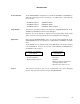
Terminology The meanings of certain terms used in this manual are listed below. Term Meaning Emulation device This is a general term that refers to the device in the emulator that is used to emulate the target device. It includes the emulation CPU. Emulation CPU This is the CPU block in the emulator that is used to execute user-generated programs. Target device This is the device that is the target for emulation.
CONTENTS CHAPTER 1 GENERAL............................................................................................................................10 1.1 System Configuration................................................................................................................................ 11 1.2 Hardware Configuration ............................................................................................................................ 13 1.3 Basic Specifications .................
LIST OF FIGURES Figure No. Title Page 1-1 System Configuration ....................................................................................................................................... 11 1-2 Basic Hardware Configuration (Using IE-78K0-NS) ......................................................................................... 13 1-3 Basic Hardware Configuration (Using IE-78K0-NS-A)......................................................................................
LIST OF TABLES Table No. Title Page 1-1 Correspondence Between Emulation Probe and Conversion Connectors ........................................................12 1-2 Basic Specifications ..........................................................................................................................................14 3-1 Main System Clock Settings..............................................................................................................................
CHAPTER 1 GENERAL The IE-780338-NS-EM1 is a development tool for efficient debugging of hardware or software when using one of the following target devices that belong to the 78K/0 Series of 8-bit single-chip microcontrollers. This chapter describes the IE-780338-NS-EM1’s system configuration and basic specifications.
CHAPTER 1 GENERAL 1.1 System Configuration Figure 1-1 illustrates the IE-780338-NS-EM1’s system configuration. Figure 1-1.
CHAPTER 1 GENERAL Notes 1. The device file is as follows. µS××××DF780338: µPD780318, 780328, 780338 Subseries The device file can be downloaded from the web site of NEC Electron Devices (http://www.ic.nec.co.jp/micro/). 2. The emulation probe SWEX-120SE-1 and conversion connectors NQPACK120SE, YQPACK120SE, and YQ-GUIDE are products of TOKYO ELETECH CORPORATION. For further information, contact Daimaru Kogyo, Ltd.
CHAPTER 1 GENERAL 1.2 Hardware Configuration Figures 1-2 and 1-3 show the IE-780338-NS-EM1’s position in the basic hardware configuration. Figure 1-2. Basic Hardware Configuration (Using IE-78K0-NS) Dedicated bus interface IE system IE-78K0-NS Host machine Interface board (sold separately) IE-780338-NS-EM1 78K0 main board Interface card (sold separately) Emulation board (this product) Emulation probe (sold separately) Figure 1-3.
CHAPTER 1 GENERAL 1.3 Basic Specifications The IE-780338-NS-EM1’s basic specifications are listed in Table 1-2. Table 1-2. Basic Specifications Parameter Description Target device µPD780318, 780328, 780338 Subseries System clock 10.0 MHz Main system clock supply External: Clock input from the target system via an emulation probe Internal: Clock mounted on the emulation board (10.
CHAPTER 2 PART NAMES This chapter introduces the parts of the IE-780338-NS-EM1 main unit. The packing box contains the emulation board (IE-780338-NS-EM1), FG cable, packing list, user’s manual, and guarantee card. If there are any missing or damaged items, please contact an NEC sales representative. Fill out and return the guarantee card that comes with the main unit.
CHAPTER 2 PART NAMES 2.1 Parts of Main Unit Figure 2-1.
CHAPTER 3 INSTALLATION This chapter describes methods for connecting the IE-780338-NS-EM1 to the IE-78K0-NS or IE-78K0-NS-A, emulation probe, etc. Mode setting methods are also described. Caution Connecting or removing components to or from the target system, or making switch or other setting changes must be carried out after the power supply to both the IE system and the target system has been switched OFF.
CHAPTER 3 INSTALLATION 3.1 Connection (1) Connection with IE-78K0-NS or IE-78K0-NS-A main unit See the IE-78K0-NS User’s Manual (U13731E) for a description of how to connect the IE-780338-NS-EM1 to the IE-78K0-NS. See the IE-78K0-NS-A User’s Manual (U14889E) for a description of how to connect the IE-780338-NS-EM1 to the IE-78K0-NS-A. (2) Connection with emulation probe The following shows how to connect the emulation probe to the IE-780338-NS-EM1.
CHAPTER 3 INSTALLATION <2> Connect the emulation probe SWEX-120SE-1 to CN5 of the IE-780338-NS-EM1. Figure 3-2. Emulation Probe Connection Emulation probe SWEX-120SE-1 (sold separately) CN5 FG cable (supplied with IE-780338-NS-EM1) Emulation board IE-780338-NS-EM1 Main board of IE-78K0-NS (sold separately) or IE-78K0-NS-A (sold separately) <3> Unfasten one of the screws on the metal board on the probe side of the IE-78K0-NS or IE-78K0-NS-A and connect and screw on the tip of the FG cable. Figure 3-3.
CHAPTER 3 INSTALLATION 3.2 Clock Settings 3.2.1 Overview of clock settings The main system and subsystem clocks to be used during debugging can be selected from (1) to (3) below. (1) Clock that is already mounted on emulation board (2) Clock that is mounted by user (3) External clock If the target system includes an internal clock, select either (1) Clock that is already mounted on emulation board or (2) Clock that is mounted by user.
CHAPTER 3 INSTALLATION (1) Clock that is already mounted on emulation board (a) For main system clock A crystal oscillator (X1) is already mounted on the emulation board. Its frequency is 10.0 MHz. Figure 3-5.
CHAPTER 3 INSTALLATION (2) Clock that is mounted by user The user is able to mount any clock supported by the set specifications on the IE-780338-NS-EM1. (a) For main system clock Remove the crystal oscillator (X1) that is already mounted on the emulation board, and mount either the parts board on which the resonator to be used is mounted or an oscillator. This method is useful when using a different frequency from that of the pre-mounted clock. Figure 3-7.
CHAPTER 3 INSTALLATION (3) External clock An external clock connected to the target system can be used via an emulation probe. Figure 3-9. When Using an External Clock IE-78K0-NS or IE-78K0-NS-A Target system IE-780338-NS-EM1 Emulation probe Clock generator (to be used) Remark The clock supplied by the target system’s clock generator (encircled in the figure) is used. 3.2.2 Main system clock settings Table 3-1.
CHAPTER 3 INSTALLATION (2) When using clock mounted by user Execute the settings described under either (a) or (b), depending on the type of clock to be used. When starting the integrated debugger (ID78K0-NS), open the configuration dialog box and select “Internal” in the area (Clock) for selecting the CPU clock source (this selects the emulator internal clock).
CHAPTER 3 INSTALLATION <2> Prepare the IE-780338-NS-EM1. <3> Remove the crystal oscillator that is mounted in the IE-780338-NS-EM1’s X1 socket. <4> Connect the parts board (from <1> above) to the X1 socket from which the crystal oscillator was removed in <3> above. Check the pin 1 mark to make sure the board is mounted in the correct direction. <5> Make sure that the parts board is wired as shown in Figure 3-10 above. <6> Connect the IE-780338-NS-EM1 to the IE-78K0-NS or IE-78K0-NS-A.
CHAPTER 3 INSTALLATION (b) When using a crystal oscillator • Items to be prepared • Crystal oscillator (see pinouts shown in Figure 3-11) Figure 3-11. Crystal Oscillator (When Using Main System Clock or User-Mounted Clock) VCC NC GND CLOCK OUT <1> Prepare the IE-780338-NS-EM1. <2> Remove the crystal oscillator that is mounted in the IE-780338-NS-EM1’s X1 socket. <3> Mount the crystal oscillator prepared by the user in the X1 socket from which the crystal oscillator was removed in <2> above.
CHAPTER 3 INSTALLATION The above steps configure the following circuit and enable supply of the clock from the mounted resonator to the emulation device. VCC IE-78K0-NS or IE-78K0-NS-A side (Emulation device) Crystal oscillator X1 LVCC HSK120 A Y B VHC157 (3) When using external clock No hardware settings are required for this situation.
CHAPTER 3 INSTALLATION 3.2.3 Subsystem clock settings Table 3-2. Subsystem Clock Settings Frequency of Subsystem Clock to Be Used IE-780338-NS-EM1 IE-78K0-NS or IE-78K0-NS-A X2 Socket JP8 When using clock (XT1) that is already mounted on emulation board 32.768 kHz 6 to 8 shorted When using clock mounted by user Other than 32.
CHAPTER 3 INSTALLATION Figure 3-13. Connections on Parts Board (When Using Subsystem Clock or User-Mounted Clock) Parts board (X2) 1 14 2 13 3 12 4 11 5 10 6 7 Pin No. Connection 2-13 Capacitor CA 3-12 Capacitor CB 4-11 Ceramic resonator or crystal resonator 9 5-10 Resistor Rx 8 8-9 Short Circuit diagram 10 MΩ HCU04 HCU04 5 Rx 10 4 3 CB 12 Remark 98 CLOCK OUT 11 13 CA 2 The sections enclosed in broken lines indicate parts that are attached to the parts board.
CHAPTER 3 INSTALLATION <3> Make sure that the parts board (X2) is wired as shown in Figure 3-13. <4> Remove the parts board that is mounted in the IE-780338-NS-EM1’s X2 socket. <5> Connect the parts board from <2> above to the socket from which the parts board was removed (from <4> above). Check the pin 1 mark to make sure the board is mounted in the correct direction. <6> Connect the IE-780338-NS-EM1 to the IE-78K0-NS or IE-78K0-NS-A.
CHAPTER 3 INSTALLATION (b) When using a crystal oscillator • Items to be prepared • Crystal oscillator (see pinouts shown in Figure 3-14) Figure 3-14. Crystal Oscillator (When Using Subsystem Clock or User-Mounted Clock) VCC NC GND CLOCK OUT <1> Prepare the IE-780338-NS-EM1. <2> Remove the parts board that is mounted in the IE-780338-NS-EM1’s X2 socket. <3> Mount the crystal oscillator prepared by the user in the X2 socket from which the parts board was removed in <2> above.
CHAPTER 3 INSTALLATION The above steps configure the following circuit and enable supply of the clock from the mounted oscillator to the emulation device. IE-78K0-NS or IE-78K0-NS-A side (Emulation device) +5 V 14 Parts board 1 3 5 Crystal oscillator 8 JP8 Target system 2 4 6 7 Remarks 1. The sections enclosed in broken lines indicate the parts that are attached to the parts board. 2. There is JP8 on the IE-78K0-NS or IE-78K0-NS-A.
CHAPTER 3 INSTALLATION 3.3 Mask Option Setting 3.3.1 LCD booster When shipped, an LCD drive booster is mounted on the parts board in the LCD MOPT (IC2) socket of the IE780338-NS-EM1. To change the LCD drive booster, mount the resistors or capacitors necessary for the parts board or others provided with this product in the LCD MOPT socket. Figure 3-16 shows the LCD drive booster. Caution The booster on the target system cannot be used. Figure 3-16. LCD MOPT Socket (IC2) CAPL 1 16 CAPH C1 N.C.
CHAPTER 3 INSTALLATION 3.4 External Trigger Connect the external trigger to the IE-780338-NS-EM1’s check pins EXTOUT and EXTIN as shown below. See the IE-78K0-NS User’s Manual (U13731E) or IE-78K0-NS-A User’s Manual (U14889E) for pin characteristics, and the ID78K Series Integrated Debugger Ver. 2.30 or Later Operation (Windows Based) User’s Manual (U15185E) for the usage methods. Figure 3-17.
CHAPTER 3 INSTALLATION 3.5 Jumper Settings on IE-78K0-NS When using the IE-780338-NS-EM1 in combination with the IE-78K0-NS, set the jumper on the IE-78K0-NS as shown below. For details of these jumper positions, refer to the IE-78K0-NS User’s Manual (U13731E). Caution If the jumpers are set incorrectly, the board may be damaged. Table 3-3.
CHAPTER 3 INSTALLATION 3.7 Low-Voltage Emulation Settings When the target system is operating on low voltage, supply the same supply voltage as the target system to the TP1 terminal pin on the main board of the IE-78K0-NS or IE-78K0-NS-A (G-780009 Board) (this processing is not necessary when the target system is operating at 5 V). At that time, set the voltage supplied to the target system to between 1.8 and 5.5 V. Caution When emulating at 4.
CHAPTER 4 DIFFERENCES BETWEEN TARGET DEVICES AND TARGET INTERFACE CIRCUITS This chapter describes differences between the target device’s signal lines and the signal lines of the IE-780338NS-EM1’s target interface circuit. Although the target device is a CMOS circuit, the IE-780338-NS-EM1’s target interface circuit consists of emulation circuits such as an emulation CPU, TTL, and CMOS-IC.
CHAPTER 4 DIFFERENCES BETWEEN TARGET DEVICES AND TARGET INTERFACE CIRCUITS Figure 4-1. Equivalent Circuit of Emulation Circuit 1 Probe side IE system side 100 Ω P47 to P40 1 MΩ 100 Ω P57 to P50 1 MΩ 100 Ω P67 to P64 µPD780009A Emulation CPU 1 MΩ LVCC HSK120 P63 to P60 30 kΩ Photocoupler 100 Ω 1 MΩ Figure 4-2.
CHAPTER 4 DIFFERENCES BETWEEN TARGET DEVICES AND TARGET INTERFACE CIRCUITS Figure 4-3. Equivalent Circuit of Emulation Circuit 3 Probe side IE system side VCC 3.3 kΩ 1.5 kΩ 100 Ω VDD0, VDD1 − Current detection + 0.1 µ F 1 MΩ µ PD393G VSS0, VSS1 X2, XT2 Open VPP Open CAPH, CAPL, VLCDC, VLC2 to VLC0 Open LVCC HC4066 RESET 100 Ω 4.7 kΩ LVCC LVCC X1 1SS123 100 Ω 4.7 kΩ µ PD780009A Emulation CPU 1SS123 LVCC XT1 100 Ω LVCC 1SS123 4.
CHAPTER 5 RESTRICTIONS AND CAUTIONS ON USE This chapter lists the restrictions and cautions on use of the IE-780338-NS-EM1. (1) Connect the in-circuit emulator to products with the following control code. In-Circuit Emulator Corresponding Control Code IE-78K0-NS L or higher IE-78K0-NS-A E or higher (2) Switching the number of the key returns (KRSEL register (FF8FH)) cannot be emulated.
APPENDIX A EMULATION PROBE PIN ASSIGNMENT TABLE Table A-1. SWEX-120SE-1 Pin Assignments (1/2) Emulation Probe CN5 Pin No. Emulation Probe CN5 Pin No.
APPENDIX A EMULATION PROBE PIN ASSIGNMENT TABLE Table A-1. SWEX-120SE-1 Pin Assignments (2/2) Emulation Probe CN5 Pin No. Emulation Probe CN5 Pin No.
APPENDIX B CAUTIONS ON DESIGNING TARGET SYSTEM Figures B-1 and B-2 show the conditions when connecting the emulation probe to the conversion connector. Follow the configuration below and consider the shape of parts to be mounted on the target system when designing a system. In the product names described in this appendix, SWEX-120SE-1, NQPACK120SE, YQPACK120SE, and YQGUIDE are products of TOKYO ELETECH CORPORATION. Figure B-1.
APPENDIX B CAUTIONS ON DESIGNING TARGET SYSTEM Figure B-2. Connection Conditions of Target System Emulation board IE-780338-NS-EM1 Emulation probe SWEX-120SE-1 Conversion connector NQPACK120SE, YQPACK120SE, YQ-GUIDE 33 mm 23 mm 48.5 mm 23 mm 38.
[MEMO] User’s Manual U16214EJ1V0UM 45
[MEMO] 46 User’s Manual U16214EJ1V0UM
Facsimile Message From: Name Company Tel. Although NEC has taken all possible steps to ensure that the documentation supplied to our customers is complete, bug free and up-to-date, we readily accept that errors may occur. Despite all the care and precautions we've taken, you may encounter problems in the documentation. Please complete this form whenever you'd like to report errors or suggest improvements to us. FAX Address Thank you for your kind support.