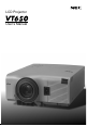
LCD Projector User’s Manual
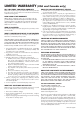
LIMITED WARRANTY GARANZIA LIMITATA Except as specified below, the warranty that may be provided by the dealer covers all defects in material or workmanship in this product. The following are not covered by the warranty: 1. Any product on which the serial number has been defaced, modified or removed. 2. Damage, deterioration or malfunction resulting from; a.
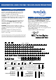
NEC Technologies Projectors Product Registration Card USA and Canada Only PLACE CORRECT POSTAGE HERE ATTN: CUSTOMER SERVICE & SUPPORT NEC TECHNOLOGIES, INC. VISUAL SYSTEMS DIVISION 1250 N. ARLINGTON HEIGHTS RD.
REGISTRATION CARD FOR NEC TECHNOLOGIES PROJECTORS THANK YOU Thank you for your purchase of an NEC Technologies projector. By purchasing an NEC projector, you are able to access the best limited warranty and service programs available in the industry today. InstaCare® service provides for the repair and return of your projector within three business days. For the ultimate in hassle free service, NEC pays for the round-trip shipping.
LIMITED WARRANTY (USA and Canada only) NEC SOLUTIONS’ PROJECTOR PRODUCTS HOW YOU CAN GET WARRANTY SERVICE NEC Solutions (America), Inc. (hereafter NEC Solutions) warrants this product to be free from defects in material and workmanship under the following terms. 1. To obtain service on your product, consult the dealer from whom you purchased the product. 2. Whenever warranty service is required, the original dated invoice (or a copy) must be presented as proof of warranty coverage.
DECLARATION OF CONFORMITY This device complies with Part 15 of FCC Rules. Operation is subject to the following two conditions. (1) This device may not cause harmful interference, and (2) this device must accept any interference received, including interference that may cause undesired operation. U.S. Responsible Party: Address: Tel. No.: NEC Technologies, Inc. 1250 N.
VT650 LCD Projector User’s Manual English E–1
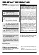
IMPORTANT INFORMATION RF Interference Precautions Please read this manual carefully before using your NEC VT650 Projector and keep the manual handy for future reference. Your serial number is located under the name plate label on the right side of your VT650. Record it here: WARNING The Federal Communications Commission does not allow any modifications or changes to the unit EXCEPT those specified by NEC Technologies in this manual.
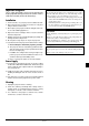
Important Safeguards CAUTION These safety instructions are to ensure the long life of your projector and to prevent fire and shock. Please read them carefully and heed all warnings. Installation 1. For best results, use your projector in a darkened room. 2. Place the projector on a flat, level surface in a dry area away from dust and moisture. 3. Do not place your projector in direct sunlight, near heaters or heat radiating appliances. 4.
Lamp Replacement • To replace the lamp, follow all instructions provided on page E-38. • Be sure to replace the lamp when the message "The lamp has reached the end of its usable life. Please replace the lamp." appears. If you continue to use the lamp after the lamp has reached the end of its usable life, the lamp bulb may shatter, and pieces of glass may be scattered in the lamp case. Do not touch them as the pieces of glass may cause injury. If this happens, contact your NEC dealer for lamp replacement.
TABLE OF CONTENTS Projector Options ................................................. E-34 Menu ............................................................... E-34 Menu Mode ................................................. E-34 Language .................................................... E-34 Source Display ........................................... E-34 No Input Display ......................................... E-35 Volume Bar .................................................
1. INTRODUCTION Introduction to the VT650 Projector • You can use the supplied wireless remote control and remote mouse receiver to operate your PC mouse wirelessly from across the room. The remote mouse receiver supports almost any PC using a USB connection or the supplied USB-to-PS/2 adapter. • You can control the projector with a PC using the PC Control port. • The contemporary cabinet design is light, compact, easy to carry, and complements any office, boardroom or auditorium.
What's in the Box? Make sure your box contains everything listed. If any pieces are missing, contact your dealer. Please save the original box and packing materials if you ever need to ship your VT650 Projector.
Getting to Know Your VT650 Projector Front/ Side Features Controls AC Input Connect the supplied power cable’s three-pin plug here.
Rear/ Side Features E O N /S TA N D Remote Sensor CA S TA P TU O W S E R E NTE R B Y NC EL M NU S E LE C T S O U R C E A U TO A D JU S T Remote Sensor Built-in Monaural Speaker (1W) Rear Foot Lamp Cover Lamp Cover Screw Rear Foot Attaching the lens cap to the bottom with the supplied string and rivet 1. Thread the string through the hole on the lens cap and then tie a knot in the string. Lens Cap String 2. Tie a knot again 3.
Top Features 9 8 O S 4 E C R U 6 NU T S JU D A T C LE E S ENTER S TU TA R S WE O P CA TO U A ME 2 NC E L N O 7 /S 5 TA D N B Y 3 1 1. Power Button (ON / STAND BY) Use this button to turn the power on and off when the power is supplied and the projector is in standby mode. NOTE: To turn off the projector, press and hold this button for minimum of two seconds. 2.
Terminal Panel Features AUDIO RGB INPUT 1 3 IN OUT OUTPUT OUT IN 4 2 PC-CONTROL S-VIDEO VIDEO 5 7 6 1. RGB Input Connector(Mini D-Sub 15 pin) Connect your PC or other RGB equipment. Use the supplied signal cable to connect to a PC. 5. Video Input (RCA) Connect a VCR, DVD player, laser disc player, or document camera here to project video. 2. RGB Monitor Output Connector (Mini D-Sub 15 pin) You can use this connector to loop your computer image to an external monitor from the RGB input source.
Remote Control Features Remote Control 1 2 OFF ON 4 NOTE: If you are using a Macintosh computer, you can click either the right-click or left-click button to activate the mouse. VIDEO S-VIDEO 5 6 7 1. Infrared Transmitter Direct the remote control toward the remote sensor on the projector cabinet. RGB AUTO ADJ. 8 MENU 10 9 E NT L SELECT 11 2. LED Flashes when any button is pressed. 3 POWER ER CA NC E 12 PJ 13 PICTURE 3.
Operating Range Remote Control Battery Installation 1. Push to open the battery cover. 2. Remove both old batteries and install new ones (AA). Ensure that you have the batteries’ polarity (+/–) aligned correctly. 7m 22feet 3. Put the battery cover back on. 30˚ 7m 7m 22feet 22feet 30˚ Do not mix different types of batteries or new and old batteries. Remote Control Precautions • • • • Handle the remote control carefully. If the remote control gets wet, wipe it dry immediately.
Using Remote Mouse Receiver The remote mouse receiver enables you to operate your computer’s mouse functions from the remote control (Computer mode). It is a great convenience for clicking through your computer-generated presentations.To return to the Projector mode, press the PJ button (lit red). Connecting the remote mouse receiver to your computer If you wish to use the remote mouse function, connect the mouse receiver and computer.
Switching Operation Mode between Computer and Projector The SELECT, ENTER, and CANCEL buttons shown on the drawing work as a computer mouse in the Computer mode. In the Computer mode the PJ button is not lit. • When any one of the POWER ON, OFF, MENU, HELP, or MAGNIFY button is pressed, the PJ button lights red to indicate that you are in the Projector mode, which allows the projector menu operation using the SELECT, ENTER or CANCEL buttons.
2. INSTALLATION This section describes how to set up your VT650 projector and how to connect video and audio sources. Setting up Your Projector Your VT650 Projector is simple to set up and use. But before you get started, you must first: 1. Determine the image size. 2. Set up a screen or select a non-glossy white wall onto which you can project your image. 4. Move the projector left or right to center the image horizontally on the screen. 5.
Distance Chart Throw Distance Screen (inch) C Width Screen Center Lens Center Screen Bottom D Screen Size (Diagonal) Height B α 2.3” (58.
Ceiling Installation Screen Top VIDEO OUT IN α OUTPUT IN OUT RGB INPUT Lens Center Projector feet 2.3” (58.
Wiring Diagram Macintosh or Compatibles (Desktop type or notebook type) Monitor RGB INPUT AUDIO RGB OUTPUT VCR, DVD Player or LaserDisc Player IN OUT OUT IN IBM VGA or Compatibles (Desktop type or notebook type) PC CONTROL S-VIDEO VIDEO Signal cable (supplied) To mini D-Sub 15-pin connector on the projector. It is recommended that you use a commercially available distribution amplifier if connecting a signal cable longer than the supplied cable.
Connecting Your PC Signal cable (supplied) To mini D-Sub 15-pin connector on the projector. It is recommended that you use a commercially available distribution amplifier if connecting a signal cable longer than the supplied one.
Connecting Your Macintosh Computer Macintosh (Notebook type) Signal cable (supplied) RG RG INP B UT BI NP UT AU AU DIO Audio cable (not supplied) OU TP UT PC -CO NT RO L DIO IN OU T OU T IN S-V IDE O VID EO Macintosh (Desktop type) NOTE: The new Macintosh computer such as G3 will have the 15 pin HD connector. The VT650's "Plug and Play" data will be downloaded to the Macintosh. Therefore, the Mac adapter will not be necessary.
Connecting an External Monitor Signal cable (supplied) RG RG INP B UT BI NP UT AU DIO OU TP UT PC -CO NT RO L RG AU DIO IN IN OU T OU T IN S-V IDE O BO UT PU VID EO T External monitor Audio cable (not supplied) DIO AU You can connect a separate, external monitor to your VT650 to simultaneously view on a monitor the image you're projecting. To do so: 1. Turn off the power to your projector, monitor and computer. 2.
Connecting Your DVD Player DVD player Component video cable RCA 3 (not supplied) Cr Cb Red Blue Green Y L R White Red RG RG INP B UT Red Blue Red Green Blue Green BI NP UT AU DIO OU TP UT PC -CO NT RO L IN OU T OU T IN S-V IDE O VID EO Optional 15-pin-to-RCA (female) 3 cable (ADP-CV1) Audio Equipment Audio cable (not supplied) L R White Red You can connect your projector to a DVD player with component outputs or Video output. To do so, simply: 1.
Connecting Your VCR or Laser Disc Player VCR/ Laser disc player RG INP B UT AU DIO OU TP UT IN SPC-V IDNTE -CO OL OU RO S-video cable (not supplied) L R OU T T IN S-V IDE O VID VID EO EO White Red Document camera Audio equipment VID L EO R White Red Video cable (not supplied) Audio cable (not supplied) Use common RCA cables (not provided) to connect your VCR, laser disc player or document camera to your projector. To make these connections, simply: 1.
3.OPERATION This section describes how to select a computer or video source, how to adjust the picture, and how to customize the menu or projector settings. General Controls Before you turn on your projector, ensure that the computer or video source is turned on and that your lens cap is removed. 4. Turning off the Projector First press the “ON/STAND BY” button on the projector cabinet or the “POWER OFF” button on the remote control for a minimum of two seconds. The power indicator will glow orange.
About Startup Screen (Menu Language Select screen) When you first turn on the projector, you will get the Startup screen.This screen gives you the opportunity to select one of the seven menu languages: English, German, French, Italian, Spanish, Swedish and Japanese. To select a menu language, follow these steps: 1. Use the or for the menu. buttons to select one of the seven languages Menu Language Select Please select a menu language. English Wählen Sie bitte die Menü Sprache aus.
Adjusting the Image Size and the Focus To adjust the projector’s focus or to zoom in and out use the Focus ring or Zoom lever on the lens. RG INP B UT AU D OU TP UT IN PC -CO NTR OU T OL S-V IDE O VID Zoom lever Focus ring Enlarging and Moving a Picture You can enlarge the area you want up to 400 percent. To do so: Adjust the image size up to 400 percent. MAGNIFY MAGNIFY While the picture is enlarged, you can move it using the “Select” , , , or button.
Geometrical Correction If the image is distorted or not displayed correctly on the screen, do the following. Each of the feet height can be changed up to 1 mm or at angles up to 1 degree. Raise the projector height using the adjustable tilt-foot. Use keystone correction for proper adjustment. See page E-31. Using the Menus Rotate the projector to make the image square to the screen. 1. Press the “Menu” button on the remote control or the projector cabinet to display the Menu.
Menu Tree Basic/ Advanced Menu Sub Menu Basic Menu RGB Source Select Video Picture S-Video Volume Image Options Projector Options Picture Brightness 0 Contrast 0 Color 0 Source Select Hue 0 Picture Sharpness 0 Information Advanced Menu Volume Image Options Color Management Volume 0 Projector Options (Toutes) Information Items Normal/Eco Keystone Factory Default Aspect Ratio Position/Clock Resolution Video Filter Gamma Correction All Data/Current Signal Lamp Mode Advanced Opti
Menu Elements Title bar Tab Setup Highlight Page1 Page2 Page3 Orientation Desktop Front Cinema Position Top Background Logo Page4 Solid triangle Slide bar Color Correction(User Adjust) Menu Menu mode Basic Color Tune 0 Language English Yellow 0 0 0 Source Display On Off Magenta No Input Display On Off Cyan Volume Bar On Off White Keystone Bar On Off On Off Filter Clean Message Menu Display Time Auto 45 Sec On Off Radio button ○ ○ ○ ○ ○ ○ ○ ○ ○ ○ ○ ○ ○ ○ ○ ○ ○ ○
Menu Descriptions & Functions Volume Adjusts the sound level of the projector. Source Select RGB Volume Video 0 S-Video Enables you to select a video source such as a VCR, DVD player, laser disc player, computer or document camera depending on what is connected to your inputs. Press the “Select” button on the projector cabinet or your remote control to highlight the menu for the item you want to adjust. NOTE:You can display the volume bar without opening the menu.
Aspect Ratio: Lamp Mode Aspect Ratio Lamp Mode Normal Normal Eco This feature enables you to select two brightness modes of the lamp: Normal and Eco modes. The lamp life can be extended up to 3000 hours by using the Eco mode. Normal Mode: This is the default setting. This setting consumes maximum current from the AC input and results in the most light output. Eco Mode: Select this mode to extend the lamp life by up to 150%.
Position/ Clock (when Auto Adjust is off): Video Filter (when Auto Adjust is off): Position/Clock Horizontal Vertical Video Filter 100 Off Less More 50 Clock 800 Phase 50 This function reduces video noise. Off: The low-pass filter is not applied. Less: The low-pass filter is applied weakly. More: The low-pass filter is applied strongly. Screen adjustments are possible even when the filter is on.
Color Management White Balance (Advanced mode) Gamma Correction White Balance Color Correction Brightness Red 0 Brightness Green 0 Brightness Blue 0 Contrast Red 0 Contrast Green 0 Contrast Blue 0 White Balance Gamma Correction (Advanced mode) Gamma Correction Graphic Linear Black Enhance Use the or buttons to choose one mode from three options.
When this feature is turned on, the “No Input” message will appear if there is no signal present. Setup Enables you to set operating options. [Page1] This option turns on or off the volume bar when you adjust the sound volume using VOL+/-(up and down) button. On: You can increase or decrease the sound volume with the volume bar on screen. Page1 You can increase or decrease the level with the keystone bar on screen.
[Page 3] (Advanced mode) [Page 4] (Advanced mode) Setup Setup Page1 Page2 Page1 Page2 Page3 Page3 Page4 Auto Adjust On Off Auto Start On Off Power Management On Off Communication Speed 19200bps Power Off Confirmation On Off Control Panel Key Lock Unlock Keystone Save On Off Clear Lamp Hour Meter Default Source Select Default Source Page4 Select RGB Clear Filter Usage When “Auto Adjust” is set to “On”, the projector automatically determines the best resolution f
To lock the cabinet buttons: 1) Use the Select or button to select “Control Panel Key Lock” and press the ENTER button. The submenu will be displayed. 2) Use the Select or button to select “Lock” and press the ENTER button. The following confirmation screen will be displayed. Lock Are you sure ? Information Displays the status of the current signal and lamp usage. This dialog box has three pages.
4. MAINTENANCE This section describes the simple maintenance procedures you should follow to replace the lamp and clean the filters. 3. Insert a new lamp housing until the lamp housing is plugged into the socket. CAUTION Replacing the Lamp Do not use a lamp other than the NEC replacement lamp (VT50LP). Order this from your NEC dealer. After your lamp has been operating for 2000 hours (up to 3000 hours in Eco mode) or longer, the “Status” light in the cabinet will go on and the message will appear.
Cleaning or Replacing the Filters A U TO A D JU S T The air-filter sponge keeps the inside of the VT650 Projector free from dust or dirt and should be cleaned after every 100 hours of operation (more often in dusty conditions). If the filter is dirty or clogged, your projector may overheat. To replace the air-filter: 1. Remove the filter cover by pushing up on the catch of the cover until you feel it detach.
5. TROUBLESHOOTING This section helps you resolve problems you may encounter while setting up or using the projector. Power/ Status Light Messages Condition Power Indicator Status Indicator Note Standby Steady orange – – Cooling down Blinking green – Blinks green for 60 seconds Lamp in Normal mode Steady green – – Lamp in Eco mode Steady green Steady green – One minute after lamp is turned on Blinking green Depending Lamp mode Do not turn off the projector during this condition.
6. SPECIFICATIONS This section provides technical information about the VT650 Projector’s performance. Model Number VT650 Optical LCD Panel 0.9” p-Si TFT active-matrix with Micro Lens Array 1024 768 dots Lens Manual zoom, manual focus F1.7 – 2.0 Lamp f=33.5 – 40.2 mm 160W NSH lamp (130W in Eco mode) The lamp is warranted for 2000 hours of operation time within 6 months. Image Size 25 – 300 inches (0.64 – 7.62 m) diagonal Projection Distance 3.5 – 36.6 ft (1.1 – 11.
Cabinet Dimensions VT650 243.1 (9.57") POWER ON/STAND BY STATUS CAN ER E NT CE L SELECT MENU AUTO ADJUST 283.6 (11.17") SOURCE 12.88 (0.51") AUDIO OUT IN IN OUT OUTPUT VIDEO RGB INPUT PC-CONTROL S-VIDEO Lens center 33.25 (1.31") 48.9 (1.93") 102.5 (4.03") Lens center 14 (0.
D-Sub Pin Assignments Mini D-Sub 15 Pin Connector 5 4 3 2 1 10 9 8 7 6 15 14 13 12 11 Pin No. Signal Level Video signal : 0.
Compatible Input Signal List Signal # # # # # # # # # # # # # # # # # # # # # NTSC PAL SECAM VESA IBM MAC MAC MAC VESA VESA IBM VESA IBM VESA IBM IBM VESA VESA VESA VESA VESA MAC VESA VESA VESA IBM MAC VESA VESA VESA MAC SUN SGI VESA SGI VESA MAC MAC HP SUN VESA VESA HDTV (1080i)(1125i) HDTV (720p)(750p) SDTV (480p)(525p) SDTV (480i)(525i) VESA VESA VESA VESA Resolution ( Dots ) 768 640 640 640 640 640 640 640 640 640 720 720 720 720 800 800 800 800 800 832 1024 1024 1024 1024 1024 1024 1024 1152 1152 1
PC Control Codes Cable Connection Communication Protocol Baud rate: 19200 bps Function Code Data Data length: 8 bits POWER ON 02H 00H 00H 00H 00H 02H Parity: No parity POWER OFF 02H 01H 00H 00H 00H 03H Stop bit: One bit INPUT SELECT RGB 02H 03H 00H 00H 02H 01H 01H 09H X on/off: None Full duplex INPUT SELECT VIDEO 02H 03H 00H 00H 02H 01H 06H 0EH INPUT SELECT S-VIDEO 02H 03H 00H 00H 02H 01H 0BH 13H PICTURE MUTE ON 02H 10H 00H 00H 00H 12H PICTURE MUTE OFF 02H 11H 00H 00H 00H 13H SOUND
Printed in China 7N8P1111