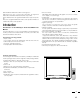
Multimedia Monitor User's Manual R 37 Plus 37 Plus R R 37 Plus 37 Plus NEC Technologies, Inc. 1250 N. Arlington Heights Road, Suite 500 Itasca, Illinois 60143-1248 MultiSync is a registered trademark of NEC Technologies, Inc. in the U.S.A. NEC is registered trademark of NEC Corporation. 1993 by NEC Technologies, Inc.
DOC compliance Notice CAUTION RISK OF ELECTRIC SHOCK DO NOT OPEN CAUTION: TO REDUCE THE RISK OF ELECTRIC SHOCK, DO NOT REMOVE COVER. NO USER-SERVICEABLE PARTS INSIDE. REFER SERVICING TO QUALIFIED SERVICE PERSONNEL. This symbol warns the user that uninsulated voltage within the unit may have sufficient magnitude to cause electric shock. Therefore, it is dangerous to make any kind of contact with any part inside of this unit.
ATTENTION RISQUE D’ELECTROCUTION NE PAS OUVRIR MISE EN GARDE: DOC avis de conformation Cet appareil numérigue de la classe A respecte toutes les exigences du Réglement sur le Matériel Brouilleur du Canada. AFIN DE REDUIRE LES RISQUES D’ELECTROCUTION, NE PAS DEPOSER LE COUVERCLE, IL N’Y A AUCUNE PIECE UTILISABLE A L’INTERIEUR DE CET APPAREIL. NE CONFIER LES TRAVAUX D’ENTRETIEN QU’A UN PERSONNEL QUALIFIE.
LIMITED WARRANTY NEC Multimedia Monitor Products NEC Technologies, Inc.(hereafter NECTECH)warrants this product to be free from defects in material and workmanship under the following terms. HOW LONG IS THE WARRANTY Parts and labor are warranted for (1) One Year and CRT’s for (1) One year from the date of the first customer purchase. WHO IS PROTECTED This warranty may be enforced only by the first purchaser.
CONTENTS 1. Introduction Introduction to the MultiSync XP37 Plus/XM37 Plus ............................................................... 1 Feature Highlights ...................................................................................................................... 1 2. Part Names and Functions Front View / Rear View ............................................................................................................. 3 Terminal Board ....................................................
1 OSM and IPM are trademarks of NEC Technologies, Inc. IBM PC/AT, PS/2, VGA, S-VGA, 8514/A and XGA are registered trademarks of International Business Machines Corporation. Apple and Macintosh are registered trademarks of Apple Computer, Inc. Microsoft is a registered trademark of Microsoft Corporation. Windows is a trademark of Microsoft Corporation.
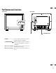
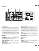
3 Part Names and Functions Front View Rear View POWER ON OFF DEGAUSS VIDEO 1 VIDEO 2 RGB 1 POSITION / CONTROL RGB 2 PROCEED EXIT SCAN WIDTH HEIGHT SIDE PIN NORMAL NORMAL BRIGHT CONTRAST MUTE VOLUME STANDBY /POWER 3 MULTIMEDIA MONITOR RD-346E POWER 2 79644641 1 VIDEO 1 VIDEO 2 RGB AUDIO RGB 1 REMOTE EXTERNAL CONTROL THROUGHPUT BNC BNC S IN IN THROUGH OUT THROUGH OUT R S VIDEO 1 IN L (MONO ) RGB PROCEED 1 IN/OUT EXIT IN 2 THROUGH OUT THROUGH OUT HIGH 2 DIP SW 75Ω ON
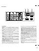
5 Terminal Board 6 7 VIDEO 1 VIDEO 2 RGB AUDIO RGB 1 REMOTE EXTERNAL CONTROL THROUGHPUT BNC BNC S S THROUGH OUT IN L (MONO ) RGB PROCEED 1 2 2 EXIT THROUGH OUT THROUGH OUT THROUGH OUT VIDEO 1 IN/OUT IN IN IN R 5 HIGH DIP SW 75Ω ON RGB 2 HIGH 75Ω AUDIO R R L (MONO ) HIGH 75Ω AUDIO L (MONO ) R IN IN THROUGH OUT THROUGH OUT G B H/CS SPEAKER SELECT V INT IN EXT EXT SPEAKER L (MONO ) RIGHT 12345678 AC IN LEFT SPEAKRES MUST HAVE MORE THAN 5WATT RATING INPE
7 Terminal Board A 0 VIDEO 1 VIDEO 2 8 9 RGB AUDIO RGB 1 REMOTE EXTERNAL CONTROL THROUGHPUT BNC BNC S S THROUGH OUT IN L (MONO ) RGB PROCEED 1 2 2 EXIT THROUGH OUT THROUGH OUT THROUGH OUT VIDEO 1 IN/OUT IN IN IN R HIGH DIP SW 75Ω ON RGB 2 HIGH 75Ω AUDIO R R L (MONO ) HIGH 75Ω AUDIO L (MONO ) R IN IN THROUGH OUT THROUGH OUT G B H/CS SPEAKER SELECT V INT IN EXT EXT SPEAKER L (MONO ) RIGHT 12345678 AC IN LEFT SPEAKRES MUST HAVE MORE THAN 5WATT RATING I
9 Terminal Board VIDEO 1 VIDEO 2 RGB AUDIO RGB 1 REMOTE EXTERNAL CONTROL THROUGHPUT BNC BNC S S THROUGH OUT L (MONO ) RGB PROCEED 1 2 2 EXIT THROUGH OUT THROUGH OUT THROUGH OUT VIDEO 1 IN/OUT IN IN IN R IN HIGH DIP SW 75Ω ON RGB 2 HIGH 75Ω AUDIO R R L (MONO ) HIGH 75Ω AUDIO L (MONO ) R IN IN THROUGH OUT THROUGH OUT G B H/CS 12345678 SPEAKER SELECT V INT IN EXT AC IN EXT SPEAKER L (MONO ) RIGHT LEFT SPEAKRES MUST HAVE MORE THAN 5WATT RATING INPEDANCE 8 O
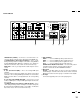
Remote Control Unit NOTE: When not in use the remote control unit is conveniently stowed in the holder on the rear panel. 1 POWER ON/OFF Press POWER ON to turn the monitor on when the STANDBY/POWER indicator is lit red. Press POWER OFF to turn the monitor off and the monitor will go into the standby condition. 2 POWER OFF ON DEGAUSS VIDEO 1 VIDEO 2 RGB 1 POSITION / CONTROL Press to demagnetize the picture tube in the manual operation. See also RGB 2 PROCEED EXIT 4 1 2 DEGAUSS 3 5 6 page 27.
13 Raster Control 7 WIDTH ( + / -) Adjusts the horizontal size of the image. 8 HEIGHT ( + / -) Adjusts the vertical size of the image. 9 SIDE PIN ( + / -) Adjusts the curvature of the edges of the left and right side of the display POWER OFF ON DEGAUSS image either inward or outward.
15 Battery Installation and Replacement The remote control is powered by two 1.5V AA batteries. 1. Turn the remote control unit upside down. Press down on the battery compartment grip and slide the compartment in the direction of the arrow. 2. Install the two new batteries, making sure that their polarity matches the (+) (-) diagrams inside the battery compartment. Incorrect polarity could damage the remote control unit. 3. Close the battery compartment cover.
17 Set the No. 1 pin to the ON/SHORT position when sync on green signals are necessary for synchronization with an external component. Functions of DIP SW SHORT ON When a composite signal is present, the picture may be distorted. If this happens, set the No.2 pin to the OFF/OPEN position. 1 2 3 4 5 6 7 8 OPEN Functions and Settings of DIP SW This DIP switch is used for Sync. Control, Intelligent Power Manager, External control, wireless control, and OSM control.
19 Installation Wiring Diagram Macintosh or Compatibles IBM XGA/SuperVGA/VGA or Compatibles EXTERNAL CONTROL IBM/MAC MultiCable IBM/MAC MultiCable To D-SUB 15 Pin input To D-SUB 15 Pin input To EXTERNAL CONTROL (D-SUB 15 Pin input) XP37 Plus/XM37 Plus VIDEO 1 VIDEO 2 RGB AUDIO RGB 1 REMOTE EXTERNAL CONTROL THROUGHPUT BNC BNC S S THROUGH OUT IN L (MONO ) RGB PROCEED 1 2 2 EXIT THROUGH OUT THROUGH OUT THROUGH OUT VIDEO 1 IN/OUT IN IN IN R HIGH To R,G,B,H/CS, V inputs (BNC) DIP
21 Connecting Your PC or Macintosh Computer Connecting your PC or Macintosh computer to your MultiSync XP37 Plus/ XM37 Plus via the MultiCable connection system will enable you to display your computer's screen image.
23 Daisy-chaining Your monitors The REMOTE IN/OUT terminals allow you to control monitors by one remote control. NOTE: The connection of three XP37 Plus/XM37 Plus monitors or more with THROUGH OUT (VIDEO 1 or 2) terminals may degrade image quality. To do so: When using the VIDEO inputs: THROUGH OUT (VIDEO 1) Connections 1. Connect THROUGH OUT 1 BNC or S-VIDEO 1 OUT to external components to relay the signal input at VIDEO 1 IN(BNC-type), or S-VIDEO 1 IN. 2.
25 External Speaker Connections External speakers may be connected to the monitor to reproduce sound from VIDEO 1, VIDEO 2, RGB 1 or RGB 2 signal sources. External speakers may be connected directly to the EXTERNAL SPEAKERS terminals or indirectly by connecting a stereo system amplifier to the audio outputs. If non-shielded speakers are used, they must be located a minimum of 4 feet away from the monitor. SPEAKER SELECT INT EXT Right 4 ft. 4 ft.
27 Operation Power This section describes how to select a computer or video source and how to adjust the picture and sound. General Controls Before you turn on your MultiSync XP37 Plus/XM37 Plus monitor ensure that the computer or video source is turned on. 1)To adjust: 1. Turn On The Monitor The power button is on the front panel of the monitor. By turning this switch on, the STANDBY/POWER indicator will turn to green and the monitor will become ready to use. OSM is also usable from the rear panel.
29 Direct Control Screen You can adjust the raster, visual and sound using the direct key on the remote control. To switch to another control screen, press any one of the other keys. *To end the OSM display, press EXIT. *If no key operation is made within 3 seconds, the OSM display will disappear. a. POSITION/CONTROL Press to move the image right. Press Press to move the image up. Press c. HEIGHT Press to adjust the vertical size of the image. d.
31 i. NORMAL( visual) Press to reset all the stored adjustment visual data and recall the factory preset data. When a specific control is selected, this key resets the selected visual adjustments. j. MUTE Press to turn off the sound for a short period of time; press again to restore the sound. k. VOLUME Press to increase the sound: press to decrease the sound. NOTE: When pressing a key that does not correspond to the function currently in use, the following message will be displayed on the monitor.
33 H-position/H-width/Pin-cushion Controls Group V-position/V-height/V-linearity Controls Group The H-position/H-width/Pin-cushion Controls allow you to adjust the horizontal position, horizontal size and pin-cushion of the image. The V-position/V-height/V-linearity Controls allow you to adjust the vertical position, vertical size and vertical linearity of the image. H-POSITION H-WIDTH V-POSITION V-HEIGHT : Pressing + or - moves the image horizontally right or left.
35 RGB Controls Group OSM Location/OSM Turn Off Time Control The RGB Controls allow you to adjust the color temperature and the white balance for RGB input. You can choose where you would like OSM image to appear on your screen. Selecting OSM location allows you to manually adjust the OSM menu left, right, up, or down. The OSM menu will stay on as long as it is in use. In the OSM Turn Off Time submenu, you can select how long the monitor waits after the last touch of a key to shut off the OSM menu.
37 All Visual Settings Reset Control The Reset control allows you to return image parameters to factory presets. All Raster Settings The above warning statement will appear to confirm that you do want to reset all raster settings. If you want to reset all raster settings, press PROCEED. The above warning statement will appear to confirm that you do want to reset all visual settings. If you want to reset all visual settings, press PROCEED.
39 OSM windows have the following elements: Right-oriented delta symbol : indicates further choices are available. Use the up or down keys to highlight the item. Pressing + proceeds to the selected control screen. Left-oriented delta symbol : indicates that you can exit the current control. Pressing - returns you to its original System control menus. POWER ON MODE This control allows you to set the monitor to default to any one of its inputs each time the monitor is turned on.
41 PC/External Control Function 4 3 2 1 10 9 8 7 6 15 14 13 12 11 5 PC/External Control Port Pin Assignments D-SUB 15pin (Input/Output) Pin No. 1 6 2 7 11 12 3 8 9 4 5 10 13 14 15 Signal Name No Connection Receive Data No Connection Transimit Data No Connection Clear to Send No Connection Request to Send Ground Input Select Input Select Power ON/OFF No Connection Degauss ON/OFF Signal Ground NOTE: If EXT.CTL is set to ON, only EXT.
43 Command Communication Sequence When external equipment such as a personal computer gives the command to the XP37 Plus/XM37 Plus, the XP37 Plus/XM37 Plus returns an ACK. So make sure that the external equipment receives this ACK. Command sending/receiving sequence Command External equipment (PC) XP37 Plus/XM37 Plus ACK The XP37 Plus/XM37 Plus returns an ACK if it has received the command correctly. If it has not received the command correctly due to data error, it will return nothing.
45 Troubleshooting Before arranging for service by the NEC Service Center, check the following to be sure repairs are needed. Possible Cause Problem No Picture or Sound Power cord unplugged. Plug in power cord. Power outlet inactive. Be sure wall switch is on and outlet has power. Switch to ON or connect to an active AC outlet. Power of external equipment is not ON. External equipment has been incorrectly connected. Sound OK; poor picture with VIDEO signal input.
47 Specifications Picture tube 35 inch Visual size; 37 inch CRT size (Diagonal), Type M89LAK113K 108 degree deflection Stripe trio pitch Ph 0.85 mm at center, Ph 1.05 mm at corner/Pv 0.87 mm Invar mask, Medium-short persistence phosphor Anti-static electricity coating Optical filter coating Dynamic focus RGB Input Terminals RGB 1 : : : : : D-SUB 15pin/mini D-SUB 15pin RGB 2: (R, G, B, H/CS and V) Video : Analog 0.7Vp-p/75 Ohms (Positive) Sync. : Separate Sync. TTL level, 0.7 - 4.0Vp-p/75 Ohms.........
49 Maximum Resolution RGB 1024( H) X 768(V) pixels VIDEO Horizontal: 500 lines /S-VIDEO Horizontal : 600 lines Video Bandwidth RGB: 70 MHz at-3dB VIDEO: 5 MHz at-3dB Display Area RGB : 95% Scan (Typically) VIDEO: 7% Overscan Retrace Time Horizontal: 15.75kHz: 7.0µsec, 30kHz
51 Dimensions 23.
53 Timing Charts Input Signal Reference Chart Separate Sync. VIDEO D C HORIZONTAL E B A VIDEO VERTICAL Q R S P Sync. Polarity: Positive / Negative O Composite Sync. VIDEO HORIZONTAL D C E B A VIDEO Q VERTICAL R S P O Sync.
55 Composite Sync. & Video (Sync. on Green) VIDEO HORIZONTAL B E D C A VIDEO VERTICAL P P R Q S O Sync. Polarity: Negative Recommended Sync Signal Timing Horizontal sync duty should be 3 to 30%. Horizontal sync width should exceed 0.9 µsec. Horizontal back porch should exceed 2.0 µsec at sync on green and 1.2 µsec at others except when at 15KHz. Horizontal blanking should exceed: 7.0µse at fH 15.75kHz, 3.3µsec at 30 kHz
57 Typical Input Signal Timing VGA Compatible Resolution Mac U , Quadra, or LC Compatible XGA-2 Compatible 640~ 350 720~ 400 640~ 480 720~ 350 720~ 400 640~ 480 640~ 480 Horizontal Frequency 31.469KHz 31.469KHz 31.469KHz 39.444KHz 39.444KHz 39.375KHz 35.000KHz (A) Horizontal Period 31.778µsec 31.778µsec 31.778µsec 25.352µsec 25.352µsec 25.397µsec 28.570µsec (B) Horizontal Pulse Width 3.813µsec 3.813µsec 3.813µsec 3.042µsec 3.042µsec 3.048µsec 2.
59 VGA Compatible Resolution 640~ 350 720~ 400 Mac U , Quadra, or LC Compatible XGA-2 Compatible 640~ 480 720~ 400 720~ 350 640~ 480 640~ 480 Vertical Frequency 70.080Hz 70.080Hz 59.940Hz 87.850Hz 87.850Hz 75.000Hz 66.667Hz (O) Vertical Period 14.268msec 14.268msec 16.683msec 11.383msec 11.383msec 13.333msec 15.000msec (P) Vertical Pulse Width 0.064msec 0.064msec 0.064msec 0.051msec 0.051msec 0.051msec 0.090msec (Q) Vertical Back Porch 1.716msec 0.890msec 0.793msec 1.
61 Signal Identification for Raster Preset MODE MODE1 Polarity Hor Ver - State Hor - - Ver - Frequency Hor Ver - - NEC USER PRESET PRESET YES-1 15.5-16.0KHz MODE2 30-33KHZ REMARKS YES-1 NTSC YES-2 RGB 15kHz YES-2 YES-3 PAL/SECAM - - - YES-3 YES-4 VESA I-Standard 640x480(31.5KHz/60Hz) - - - - - YES-4 - (H) H - - - YES-5 IBM 640x350(31.5KHz/71Hz) NEG NEG -(H) POS POS POS NEG NEG POS (H) H - - - YES-6 IBM 640x400(31.
63 Service and Support Policies NEC Technologies is committed to providing the highest quality service and support for your MultiSync presentation monitor. A customer service group that is dedicated to the support of this product line is available to provide a single point of contact for technical support, trouble shooting, service and repair issues.
20