BOOSTER installation guide Prox-Booster Smartcard-Booster 2G Smartcard-Booster Ultimate 19-05-2015 | v4.
BOOSTER 2G | USER GUIDE Content CONTENT 1 INTRODUCTION _______________________________________________________ 3 2 INSTALLATION ________________________________________________________ 2.1 DIMENSIONS ___________________________________________________ 2.2 TEMPERATURE CONSIDERATIONS __________________________________ 2.3 SOLAR CONTROL WINDSHIELDS ___________________________________ 2.
BOOSTER 2G | USER GUIDE Introduction 1 INTRODUCTION The Prox-Booster and Smartcard-Boosters are dual ID tags enabling simultaneous identification of the inserted personal ID card and the embedded vehicle ID resulting in rapid driver and vehicle monitoring. The Prox-Booster Tacho additionally sends the tacho-counter value, which relates to the travelled distance of the vehicle.
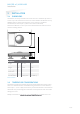
BOOSTER 2G | USER GUIDE Installation 2 INSTALLATION 2.1 DIMENSIONS The Boosters are easily mounted to the inside of the car’s windshield by means of suction cups. Users should ensure the visual contact between the Booster and any TRANSIT reader is unobstructed with items such as stickers or metallized windshields (see also chapter 2.3 about solar control windshields). Note that the Booster's suction cups must be faced toward the reader to achieve maximum reading distance.
BOOSTER 2G | USER GUIDE Installation 2.3 SOLAR CONTROL WINDSHIELDS From 1997 onwards several car manufacturers introduced vehicles with solar control windshields. The solar control windshields are equipped with a metalized coating, which can block the TRANSIT signal from the Booster mounted on the inside of the windshield of the vehicle. Most of these windshields have a metal free zone where transponders can be mounted.
BOOSTER 2G | USER GUIDE Identifying The Booster With A TRANSIT 3 IDENTIFYING THE BOOSTER WITH A TRANSIT 3.1 HOW TO USE THE BOOSTER Place the Booster on the inside of the windscreen of your vehicle as described in chapter 2. The driver inserts his personal identification card and activates the Booster’s button. A beep should indicate that the card was successfully read. A low beep indicates that card reading failed. The TRANSIT reader can identify your card up to a distance of 10 meters (=33 ft).
BOOSTER 2G | USER GUIDE Identifying The Booster With A TRANSIT Example driver-id = 871111111117100944, TXD = Z00000000000000871111111117100944 C R L F P PR RP PR R If 'Standard-length' is configured, the following message is transmitted to the host. TXD = U00871111111117100944 C R L F P PR RP PR Event identifier ('Z' or 'U'). Driver-id (20 or 32 digits). 3.
BOOSTER 2G | USER GUIDE Identifying The Booster With A TRANSIT How to calculate the vehicle's travelled distance. • Get the actual tacho counter value (= Tn ) • Calculate travelled distance by using the following formula: Dn = • (Tn − T1 ) K Calculate the current mileage by using the following formula: M n = Dn + M 1 .
BOOSTER 2G | USER GUIDE Smartcard Configuration 4 SMARTCARD CONFIGURATION The Smartcard-Booster can be configured by means of a configuration card. This configuration card is a Mifare Classic 1K or 4K card that is programmed with the configuration settings. Configuration is only required if the factory default settings are not sufficient. The default settings are described in chapter 4.2.3. 4.
BOOSTER 2G | USER GUIDE Smartcard Configuration 4.2.1 TARGET DEVICE The Booster Configuration software can be used to configure a number of different devices. The user-interface is adapted to the selected target device. Select in the ‘Target’ menu which device you are about to configure. • • • • Smartcard-Booster Transition Booster Prox Booster EM4x50 MTR Module not covered in this manual see chapter 5 4.2.
BOOSTER 2G | USER GUIDE Smartcard Configuration standard-length is selected in the configuration). Active mode Two activation modes are possible: Switched or Always-on. The setting can only be changed when the Booster originally was in switched mode !!! Switched mode is selected when the operating mode is Booster (only Driver-ID). Switched mode (active for approx. 5 seconds) In switched mode the booster is active for approx.
BOOSTER 2G | USER GUIDE Smartcard Configuration Calypso Enable or disable the reading of Calypso cards. Data to read: For Calypso cards the 4-byte PUPI or information from always accessible files can be read. The Booster does not support the Calypso SAM to fully support the Calypso encrypted file system. Select one of the following choices: • PUPI (pseudo unique PICC identifier) • Calypso file data Byte order The byte order can be set to normal or reversed.
BOOSTER 2G | USER GUIDE Smartcard Configuration Example Data to read: Byte order: Page Number: Data Length: Data Offset: MIFARE UltraLight data Normal 4 8 2 Always 16 bytes are read from the card and in this example the reading starts at page 4, thus pages 4, 5, 6 and 7 are read. The first 2 bytes are skipped because the offset is set to 2. The following 8 bytes are transmitted because the configured data length is 8.
BOOSTER 2G | USER GUIDE Smartcard Configuration Reading MIFARE classic sector data The Mifare Classic 1K and 4K cards are fully supported. Also other Mifare cards which are compatible (such as Mifare Plus and SmartMX) can be used. The memory is organized in sectors with blocks. Every block consists of 16 bytes. Upon configuring the smartcard-booster for reading MIFARE DESFIRE cards, the following parameters must be specified. Sector Number Sector number to read data from (in range from 0 .. 39).
BOOSTER 2G | USER GUIDE Smartcard Configuration Reverse example Data to read: Byte order: Sector Number: Block Number: Data Length: Data Offset: MIFARE Classic sector data Reverse 2 0 10 6 The settings above will read the data below shown in blue.
BOOSTER 2G | USER GUIDE Smartcard Configuration AES Key number Key number in range from 0 to 13. Key Security authentication key. Depending upon the selected encryption method and key number. The encryption key is 16 or 24 bytes.
BOOSTER 2G | USER GUIDE Smartcard Configuration 4.2.3 DEFAULT CONFIGURATION In the table below the default configuration is shown.
BOOSTER 2G | USER GUIDE Smartcard Configuration 4.3 ROGRAM THE CONFIGURATION CARD 4.3.1 USING A SUPPORTED PROGRAMMER The software supports a few different programming devices. The NXP Pegoda, the HID OMNIKEY 5x21 and PC/SC contactless readers from the Springcard CSB6 Family (e.g. Prox 'n' Roll PC/SC). NXP Pegoda Programmer Connect the NXP Pegoda Mifare programmer to a USB port on your computer. USB drivers must be installed as described in the NXP documentation.
BOOSTER 2G | USER GUIDE Smartcard Configuration 4.3.2 USING ANOTHER PROGRAMMER If there is no supported programmer available you can use any other Mifare programmer to write the configuration into a Mifare classic card. The configuration data should be written into sector 1 and 2 of a Mifare Classic 1K or 4K card. The contents of these sectors is not explained, but can be shown by the configuration software by clicking ‘Show configuration details’ in the ‘Expert’ menu.
BOOSTER 2G | USER GUIDE Smartcard Configuration 4.4 TESTING THE CONFIGURATION The MIFARE settings can be tested before loading it into the Smartcard-Booster using a supported mifare reader. From the ‘Programmer' menu choose ‘Test configuration’. Place the Mifare card (not the config card) on the reader and click the ‘Read’ button. The reader reads the Mifare card according to the current configuration settings. The software displays the driver-id number as it will be identified by the TRANSIT.
BOOSTER 2G | USER GUIDE MTR Configuration 5 MTR CONFIGURATION The MTR Module (Multi-Technology Reader) is especially designed to read lowfrequency proximity cards and ISO compliant smartcards directly on the TRANSIT Entry reader at short range without Booster. The MTR is configured in exactly the same way as the Smartcard Booster. Refer to chapter 4 on page 9 for more information about the configuration procedure.
BOOSTER 2G | USER GUIDE Buzzer Indications 6 BUZZER INDICATIONS The Booster's built-in buzzer gives audible feedback upon various conditions. The table below describes the buzzer indications.
BOOSTER 2G | USER GUIDE Battery Replacement 7 BATTERY REPLACEMENT The Smartcard-Booster contains two replaceable non-rechargeable AAA batteries. The average lifetime of these batteries is approximately 5 years. When replacement becomes necessary follow the procedure below. • 1 Open the battery compartment. • Remove both batteries. Follow local environment protection laws / regulations for disposal of used batteries. • Replace with two new batteries.
BOOSTER 2G | USER GUIDE Technical Specifications A TECHNICAL SPECIFICATIONS Dimensions 111 x 65 x 24 mm (4.4 x 2.6 x 1.0 in) Weight 120 gram (4.2 oz) Protection IP32 Operating temperature -20°C … +85°C (-4°F … +140°F) Storage temperature -40°C … +85°C (-40°F … +140°F) Color Grey RAL 7016 / RAL 7040 Relative humidity 10% … 93% non-condensing Identification range Typically 10 meters Battery, size AAA, 1.5V 2 x Duracell Procell PC2400 Approx.
BOOSTER 2G | USER GUIDE FCC / IC Statement B FCC / IC STATEMENT Prox-Booster CGDBOOSTER4 and 1444A-BOOSTER4 Smartcard-Booster CGDBOOSTER5 and 1444A-BOOSTER5 Smartcard-Booster SB CGDBOOSTER7 and 1444A-BOOSTER7 Smartcard-Booster Ultimate CGDBOOSTER10 and 1444A-BOOSTER10 Compliance statements (part15.19) This device complies with part 15 of the FCC Rules and to RSS210 of Industry Canada.
BOOSTER 2G | USER GUIDE Disclaimer C DISCLAIMER This information is furnished for guidance, and with no guarantee as to its accuracy or completeness; its publication conveys no license under any patent or other right, nor does the publisher assume liability for any consequence of its use; specifications and availability of goods mentioned in it are subject to change without notice; it is not to be reproduced in any way, in whole or in part, without the written consent of the publisher.
BOOSTER 2G | USER GUIDE Document revision D DOCUMENT REVISION Version Date Comment 4.2 19-05-2015 Added Smartcard-Booster Ultimate 4.1 29-04-2014 HR update 4.0 13-02-2014 Layout adjusted to new corporate style.