PRELIMINARY i30 i45 !D Gate !D Hybrid Gate Firmware version 14.
Contents 1 Introduction _________________________________________________________________________________ 4 RFID Regions ______________________________________________________________________________ 5 CE WEEE __________________________________________________________________________________ 5 Battery disposal ___________________________________________________________________________ 6 2 Product overview ____________________________________________________________________________ 7 Box contents ___________
7 Servicing the installation _____________________________________________________________________ 47 Nedap Device Management ________________________________________________________________ 47 SNMP ___________________________________________________________________________________ 47 8 Troubleshooting ____________________________________________________________________________ 48 Physical installation _______________________________________________________________________ 48 Configuration _________________
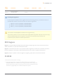
1 Introduction The Nedap FLR-line products are gates that can be equipped with Ultra High Frequency (UHF) RFID and/or 8.2 MHz RF detection technology. In addition to those technologies, it is possible to add infrared beam sensors for direction detection or customer counting. The gates are specifically designed for in-store retail applications, such as Electronic Article Surveillance (EAS), stock room to sales floor transition and goods receiving.
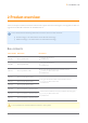
Article number Article name Technologies 9982175 ASSY FL45R RFID R3 UPGRADE-RENOS UHF RFID Model name FCC ID IC Installing the upgrade kit For the physical installation of the upgrade kit for the following products, an additional manual is available that contains instructions on how to install the upgrade kit: 9982248 - ASSY FL45R RFID R1 UPGRADE-RENOS 9982302 - ASSY FL45R RFID R2 UPGRADE-RENOS 9982175 - ASSY FL45R RFID R3 UPGRADE-RENOS This manual is for Nedap Retail certified service engineers o
that applies to electrical and electronic equipment falling under Annex IA of Directive 2002/96/EC, provided the equipment concerned is not part of another type of equipment that does not fall within the scope of this Directive. Annex IB of Directive 2002/96/EC contains an indicative list of the products, which fall under the categories set out in Annex IA of this Directive; that serves to clearly identify the producer of the equipment and that the equipment has been put on the market after 13 August 2005.
2 Product overview There are multiple variations within the FLR-line that support different technologies, and upgrade kits that can upgrade an 8.2 MHz RF installation to UHF RFID later on. In this document the following abbreviations will be used from here onwards: 'RF technology' is an abbreviation for 8.2 MHz RF technology. 'RFID technology' is an abbreviation for UHF RFID technology.
Components The FLR-line of products are based on the Renos platform. The Renos platform is developed by Nedap Retail specifically for retail applications. The FLR-line of products has several serviceable parts. These are explained in the table and highlighted in the schematic drawings. Number Component Description 1 Lights The red LED lights can be used for user feedback or alarms. 2 RF antenna The antenna is integrated in the aluminium frame.
Number Component Description The Renos unit is the main processing unit of an FLR product. It takes care of powering the system, data 6 Renos unit communication between units and with the outside world. For most products it is equipped with an RF detection engine - with the exception of the RFID-only systems used in Region 1 to be compatible with the OST platform. 7 Buzzer The buzzer can be used for user feedback or alarms.
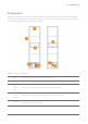
Dimensions The dimensions of the gates can be found in the drawings below. The pattern of holes in the mounting plate can be used to draw the right locations for drilling holes in the floor.
FL30R Page 11 of 55 Manual FLR-line
FL45R Page 12 of 55 Manual FLR-line
Connections In the next picture a Renos unit is displayed, with a description of all its connectors and what they are used for. Number Connector Usage 1 50 ohm Connect the Renos unit to the 50 ohm PCB. The 50 ohm PCB connects both the light and the RF antenna. 2 Infrared beams Connect to the optional infrared beam sensors. 3 Add-on Provide power and synchronization to add-ons, like the RFID reader. 4 Network IN Connected to the Network OUT of a previous Renos unit or a Power Inserter.
Number Connector 8 9 RS485 connector Buzzer connector Usage Connect to the optional Nedap RF Smart Deactivator. Connect to the included buzzer. The LED indicators on the Renos unit will be discussed later in this manual. Add-ons There are several add-ons available for the FLR-line products. The add-ons have their own manual, however, we will discuss the function of those add-ons here.
RF Smart Deactivator The RF Smart Deactivator can be used to deactivate RF labels at the checkout. When connected to a Renos system, it can be powered by a Renos system. The Renos system is also able to gather information from the deactivator, like whether the deactivator is operational or not. The RF Smart Deactivator cannot be used in systems where RFID is enabled. RF security dashboard The Renos platform has a built-in RF security dashboard.
3 Preparing the installation When preparing an installation with FLR-line products, there are a few things that should be taken into account: How much gates you would need to cover an entrance or door Where the gates will be placed in relation to the environment, to minimize interference (RF) and reflections (RFID) The number of Power Inserters that is needed to power the system Which cabling needs to be installed The firewall settings that need to be in place to enable Device Management As those requiremen
Stock room to sales floor and goods receiving For the stock room to sales floor and goods receiving roles: when there is a different door or entrance, build a separate system. It is not possible to combine gates with RFID and without RFID in one system. Either all gates should have RFID, or no gates should have RFID. Field distribution As RF and RFID are different technologies, their field distribution is different. Field distribution for RF There are two modes of operation for RF technology.
Field distribution for RFID In contrary to RF, with RFID the field is side-dependent. This means that there are two antennas inside each gate, pointing to opposite directions. If there is more than one gate in a group, there is a detection field in between gates. This is the default mode of operation. If you combine both RF and RFID in one system, we recommend to disable Edge Detection. In this way, the behaviour for both technologies is approximately the same.
Detection distance, aisle width and label-free zone The next step after understanding the field distribution, is understanding how many gates you need. This depends on the detection distance (or aisle width) of the system. There is no fixed answer to this question, it depends on many factors, like customer expectation, quality of the tags, the environment, etc. The recommendations below are based on the Nedap NT4040 (reference label) for RF, and the Nedap RFID hard tag (for RFID).
With RF Edge Detection (without RFID) We speak about 'detection distance' in this case. When RF Edge Detection is enabled, the following recommendations are in place: For the FL30R gate: a detection distance of 85 cm (2.8 ft) is recommended. For the FL45R gate: a detection distance of 100 cm (3.3 ft) is recommended. We recommend to have a RF label-free zone of more than 150 cm (4.9 ft.) from the center of the antenna behind the antenna, and 100 cm (3.3 ft.) into the store.
In addition, when normal or sliding doors are present: There should be a minimum distance of 40 cm (16 in.) between the center of the gate and the door. In addition, when a roller shutter is present: There should be a minimum distance of 70 cm (28 in.) between the center of the gate and the roller shutter.
If a power socket is less than 50 cm (19.7 in.) from the gate, the center of the gate should be aligned with the power socket. Before the installation, it is advised to gain information on the flooring that is below the antenna. If a dry-walk floor mat is used, it might have metal components that influence RF detection performance. In that case a cut needs to be made in the floor mat to break conduction between the metal components in the mat and the antenna.
Automatic tag muting The RFID reader has a maximum read throughput of around 200 tag reads per second. This throughput is used to monitor the status of the tags continuously. When many tags are placed close to or in the label-free zone, it might be that the reader is 'too busy' with those tags, compared to other tags. This will impact the system performance. If this happens, the reader will mute some tags, to have time remaining for other tags. This feature is called automatic tag muting.
Of course, it is also possible to put less Renos units on a Power Inserter. Please note that you can only use a Nedap Power Inserter (Power-over-Ethernet) to power Renos systems. It is not possible to use generic Power-over-Ethernet switches or stand-alone inserters. Make sure the Power Inserter is placed at least 1 m or 3.3 ft. from the gates. When placed closer to the gate, it might cause interference on the RF technology.
If the system should be connected to the customer network or Device Management, there also needs to be an Ethernet cable from the system to the customer network or a 3G/4G router. Ethernet cable The maximum data communication length for an Ethernet cable is 100 meter (328 ft.). Therefore we recommend the following maximum distances: The maximum cable length in between two Renos units is 100 meter (328 ft.) - even if there is a Power Inserter in between.
The RFID coax cable has a fixed length of 3.5 m (11.5 ft.) to minimize signal loss. If the cable is not run through a slit, but through a basement or other conduit please check whether the path is not longer than approximately 2.5 m (8.2 ft.). Cable number Type of cable Required for RF Required for RFID 1 Ethernet cable Yes 2 RFID coaxial cable No Yes Yes Device Management All the Renos-based products can be connected to the Nedap Device Management Service. This service provides: Monitoring.
This can be verified by connecting your laptop to the customer network, open your browser and navigate to https://api.nedapretail.com. You should see a special page there. It is also possible to do this via an HTTPS proxy, however, the remote log-in feature is not available then. For more details, please see the Knowledge Base article on Device Management. If Device Management is available at a certain site, it is possible to pre-configure a system, such that the field engineer will have an easier job.
4 Executing the installation When all the preparations are taken into account, the installation of the system can take place. The installation consists of physically mounting the system in the right orientation, installing the cabling and applying power to the system. Conduit or slit We always advise to place a conduit, as this allows easy replacement of cables when necessary. If not possible, a slit can be made as well.
Physical installation Make sure the right locations of the holes are marked on the floor, according to the dimensions sketched earlier in this document. Drill the holes. Placing a gate close to a wall If RF technology is to be used: always keep enough space to place a shielding afterwards. You will only know whether you need shielding when you are configuring the system (for example when you find too much interference during the configuration). Then follow these steps to place the nuts. 1. Clean the hole.
Always use a nylon insulation ring to insulate the gate from the floor. Number Description 1 Nut M10 (not included in installation set) 2 Retainer ring M10 (not included in installation set) 3 Nylon insulation ring M10 (included in installation set) If the gate is not properly isolated from the floor, this might cause RF interference issues.
Orientation of products Due to the orientation-sensitivity of the RFID antennas, the gates all need to be oriented in the same way. To make sure this happens, please follow the listed steps in order: 1. Place all gates with the infrared beam sensors connector facing towards the customer entrance/exit of the store. a. For the stock room to sales floor and goods receiving role: this also holds here - the gates should not face the goods delivery entrance/exit of the store. See the example below. b.
Example of EAS role Page 32 of 55 Manual FLR-line
Example of EAS role, with toilet Page 33 of 55 Manual FLR-line
Example of stock room to sales floor role Please note that when you compare stock room to sales floor role to EAS with toilet, the orientation of the gates is exactly opposite! This is due to the fact that all gates should be facing the customer entrance/exit of the store, with the exception of the toilet.
Example of goods receiving role Installing cabling and filters During the preparation phase, the exact cabling required was already determined. Now these cables can be placed. All wiring should be done according to local regulations. When cables are put in the slit or conduit, it is recommended to mark them with IN and OUT, or PREVIOUS and NEXT, as this will allow you to distinguish them from each other.
To save yourself a huge amount of frustration, please first place the filters before attaching the connectors. The other way around is not possible. Many have tried before. Filters can be ordered as spare part with Nedap. Please refer to the Nedap Retail Portal for more information. The filters that are close to a Renos unit should be placed inside the foot of the gate. If there are multiple filters in the electronics are of the gate, they should be tied together.
Please make sure that you don't make sharp bends in the RFID coaxial cable. This will have a negative impact on the performance of the system. Don't use a tool to tighten the RFID coaxial cable connectors. This is not necessary and might break the connectors. If the connector is tightened by hand, that is good enough. Status LEDs The electronics inside the unit has several status LEDs that can be used to discover the status of each part of the electronics.
Led Color Status Explanation Blinking The operating system on the Renos unit is running 4 Yellow Off The operating system on the Renos unit is not running Blinking The storage flash on the Renos unit is accessed 5 6 Green Off The storage flash on the Renos unit is not accessed On The firmware on the Renos unit is running Off The firmware on the Renos unit is not (yet) running Green Please refer to the Troubleshooting chapter later in this manual to resolve erroneous conditions.
Led Color Status Explanation Off The RFID reader is not connected to the Renos firmware Blinking slow The firmware on the RFID Reader is running 2 3 4 5 Orange Off The firmware on the RFID reader is not running On There is an error with the RFID output Off There is no error with the RFID output On The RFID output is active Blinking The reader is reading RFID labels Off The RFID output is not active On The RFID reader is powered by the Renos unit Off The RFID reader is not powered by
5 Configuring the installation To complete the configuration, the following tools are required. Mini-USB cable. Laptop with installed driver (if necessary) and recent browser. Driver installation To configure a Renos-based system, sometimes a driver needs to be installed. Please check the table below whether you need to install a driver, based on your operating system.
Connecting a laptop to the Renos unit You can connect your laptop via a Mini-USB cable to the service port on the Renos unit. You can choose any Renos unit in the system. It is advisable to use a long USB cable. This is more comfortable as you can find a good place to put your laptop (instead of on top of stairs, or on the floor next to the antenna). Besides, some laptops cause interference on the RF technology, so it is better to place them further away.
The system is connected to Device Management: you can directly enter your Nedap Retail username and password. The system is not connected to Device Management, and you don't have a Nedap Retail authentication software or hardware dongle: choose one of the following steps: If your laptop is able to connect to Device Management via a 3G dongle or Wi-Fi, you can use this option to enter your username and password. If that is not available, you can use your smartphone.
Configuration is lost Please note that when doing a factory reset, all settings and configuration of the unit are lost. The firmware version does not change. Firmware change There are three ways to change the firmware version on a Renos-based system: 1. Device Management update. The update can be executed via the Device Management service. 2. Local - single unit flash. The update can be executed by inserting a USB stick with the right firmware into the USB port. 3. Local - complete system flash.
Local - complete system flash Download the correct firmware image file from the Nedap Retail portal. Enter the configuration wizard and accept all Renos units in the system that should be updated. Press the Advanced button and follow the steps to change the firmware. One of these steps is to upload the firmware image file. Configuration is lost Please note that when using 'local - complete system flash' firmware change, all settings and configuration of the system are lost.
6 Integrating the installation with other systems It is highly recommended to integrate the FLR line product into other solutions in use at the end customer. Software integration with API's The Renos platform offers several API endpoints that deliver events. Those events include: RFID reads RFID movements RF alarms RFID alarms Infrared beam sensor events For more information please refer to the Software integration page on the Nedap Retail portal with documentation and examples.
Disable RF transmitter The IO Box cannot be used in systems where RFID is enabled. URL trigger Network-based devices that have an http-based-API can be triggered with the URL trigger mode. At this moment Axis cameras and Scope pagers are supported. A control URL (a link containing information) of this device can be triggered by an RF alarm. The URL should be created in the device. The communication can be further configured in the configuration wizard.
7 Servicing the installation When the installation has been completed and delivered, it is possible to service the installation via Nedap Device Management. Besides, we provide monitoring options locally via SNMP. Nedap Device Management Via Nedap Device Management the following features are available, when the system is connected to Nedap Device Management. System monitoring via some key metrics.
8 Troubleshooting If the system is not working correctly, please check the troubleshooting options below. If it is not possible to solve your issue, you can find support options in the next chapter. Physical installation Symptom The red LED (3) on a Renos unit is on. The red LED (3) on a Renos unit is blinking. The green LED (1) on a Renos unit is off, but there is a unit behind this unit. The red LED (3) on the RFID reader is on.
Configuration Symptom Cause Renos unit has not started yet Solution Verify the green "firmware running" LED on the Renos unit (6). If this LED is not on, verify the system has power or wait five minutes and try again. It is not possible to access the configuration web interface. Mini USB cable not attached to Renos unit and laptop Attach cable to Renos unit and laptop. Driver not installed On Windows 7 and older you manually need to install a driver to support Renos.
2. Disable all transmitters. a. If all parameters in the RF gate performance section turn green again, there is a coupling problem (the transmitter couples with a label-like object in environment). Please continue at the 'coupling problem' section. b. If all parameters in the RF gate performance section remain orange or red, there is an active interferer (another device that transmit radio waves around the 8.2 MHz RF spectrum, like another EAS system, an engine or a power supply).
If these things don't solve the problem, please contact support. Active interferer The first step is to try to locate the source of the active interferer. You can do this by unplugging electronic devices around the gate (or move them away), and see if the parameters in the 'RF gate performance' section improve, or when the average height of the spectrum is reduced. If this is the case, you have identified the active interferer. When the active interferer is known, the following solutions are possible: 1.
9 Regulatory information FCC and IC Compliance statement This device complies with part 15 of the FCC Rules and to RSS210 of Industry Canada. Operation is subject to the following two conditions: (1) this device may not cause harmful interference, and (2) this device must accept any interference received, including interference that may cause undesired operation. Changes or modifications not expressly approved by the party responsible for compliance could void the user’s authority to operate the equipment.
FCC Information to the user Note: This equipment has been tested and found to comply with the limits for a class B digital devices, pursuant to part 15 of the FCC Rules. These limits are designed to provide reasonable protection against harmful interference in a residential installation. This equipment generates, uses and can radiate radio frequent energy and, if not installed and used in accordance with the instructions, may cause harmful interference to radio communications.
10 About Nedap About At Nedap Retail, we work around the globe to deliver industry-leading products, services and solutions for our customers’ diverse needs in loss prevention, stock management and store monitoring. Our inventive thinking and collaborative spirit allows us to deliver tailor-made solutions for the fast paced retail sector. We simplify retail management while improving your customers’ shopping experience.
Last modification: 13 August 2014 15:07 N.V.