© 2003 Nedap Retail Support Netherlands Parallelweg 2d, 7141 DC Groenlo The software / hardware described in this book / file is furnished under a license agreement and may be used only in accordance with the terms of the agreement. Documentation version 1.0 Copyright Notice All Rights Reserved. Any technical documentation that is made available by Nedap Retail Support is the copyrighted work of Nedap Retail Support and is owned by Nedap Retail Support. NO WARRANTY.
Technical Support: - E-mail:support-rs@nedap.nl - H. Hammer +31 (0) 544 47 15 19 h.hammer@nedap.nl - H. Broekhuis +31 (0) 544 47 15 02 h.broekhuis@nedap.
Table of contents Technical Support: .................................................................................................................................... 3 BQ PCB ............................................................................................................................................. 5 EQ PCB ............................................................................................................................................. 7 EQ3E PCB.............................
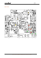
BQ PCB K203 K205 K201 K202 K204 K3 K16 K19 D25 P3 D26 D19 D16 D301 D300 K24 K23 K11 K5 5 OS/T Course 2003 © NEDAP Retail Support 2003 D311 K300
The following points can be used: K3 Oscilloscope Tx K5 Output Tx (connector 3) K9 Jumper Attenuation K11 Power Input K12 Jumper Attenuation K13 Jumper Attenuation K15 Jumper Attenuation K16 RS232 Interface Connector K21 Connector FCI K23 IO Connector K24 IO Connector K201 K202 K203 K204 K205 K300 P1 P2 P3 P4 P5 Handheld terminal RxTx Oscilloscope Rx Jumper Jumper Handheld terminal NCC Output Rx (connector 1) PA Drive Adjustment Phase Adjustment Tx Mixer Bias Adjustment Slave Data communication Rx Master
EQ PCB K203 K21 K205 K201 K202 K204 K3 K16 K19 P1 P2 D25 D18 D26 P3 D17 D19 D303 D16 D302 P4 P5 D11 D301 D300 D312 K6 K10 K23 1 K4 K5 5 7 OS/T Course 2003 © NEDAP Retail Support 2003 K301 D311 K300
The following points can be used: K3 Oscilloscope Tx K4 Output Tx (connector 4) K5 Output Tx (connector 3) K6 Synchronization In K9 Jumper Attenuation K10 Master connector K11 Power Input K12 Jumper Attenuation K13 Jumper Attenuation K15 Jumper Attenuation K16 RS232 Interface Connector K21 Connector FCI K23 IO Connector Indicator leds: D11 Mux Connector 1 TX D12 Mux Connector 2 TX D16 Lamp On Connector 3 D17 Lamp On Connector 4 D18 Lamp Overload Connector 4 D19 Lamp Overload Connector 3 D25 Sweep Lock D26 C
EQ3E PCB K203 K K201 K202 K204 K3 P1 P2 D18 P3 D17 D19 D303 D16 D302 P4 D11 D12 D301 D11 D300 D312 K6 K7 K11 1 K23 K4 K5 16 9 OS/T Course 2003 © NEDAP Retail Support 2003 K301 D311 K300
The following points can be used: K3 Oscilloscope Tx K4 Output Tx (connector 4) K5 Output Tx (connector 3) K6 Synchronization In K7 Synchronization In K9 Jumper Attenuation K11 Power Input K12 Jumper Attenuation K13 Jumper Attenuation K15 Jumper Attenuation K21 Connector FCI Indicator leds: D11 Mux Connector 1 TX D12 Mux Connector 2 TX D16 Lamp On Connector 3 D17 Lamp On Connector 4 D18 Lamp Overload Connector 4 D19 Lamp Overload Connector 3 D201 Label Alarm RxTx K24 K201 K202 K203 K204 K300 K301 P1 P2 P3
IQ PCB K203 K K205 K201 K202 K204 K3 K16 P1 P2 D25 D18 D26 P3 D17 P4 D19 D303 D16 D302 P4 P5 D12 D11 D301 D300 D312 K6 K7 1 K24 16 1 K23 16 K10 K11 K4 K5 11 OS/T Course 2003 © NEDAP Retail Support 2003 K301 D311 K300
The following points can be used: K3 Oscilloscope Tx K4 Output Tx (connector 4) K5 Output Tx (connector 3) K6 Synchronization In K7 Synchronization In K9 Jumper Attenuation K10 Master connector K11 Power Input K12 Jumper Attenuation K13 Jumper Attenuation K15 Jumper Attenuation K16 RS232 Interface Connector K19 Jumper K21 Connector FCI K23 K24 K201 K202 K203 K204 K205 K300 K301 P1 P2 P3 P4 P5 IO Connector IO Connector Handheld terminal RxTx Oscilloscope Rx Jumper Jumper Handheld terminal NCC Output Rx (co
IQ3E PCB K203 K K201 K202 K204 K3 P1 P2 D18 P3 D17 D19 D303 D16 D302 P4 D11 D12 D301 D300 D312 K6 K7 1 K24 16 1 K23 16 K11 K4 K5 13 OS/T Course 2003 © NEDAP Retail Support 2003 K301 D311 K300
The following points can be used: K3 Oscilloscope Tx K4 Output Tx (connector 4) K5 Output Tx (connector 3) K6 Synchronization In K7 Synchronization In K9 Jumper Attenuation K11 Power Input K12 Jumper Attenuation K13 Jumper Attenuation K15 Jumper Attenuation K19 Jumper K21 Connector FCI Indicator leds: D11 Mux Connector 1 TX D12 Mux Connector 2 TX D16 Lamp On Connector 3 D17 Lamp On Connector 4 D18 Lamp Overload Connector 4 D19 Lamp Overload Connector 3 D30 Customer Counting: Led on = active D45 Customer Cou
Attenuation D18 P3 D17 Jumpers D19 D303 D16 D302 D11 D301 D300 D312 K4 K5 K301 D311 K300 It is possible to attenuate the receiver input sensitivity with 6, 12 or 18dB. In this way the receiver is = 0 dB capable of accepting the high level = 6 dB of the coupled transmitter signal when the panels are too close to = 12 dB eachother. When the distance = 18 dB between the antenna’s is below 1.5 metre the attenuator should be used to avoid overloading of the receiving input.
IO Connector K23 1 2 3 4 5 6 7 8 9 10 11 12 13 14 15 16 = DRF2b count in2 = DRF2b count in1 = DRF2b enable burst = DRF2b sync 150 Hz = Gnd general = +33V = Gnd Customer Counting = sensor in 8 = sensor in 7 = sensor in 6 = sensor in 5 = sensor in 4 = sensor in 3 = sensor in 2 = sensor in 1 = +15V Customer Counting 1 K24 16 1 K23 16 IO Connector K24 1 2 3 4 5 6 7 8 9 10 11 12 13 14 15 16 = Ry1 C = Ry1 NO = Ry1 NC = Ry2 C = Ry2 NO = Ry2 NC = opto in 1 = opto in 2 = common opto inputs = opto out 2 = op
System configurations 1. Shown configurations are examples 2. Settings may differ from the store you are installing - programming 3. Shown firmware is version 1.406 X and 1.
BQ System , 1 aisle, Deactivatorunit BQ - Unit Deactivator DRF2B RX TX To deactivator A K3 S1 J1 K5 MM 7 4 1 C MS Transmitter Edit Test Status Reboot 2003-02-13 11:53:54 MM 1.406/A EQ 5E30 7 Edit 7 4 1 C Edit Test Status Reboot 2003-02-13 11:53:54 MS 1.
EQ System, 3 aisles EQ - Unit K205 K201 K202 K3 K16 A B C 43 21 K6 K10 K23 1 K4 K5 K300 K301 5 MM 7 4 1 C MS Transmitter Edit Test Status Reboot 2003-02-13 11:53:54 MM 1.406/A EQ 5E30 7 Edit 7 4 1 C Edit Test Status Reboot 2003-02-13 11:53:54 MS 1.
IQ System, 7 aisles, Customer Counting, Metal Detection See last page for an extended view 20 OS/T Course 2003 © NEDAP Retail Support 2003
Checklist modem settings iNCC CAUTION: ISDN connections to the internet are NOT supported at this moment.
Is this line blocked for YES special phonenumbers? NO Blocked for: ________________ ________________ ________________ YES Can this line be approached through a telephonecentral? NO Arrange connecting through the cental YES YES Can this line be used for data-transport? NO Arrange data-transport YES Is this a shared line? YES At what time can there be called In or OUT NO Times to call: example: 02 h 15m ____ h ____ m ____ h ____ m ____ h ____ m YES Is there an ISP present NO at the customer? Arr
INSTALLATION ON SITE What brand and type is the modem? Modem: Brand:__________ Type:___________ CAUTION: Nedap recommends NOT to use a US Robotics modem Test the line with an analog telephone Call with this telephone the ISP You will hear a sound NO like you are calling a fax Check your telephoneline YES Connect the modem of the iNCC to the laptop / pc Test the modem by calling the ISP FAIL Solve problem OK OK Save the configuration as AT&W AT&W setting: Go to Control panel, modem, modempropert
Connect the PC with the iNCC Program the ISP settings and the Store-ID into the iNCC Disconnect the PC and connect the modem Next page XQ EQ / IQ F M F M F M GENDER CHANGER M F Direct modem cable Direct modem cable MODEM MODEM 24 OS/T Course 2003 © NEDAP Retail Support 2003
Place the handterminal in the MM part of the unit Press "6" 7 Modem 4 Internet Store Your StoreID 19< Press "7" Modem 3
Press "ESC" 7 4 1 C Edit Tests Status Reboot 2002-09-06 10:18:04 MM 1.406/A EQ 7862 Press "1" 7 4 1 C Alarm Bridging Network Timer 6 Modem 3 InOut Press "6" Ival 1412 Con 118 Wait 0 DialNow 0 Attempt 0 Modem 0 Ppp 00.
When the modem is switching from "0" > "-1" > "0" it is starting to call out of the store Modem "2", starts calling and is getting "3" Take a look at the PPP status: When PPP is "3F" then data will be send to the database Connection OK When data is send, PPP status will be FF or BF Make a drawing of the systemconfiguration and mail / fax it to the Nedap in Groenlo Modem -1 = No modem - Wrong cable / modem switched off / wrong modem 0 = Modem found - default value 1 = Modem connected - someone is conne
Connecting a PC to a XQ or EQ/IQ Unit XQ EQ / IQ M M F F NULL MODEM M F RS232 9P SUB-D Extension cable GENDER CHANGER F M RS232 9P SUB-D Extension cable F F M PC RS232 M PC RS232 F = Female, M = Male 28 OS/T Course 2003 © NEDAP Retail Support 2003
Connecting a XQ or EQ/IQ unit to a modem XQ EQ / IQ F M F M F M GENDER CHANGER M F Direct modem cable Direct modem cable MODEM MODEM F = Female, M = Male 29 OS/T Course 2003 © NEDAP Retail Support 2003
Connecting to an ISDN line using the DeTeWe TA33 terminal adapter At the moment this manual is written, connecting a ISDN modem to a XQ or an EQ/IQ Unit is NOT supported. The connection shown below can be used in case of an ISDN telephone line.
K205 K201 K205 K202 K201 IQ3 K24 1 16 1 16 RX TX RX TX RX TX RX TX MDRX MDTX MDRX MDTX MDRX MDTX MDRX MDTX IQ4E K10 K4 K5 K301 A B C D A B C 43 21 43 21 K6 K202 K3 K3 K6 K300 K24 1 16 1 16 K10 K4 K5 K301 K300 K23 K23 1 3 2 4 1 3 2 4 Buzzer for Metal Detection on relay 1 IQ3 IQ4E MM 7 4 1 C MS Transmitter Edit Test Status Reboot 2003-02-13 10:26:15 MM 1.407/A IQ 52C5 7 Edit 7 4 1 C Edit Test Status Reboot 2003-02-13 11:33:39 MS 1.