EXTRACTOR HOOD [en] Instructions for installation and use
en Ú Table of contents [ e n ] I n s t r u c t i o n s f o r i ns t a l a t i o n a n d u s e INSTRUCTION MANUAL ..........................................................3 INSTALLATION INSTRUCTIONS...........................................12 8 Intended use ......................................................... 3 ( Important safety information .............................. 4 7 Environmental protection.................................... 6 Ç Operating modes...........................................
en Important safety information :Warning – Danger of suffocation! Packaging material is dangerous to children. Never allow children to play with packaging material. In any case, consult your responsible Master Chimney Sweep. He is able to assess the house's entire ventilation setup and will suggest the suitable ventilation measures to you. Unrestricted operation is possible if the vapour extractor hood is operated exclusively in the circulating-air mode.
Important safety information en : Warning – Risk of injury! Causes of damage ■ Caution! Risk of damage due to corrosion. Always switch on the appliance while cooking to avoid condensation. Condensate can produce corrosion damage. Components inside the appliance may have sharp edges. Wear protective gloves. Risk of injury! ■ Items placed on the appliance may fall down. Do not place any objects on the appliance.
en Environmental protection 7Environmental protection Your new appliance is particularly energy-efficient. Here you can find tips on how to save even more energy when using the appliance, and how to dispose of your appliance properly. Envi r onment al pr ot ect i on ÇOperating modes Oper at i ng modes Exhaust air mode The air which is drawn in is cleaned by the grease filters and conveyed to the exterior by a pipe system.
Operating the appliance 1Operating the appliance These instructions apply to several appliance variants. It is possible that individual features are described which do not apply to your appliance. If your appliance has Home Connect, more functions are only available in the Home Connect app.
en Cleaning and maintenance Lighting The lighting can be switched on and off independently of the fan. Touch the 6 symbol. Setting the brightness Press and hold the 6 symbol until the required brightness is reached.
Cleaning and maintenance Area Stainless steel Cleaning products Hot soapy water: Clean with a dish cloth and then dry with a soft cloth. Clean stainless steel surfaces in the direction of the grain only. Special stainless steel cleaning products are available from our after-sales service or from specialist retailers.Apply a very thin layer of the cleaning product with a soft cloth. Painted surfaces Hot soapy water: Clean using a damp dish cloth and then dry with a soft cloth.
en Trouble shooting Installing the metal mesh grease filter : Warning – Risk of injury! Components inside the appliance may have sharp edges. Wear protective gloves. Note: Clean all accessible parts of the housing. 1. Insert the metal grease filter and lock it in place. When you do this, take hold of the metal grease filter from underneath with your other hand. Note: Make sure that the metal grease filter is positioned correctly. 2.
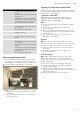
Customer service en 4Customer service Accessories When calling us, please give the product number (E no.) and the production number (FD no.) so that we can provide you with the correct advice. The rating plate with these numbers can be found inside the appliance (remove the metal mesh grease filter to gain access). You can make a note of the numbers of your appliance and the telephone number of the after-sales service in the space below to save time should it be required.
Installation instructions en INSTALLATION INSTRUCTIONS Installation instructions I ns t al at i on i ns t r uc t i ons HOHFWUR JD] (Important safety information Read these instructions carefully. Only then will you be able to operate your appliance safely and correctly. Retain the instruction manual and installation instructions for future use or for subsequent owners. Check the appliance for damage after unpacking it. Do not connect the appliance if it has been damaged in transport.
Important safety information en : Warning – Risk of death! Risk of poisoning from flue gases that are drawn back in. The exhaust air must not be conveyed into a functioning smoke or exhaust gas flue or into a shaft which is used to ventilate installation rooms that contain heating appliances. If the exhaust air is to be conveyed into a non-functioning smoke or exhaust gas flue, you must obtain the consent of the heating engineer responsible.
en General information : Warning – Risk of electric shock! Components inside the appliance may have sharp edges. These may damage the connecting cable. Do not kink or pinch the connecting cable during installation. Risk of electric shock! ■ It must always be possible to disconnect the appliance from the electricity supply. The appliance must only be connected to a protective contact socket that has been correctly installed.
Installation Preparing the ceiling ■ ■ ■ ■ The ceiling must be flat, horizontal and have adequate load-bearing capacity. The depth of the bore holes must be the same length as the screws. The wall plugs must have a secure grip. The enclosed screws and wall plugs are suitable for solid brickwork. Suitable fasteners must be used for other structures (e.g. plasterboard, porous concrete, poroton bricks). The max. weight of the extractor hood is 50 kg.
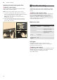
en Installation Fitting the lower support frame Fitting the appliance Fasten the upper and lower part of the support frame at the specified total height using 10 screws. 1. Hook the appliance from below into the support Notes ■ Ensure that the lower support frame is in the correct position. The open side must be facing the hob control elements. ■ The support frame can be subsequently re-positioned by loosening the securing screws. frame. Note: Ensure that the mains cable is not trapped. 2.
Installation Connecting the pipes Attaching the flue duct Note: If using an aluminium pipe, smooth the connection area beforehand. : Warning – Risk of injury! Exhaust-air pipe Ø 150 mm (recommended size) Attach the exhaust-air pipe directly to the air-pipe connector and seal. 1. Separate the flue ducts. Exhaust-air pipe Ø 120 mm 1. Attach the reducing connector directly to the air-pipe connector. 2. Attach the exhaust air pipe to the reducing connector. 3. Seal both joints appropriately.
6
6
Valid within Great Britain: Imported to Great Britain by BSH Home Appliances Ltd.