
Operation Manual


Product details | 25
6 720 815 257 (2014/10)MS 200
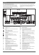
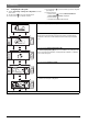
2.5 Scope of Delivery
Fig. 1, page 170:
[1] Module
[2] Cylinder temperature sensor (TS2)
[3] Collector temperature sensor (TS1)
[4] Bag with strain relief
[5] Installation instructions
2.6 Technical data
The design and operation of this product comply with
European Directives and the supplementary national
requirements. Its conformity is demonstrated by the CE
marking. You can ask for a copy of the declaration of conformity for this
product. For this see the contact address on the back cover of these
instructions.
2.7 Additional accessories
For precise information regarding suitable accessories, refer to your
local Bosch sales manager.
• For solar thermal system 1:
– Solar pump; connection to PS1
– Electronically controlled pump (PWM or 0-10 V); connection to
PS1 and OS1
– Temperature sensor (1st collector array); connection to TS1
(included in delivery)
– Temperature sensor at the bottom of cylinder 1; connection to
TS2 (included in delivery)
• Additionally for central heating backup (A) ( ):
– 3-way valve; connection to VS1/PS2/PS3
–
Temperature sensor at the middle of cylinder 1; connection to TS3
– Temperature sensor on the return; connection to TS4
• Additionally for cylinder 2/swimming pool with valve (B):
– 3-way valve; connection to VS2
–
Temperature sensor at the bottom of cylinder 2; connection to TS5
• Additionally for cylinder 2/swimming pool with pump (C):
– Solar pump 2; connection to PS4
–T
emperature sensor at the bottom of cylinder 2; connection to TS5
– 2nd electronically controlled pump (PWM or 0-10 V); connection
to OS2
• Additionally for central heating backup, cyl. 2 (D) ( ):
– 3-way valve; connection to VS1/PS2/PS3
–
Temperature sensor at the middle of cylinder 2; connection to TS3
– Temperature sensor on the return; connection to TS4
• Additionally for external heat exchanger at cylinder 1 or 2 (E, F or Q):
– Heat exchanger pump; connection to PS5
– Temperature sensor on heat exchanger; connection to TS6
• Additionally for 2nd collector array (G):
– solar pump 2; connection to PS4
– Temperature sensor (2nd collector array); connection to TS7
– 2nd electronically controlled pump (PWM or 0-10 V); connection
to OS2
• Additionally for return temperature control (H) ( ):
– Mixer; connection to VS1/PS2/PS3
–
Temperature sensor at the middle of cylinder 1; connection to TS3
– Temperature sensor on the return; connection to TS4
– Temperature sensor at the cylinder flow (downstream of mixer);
connection to TS8
• Additionally for transfer system (I):
– Cylinder transfer pump; connection to PS5
• Additionally for transfer system with heat exchanger (J):
– Cylinder transfer pump; connection to PS4
– Temperature sensor at the top of cylinder 1; connection to TS7
–
Temperature sensor at the bottom of cylinder 2; connection to TS8
– Temperature sensor at the top of cylinder 3; connection to TS6
(only if no heat appliance other than the solar system is installed)
• Additionally for thermal disinfection (K):
– Thermal disinfection pump; connection to PS5
Technical data
Dimensions (W×H×D) 246×184×61mm (further dimensions
Fig. 2, page 170)
Maximum conductor cross-
section
• 230 V terminal
• Extra-low voltage terminal
•2.5mm
2
•1.5mm
2
Rated voltages
•BUS
• Module mains voltage
•User interface
• Pumps and mixers
• 15 V DC (reverse-polarity-protected)
• 230 V AC, 50 Hz
• 15 V DC (reverse-polarity-protected)
• 230 V AC, 50 Hz
Circuit breaker 230 V, 5 AT
BUS interface EMS 2/EMS plus
Power consumption on –
standby
<1W
Max. output
Max. output per connection
• PS1; PS4; PS5; VS1/PS2/PS3
•VS2
1100W
• 400 W (high-efficiency pumps
permissible; max. 40 A/s)
•10W
Cylinder temperature sensor
measuring range
• Lower fault limit
• Display range
• Upper fault limit
• < – 10 °C
• 0 ... 100 °C
•>125°C
Capturing range, collector
temperature sensor
• Lower fault limit
• Display range
• Upper fault limit
• < – 35 °C
• – 30 ... 200 °C
•>230°C
Permitted ambient temp. 0 ... 60 °C
IP rating IP44
IP rating I
ID no. Data plate ( Fig. 19, page 173)
Table 7
°C °C °C °C
20 14772 45 5523 70 2332 95 1093
25 12000 50 4608 75 1990 100 950
30 9786 55 3856 80 1704 – –
35 8047 60 3243 85 1464 – –
40 6653 65 2744 90 1262 – –
Table 8 Temperature sensor measurements (TS2 - TS6, TS8 - TS16)
°C °C °C °C
– 30 364900 25 20000 80 2492 150 364
– 20 198400 30 16090 90 1816 160 290
– 10 112400 35 12800 95 1500 170 233
0 66050 40 10610 100 1344 180 189
5 50000 50 7166 110 1009 190 155
10 40030 60 4943 120 768 200 127
15 32000 70 3478 130 592 - -
20 25030 75 2900 140 461 - -
Table 9 Measuring values, collector temperature sensor (TS1 / TS7)