
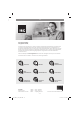
assembly Instructions

GB
- 14 -
machine is used in commercial, trade or industrial
businesses or for equivalent purposes.
4. Technical data
Mains connection ...................220-240 V ~ 50 Hz
Power consumption ................................ 1050 W
Max. pumping rate ..................................4500 l/h
Delivery head max. ..................................... 48 m
Delivery pressure max. ...........0.48 MPa (4.8 bar)
Suction height max. ....................................... 8 m
Pressure connection ..... approx. 33.3 mm (R1IG)
Suction connection ... approx. 42 mm (R1 ¼ AG)
Water temperature max. ............................. 35°C
Sound power level ............................ 84.8 dB (A)
Uncertainty ..............................................3.19 dB
Protection type .............................................IPX4
5. Before starting the equipment
Before you connect the equipment to the mains
supply make sure that the data on the rating plate
are identical to the mains data.
As a basic principle, we recommend the use of
a preliminary fi lter and a suction set with suction
hose, suction strainer and non-return valve, in
order to prevent long priming periods and unne-
cessary damage to the pump as a result of stones
and solid foreign bodies.
5.1 Connecting the intake line
•
Fasten the suction hose (at least approx. 19
mm (¾“) plastic hose with spiral reinforce-
ment) to the suction connection (approx. 42
mm / R1¼ male thread) of the equipment eit-
her directly or via a threaded nipple.
•
Use the connection adapter (8) to reduce the
thread of the suction connection to approx.
33.3 mm (R1 male thread).
•
The suction hose used should be equipped
with an intake valve. If the intake valve cannot
be used, a non-return valve should be ins-
talled in the intake line.
•
Position the intake line so that it rises from
the water withdrawal point to the equipment.
Avoid positioning the suction pipe higher than
the pump, as this would delay the escape of
air bubbles from the suction pipe and impede
the priming process.
•
Install the intake and discharge lines in such
a way that they do not exert any mechanical
pressure on the equipment.
•
The intake valve should be low enough in the
water to ensure that if the water level falls, the
equipment will not run dry.
•
A leaking intake line will draw in air and there-
fore not draw in any water.
•
Prevent the intake of foreign bodies (sand
etc.). If necessary, install a coarse filter for
this purpose.
5.2 Connecting the discharge line
•
The discharge line approx. 19 mm (¾ ”) must
be connected to the approx. 33,3 (R 1IG)
discharge line connector of the equipment
either directly or with the aid of a threaded
nipple.
•
With the right couplings it is also possible, of
course, to use a approx. 13 mm (½ “) delivery
hose. The smaller delivery hose results in a
lower delivery rate.
•
During the priming operation, fully open any
shut-off mechanisms (spray nozzles, valves,
etc.) in the pressure line so that the air can
escape without obstruction.
5.3 Electrical connections
•
Connect the appliance to a 220-240 V ~ 50
Hz socket-outlet with earthing contact. Mini-
mum fuse 10 ampere.
•
A built-in thermostat protects the motor from
overloading and blocking. The pump is swit-
ched off automatically by the thermostat if
overheating occurs and is switched on again
automatically after cooling.
6. Operation
•
Install the equipment on a solid and level
surface.
•
Fill the pump housing with water via the water
filler screw (3). Filling the intake line will acce-
lerate the priming process.
•
All the shut-off devices in the discharge line
(spray nozzle, valves etc.) must be fully ope-
ned during intake in order to permit all air to
escape from the intake line.
•
Connect the mains cable.
•
Switch on the equipment with the power
switch – priming can take up to 5 minutes at
maximum suction height.
•
After finishing the work, switch off the equip-
ment with the power switch.
Anl_NGP-E_105_SPK7.indb 14Anl_NGP-E_105_SPK7.indb 14 13.09.2021 08:18:3913.09.2021 08:18:39