
Installation Manual


Wiring Diagrams: Conventional Heating/Cooling Systems
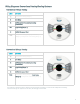
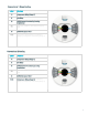
Conventional 1 Stage Heating
Label:
Function:
Y1
Compressor Relay (Stage 1)
G
Fan Relay
R
24VAC power from heating/cooling
transformer
W1
Heat Relay (Stage 1), Aux heat, Emergency
heat
C
24VAC Common Wire †
*/OB
Compressor Relay (Stage 2), Heat Relay
(Stage 2), Changeover Valve Relay (Stage 1)
Conventional 2 Stage Heating
Label:
Function:
Y1
Compressor Relay (Stage 1)
G
Fan Relay
R
24VAC power from heating/cooling
transformer
W1
Heat Relay (Stage 1), Aux heat, Emergency
heat
C
24VAC Common Wire †
*/OB
Compressor Relay (Stage 2), Heat Relay
(Stage 2), Changeover Valve Relay (Stage 1)
* Fan relay (G) is optional. However, without a G wire, Nest will not be able to control the fan independent of heating.
† Common wire (C) not required in most cases, but strongly recommended.
8