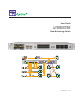
User Guide Data Monitoring Switch A 2 B A B 1 www.netoptics.com IDS Analyzer 1 Analyzer 2 Forensic RMON 1 RMON 2 Doc. PUBDIRU Rev.
PLEASE READ THESE LEGAL NOTICES CAREFULLY. By using a Net Optics Director device you agree to the terms and conditions of usage set forth by Net Optics, Inc. No licenses, express or implied, are granted with respect to any of the technology described in this manual. Net Optics retains all intellectual property rights associated with the technology described in this manual. This manual is intended to assist with installing Net Optics products into your network.
Director Contents Chapter 1 Introduction Key Features. . . . . . . . . . . . . . . . . . . . . . . . . . . . . . . . . . . . . . . . . . . . . . . . . . . . . . . . . . . . . . . . . . . . . . . . . . . . . 2 About this Guide. . . . . . . . . . . . . . . . . . . . . . . . . . . . . . . . . . . . . . . . . . . . . . . . . . . . . . . . . . . . . . . . . . . . . . . . . . 3 Director Architecture . . . . . . . . . . . . . . . . . . . . . . . . . . . . . . . . . . . . . . . . . . . . . . . . . . . . . . . . .
Director Chapter 3 Configuring Filters Using the CLI Syntax. . . . . . . . . . . . . . . . . . . . . . . . . . . . . . . . . . . . . . . . . . . . . . . . . . . . . . . . . . . . . . . . . . . . . . . . . . . . . . . . . 25 Copy Traffic From Any Network Port to Any Monitor Port. . . . . . . . . . . . . . . . . . . . . . . . . . . . . . . . . . . . . . . . 26 Aggregate Traffic From Any Set of Network Ports to Any Monitor Port. . . . . . . . . . . . . . . . . . . . . . . . . . . . . .
Director Chapter 1 Introduction Net Optics Director is a key component for building a comprehensive, consolidated monitoring infrastructure for both network management and security. It extends the range of visibility for data monitoring across converged data and digital voice networks, while eliminating monitoring port contention and minimizing the number of tools needed to optimally manage the network.
Director Key Features Ease of Use • • • • • • • • • • Tap, aggregation, regeneration, matrix switch, and filter functions in a single device 19-inch rack frame, 1U high Front-mounted connectors for quick and easy installation LED indicators show Power, Link, and Activity status Modular design for configuration flexibility RMON statistics, including network utilization filtering; data can be used to assemble XML-based end-user reports, or it may be exported to a third party reporting tool such as a protoco
Director About this Guide Please read this entire guide before installing Director. This guide applies to the following part numbers: Chassis Part Number Description DIR-3400 Director Main Chassis with 10 SFP monitor ports DIR-7400 Director Main Chassis with 10 SFP monitor ports, 2 XFP 10GbE ports, 2 XFP uplink ports DNM Part Number Description DNM-100 6-Port 10/100/1000 Copper In-Line Module DNM-110 12-Port 10/100/1000 Copper Span Module DNM-200 6-Port Gigabit SX Fiber 62.
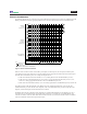
Director Director Architecture The following diagram shows a schematic view of the architecture of the Director device shown as a Matrix Switch with filtering. The black dots indicate aggregating Matrix Switch connections between Network Ports and Monitor Ports. DNM with 6 in-line network ports n1.1 n1.2 n1.3 n1.4 n1.5 n1.6 n1.7 n1.7 n1.9 n1.10 n1.11 n1.12 n2.1 n2.2 n2.3 n2.4 DNM with 12 Span or out-of-band network ports n2.5 n2.6 n2.7 n2.8 n2.9 n2.10 n2.11 n2.12 t1.
Director The inputs are divided into three groups: two DNMs plus the 10GbE ports. In-line DNM models support 6 in-line links, while Span DNM models support 12 Span ports. The diagram shows one in-line and one Span DNM. Both in‑line and Span DNMs are available with either Copper or SX, LX, or ZX Fiber interfaces. Different DNM types can be mixed in the same chassis, for example, one in-line Copper DNM and one Span Fiber DNM. The modules are hot-pluggable for easy serviceability.
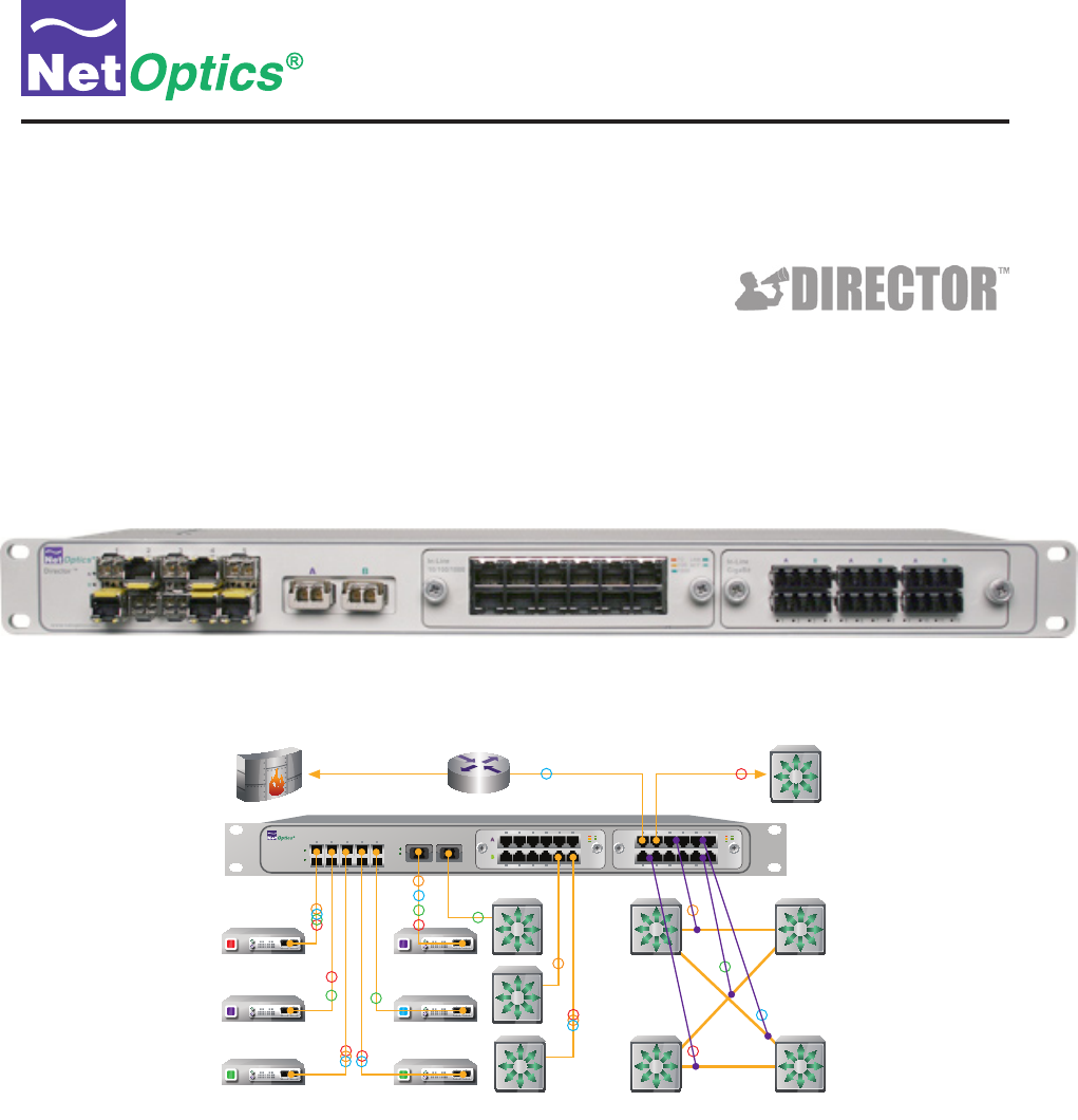
Director Typical Application The following diagram shows a typical application using Director to implement a comprehensive, consolidated monitoring infrastructure. A 2 B A B 1 www.netoptics.com IDS Analyzer 1 Analyzer 2 Forensic RMON 1 RMON 2 Figure 2: Director-centric network monitoring infrastructure In this example, eight network links are monitored by six monitoring devices. The company's external access is protected by a firewall, shown in the upper left of the diagram.
Director In this installation, Director has ten additional Span ports and one in-line link that are available for expansion, when more links need to be monitored. Monitoring Tools Still referring to Figure 2, six monitoring tools are connected to Director. They include protocol and performance analyzers, RMON probes, and an intrusion detection system (IDS).
Director In-line Monitoring of 10 Gigabit Links To create an in-line link on a 10 Gigabit network segment, use an external network Tap. Figure 4 shows an LC Fiber Tap being used to send two half-duplex data streams to two 10-Gigabit Director ports. This configuration creates a fully passive, secure in-line Tap for the 10 Gigabit network link. It is capable of transferring up to 20 Gbps of total traffic from the full-duplex link to Director.
Director Director Front Panel The features of the Director front panel are shown in the following diagram. 10 SFP Monitor Ports 1 Director ™ 2 3 4 2 XFP Configurable 10GbE Ports DNM with 10/100/1000 Copper Network Ports (6 In-line or 12 Span Ports) DNM with SX Fiber Network Ports (6 In-line or 12 Span Ports) 5 A 2 B In-Line 10/100/1000 10 LINK 100 ACT 1000 In-Line GigaBit A B A B A B A 1 www.netoptics.
Director Director Rear Panel The features of the Director rear panel are shown in the following diagram.
Director Chapter 2 Installing Director This chapter describes how to install and connect Director devices. The procedure for installing Director follows these basic steps: 1. Plan the installation 2. Unpack and inspect the Director device 3. Install the DNM modules 4. Install the SFP and XFP modules 5. Rack mount the Director device 6. Connect power to Director 7. Connect the command line interface (CLI) RS-232 DB9 port or the Management port 8. Log into the CLI 9.
Director Plan the Installation Before you begin the installation of your Director device, determine the following: • • • • • IP address of the Director device, or a range of IP addresses if you are deploying multiple Director devices Net Mask for Director IP address of the remote management console, if deployed over a WAN; this address is used for SNMP traps Gateway to the remote management console, if deployed over a WAN Port assignments and filters for the Network and Monitor port connections Make sure
Director Install Director Network Modules If the Director Network Modules (DNMs) are not already installed when you receive the unit, install them by sliding them into the DNM slots in the front panel. (If there is a plate covering the DNM slot, remove it by unscrewing two thumb‑screws, and then install the DNM module.) The DNM circuit boards ride in the rails provided in the slots. Push in the DNM firmly until you feel the connectors mate and the bezel is flush with the front panel, but do not force them.
Director Connect Power to Director For power fault protection, Director is equipped with redundant power connections. If one power source becomes unavailable due to an interruption in AC power or failure of the power brick, the other power source keeps Director operating normally. If both power sources become unavailable, Director passively keeps all in-line network links open, passing all traffic between the network ports. (When power is not available, no data is seen at the Monitor ports.
Director 2. Launch terminal emulation software and set communication parameters to: 115200 baud 8 data bits No parity 1 stop bit No flow control The Net Optics CLI banner and login prompt are displayed in the Terminal Emulation software. ********************************************************** * Net Optics Command Line Interface (CLI) * * * * Copyright (c) 2008 by Net Optics, Inc.
Director 3. Enter customer to log into the shell. The shell asks for the password. login as: customer customer@10.60.4.180's password: Figure 13: Shell login 4. Enter netoptics as the password. For security, the password is not displayed as you type it. The Director CLI runs and the CLI sign-on banner and login prompt are displayed. login as: customer customer@10.60.4.8's password: Last login: Thu Sep 4 09:40:31 2008 from 10.30.1.
Director Configure Director using the CLI You should be logged into the Director CLI. The factory-set default values for Director are: • Username: admin • Password: netoptics • • • • • IP Address: 10.60.4.180 (address for remote CLI, and for Indigo manager software, when available) Netmask: 255.0.0.0 (associated with IP Address) Manager IP Address: 192.168.1.2 (address for SNMP traps) Gateway IP Address: 10.0.0.
Director Assign a New Director IP Address, Netmask, and Gateway IP Address If you are using the local RS-232 serial interface to access the CLI, then you need to configure the IP Address that Indigo management software, when available, will use to communicate with Director. If Director must communicate through a Gateway to reach the network, then set the Gateway IP Address for that Gateway.
Director Set the Current Date and Time Director maintains a time-of-day clock which is used to record the time of traffic peak utilization events. Time is based on the 24-hour clock. The clock must be initialized using the CLI or another management tool. To change the current date and time: 1. Enter time hh:mm:ss where hh is hour, mm is minutes, and ss is seconds. 2. Enter date mm/dd/yyyy where mm is month, dd is day of the month, and yyyy is year.
Director Using the CLI Help Command To view CLI help information: 1. Enter Help at the "Net Optics:" prompt. The list of help topics is displayed.
Director Using the CLI Command History Buffer You can save a lot of typing by using the command history buffer maintained by the CLI. The up- and down-arrow keys scroll forward and backward through the history buffer. To execute a command again, simply scroll to that command and press enter. Alternately, you can scroll to a command and then edit it in-line before executing it. You can see a history of all the buffered commands by entering the history command.
1 6 Director Connect Span Ports to Director To connect Director to the network using Span ports, be sure that at least one of your DNMs is a Span model. Use ports in that DNM to connect to the network. Span port numbering is shown in the following diagram. It is the same for Span DNMs and in-line DNMs. Port # n1.1 2 3 4 A 7 8 9 .2 .3 .4 .5 .6 Port # n2.1 .2 .3 .4 .5 .6 5 Span 10/100/1000 B 10 LINK 100 ACT 1000 Span GigaBit 1 10 Port # n1.7 .8 .9 .10 .11 .
1 6 Director Connect Director With In-line Network Links To connect Director to the network using an in-line installation, be sure that at least one of your DNMs is an in-line model. Tap port-pairs for each link are located side by side, with three links across the top row and three links across the bottom row. This is true for both Fiber and 10/100/1000 DNMs. Link # 1 Port # n1.1 2 3 4 8 9 .3 3 .4 .5 Link # 7 8 Port # n2.1 .2 .6 9 .3 .4 .5 A B A .6 5 A 7 2 .
Director 1 Director ™ 2 3 4 5 A 2 www.netoptics.com B In-Line 10/100/1000 10 LINK 100 ACT 1000 In-Line GigaBit A B A B A B A B 1 6 7 8 9 1 10 2 3 4 5 6 7 8 9 10 11 12 Figure 21: In-line Network connections Connect Monitoring Tools to Director To connect a monitoring tool to Director, simply plug the appropriate cable into the desired 1 Gigabit or 10 Gigabit Monitor port and plug the other end into the monitoring tool.
Director Chapter 3 Configuring Filters Using the CLI This chapter describes how to use the CLI to determine which monitoring tools are connected to which Network ports. It also explains how to create filters to limit the amount of traffic copied to Monitor ports, so the monitoring tools receive only the traffic that is of interest to them.
Director Copy Traffic From Any Network Port to Any Monitor Port Director can be used like a Matrix Switch to direct traffic from any Network port to any Monitor port. To create a simple switch connection, use a filter add command without specifying any filters. The filter add command creates pending filters (including switch settings); they are not activated until a filter commit command is executed. Any number of filter add commands may be issued prior to executing the filter commit command.
Director Network Port 1 + Monitor Port 3 Network Port 2 filter add in_ports=n1.1,n1.2 action=redir redir_ports=m.3 Figure 23: Traffic aggregation Regenerate Traffic to Any Set of Monitor Ports Director can be used like a Regeneration Tap, copying traffic from a Network port (or aggregated group of Network ports) to multiple Monitor ports. The filter add command is used to do this.
Director Create Filters Filters process a traffic stream by selecting packets based on criteria in the packet header. A filter is defined using a filter add command, which also specifies the Network ports and Monitor ports the filters apply to.
Director • • • • • • • • • ip_src, ip_src_mask ip_dst, ip_dst_mask ip6_src, ip6_src_mask ip6_dst, ip6_dst_mask l4_src_port, l4_src_port_mask l4_dst_port, l4_dst_port_mask mac_src, mac_src_mask mac_dst, mac_dst_mask vlan IPv4 source address and mask IPv4 destination address and mask IPv6 source address and mask IPv6 destination address and mask Layer 4 source port and mask Layer 4 destination port and mask MAC source address and mask MAC destination address and mask VLAN number Create Complex Filters Mult
Director Protocol = TCP Network Port 5 + Monitor Port 1 Protocol = UDP filter add in_ports=n1.5 ip_proto=6 action=redir redir_ports=m.1 filter add in_ports=n1.5 ip_proto=17 action=redir redir_ports=m.1 Figure 29: Logical OR filter connection View filters To view a list of all pending filters, enter filter list. To view the active filters, enter filter running. Net Optics> filter list Filter #1 src_mac=00:00:00:00:00:00 dst_mac=00:00:00:00:00:00 src_ip=0.0.0.0/255.255.255.255,dst_ip=0.0.0.0/255.255.
Director Work with configurable 10 Gigabit ports The two configurable 10 Gigabit XFP ports on the front panel are designated t1.1 (on the left) and t1.2 (on the right), and the two on the rear panel are t2.1 (on the left) and t2.2 (on the right). They can be used in Network port lists and Monitor port lists. The 10 Gigabit ports are configured for Network or Monitor as required by the filter add commands you enter. Some examples follow.
Director Network Port 1 Network Port 2 Network Port 3 + XFP Port 1.1 Network Port 4 Network Port 11 XFP Port 1.2 filter add in_ports=n1.1-n1.4 action=redir redir_ports=t1.1 filter add in_ports=n1.11 action=redir redir_ports=t1.2 Figure 32: Configurable 10 Gigabit XFP ports used as Monitor ports (with aggregation) To use one XFP port as a Span port and the other XFP port as a Monitor port: 1. Enter filter add in_ports=t1.1 ip_proto=6 action=redir redir_ports=m.1.
Director Understand filter interactions It is important to understand that Director uses Content Addressable Memory (CAM) technology to implement filters. As each filter is defined, it is stored in the next available entry in the CAM. Each packet header is compared in the CAM, and the CAM returns the index of the first filter that the packet header matched. That filter, and only that filter, controls which monitoring ports receive a copy of the packet. Other filters are not executed for that packet.
Director Have we achieved our goal of sending all the TCP traffic to Monitor Port 2? Not quite. What happens when an TCP packet arrives from 192.186.10.0? It matches the filter at CAM address 1, so it is copied to Monitor Port 1. But that is all that happens; it does not go to Monitor Port 2. The flow is correctly shown in the following diagram. CAM Network Port 5 Source IP = 192.186.10.0 Address match Monitor Port 1 no match Protocol = TCP Filter 1 n1.5 ip_src=192.186.10.0 m.1 2 n1.
Director Note:___________________________________________________________________________________________________ Instead of filter add, you can use a filter ins command to define filters. The only difference is that filter ins allows you to specify the filter's ID, which is its position in the pending filter list. (Use filter list so see the IDs of all pending filters.) When you use a filter ins command, the first argument must be id= where is a decimal number in the range 1 to 999.
Director Understand pending and active filters To understand the actions of filter commands such as filter commit, filter discard, and filter delete, it is helpful to visualize the pending filter list and the CAM that holds the active filters. The previous section explained how the active filters are stored in a CAM, which can be thought of as list of active filters. These filters, which are actively running in the device, may be referred to as active, running, or committed.
Director 1. Enter filter running to view the currently active filters in the CAM. Net Optics> filter running Filter #1 src_mac=00:00:00:00:00:00 dst_mac=00:00:00:00:00:00 src_ip=0.0.0.0/255.255.255.255,dst_ip=0.0.0.0/255.255.255.255,ip_proto=0017 l4_src_port=0000,l4_dst_port=0000,vlan=0000,action=drop in_ports= Filter #2 src_mac=00:00:00:00:00:00 dst_mac=00:00:00:00:00:00 src_ip=0.0.0.0/255.255.255.255,dst_ip=0.0.0.0/255.255.255.
Director 4. Enter filter list to view the pending filter list. Net Optics> filter list Filter #1 src_mac=00:00:00:00:00:00 dst_mac=00:00:00:00:00:00 src_ip=0.0.0.0/255.255.255.255,dst_ip=0.0.0.0/255.255.255.255,ip_proto=0006 l4_src_port=0000,l4_dst_port=0000,vlan=0000,action=drop in_ports= Filter #2 src_mac=00:00:00:00:00:00 dst_mac=00:00:00:00:00:00 src_ip=0.0.0.0/255.255.255.255,dst_ip=0.0.0.0/255.255.255.255,ip_proto=0000 l4_src_port=0000,l4_dst_port=0000,vlan=0000,action=redir in_ports=n1.
Director Be aware of these similar pairs of commands: • filter discard clears the pending filter list, while filter clear clears the CAM • filter list shows the pending filter list, while filter running shows the CAM • filter commit copies the pending filter list to the CAM, while filter sync copies the CAM to the pending filter list CAM Pending filter list Address Filter 1 2 filter commit Address Filter 1 2 filter sync filter discard to clear filter list to view contents filter clear to clear fil
Director Chapter 4 Daisy-chaining Multiple Director Chassis This chapter describes how to expand the capacity of Director by daisy-chaining multiple Director chassis. The complete set of chassis becomes a single logical system with up to 380 total ports. By using long-reach ER links, chassis can be physically separated by as much as 25 miles (40 kilometers), enabling monitoring of entire campuses or multiple campuses with a single Director system.
Director Appendix A Director Specifications Specifications, chassis Mechanical Dimensions: 1.6” high x 15.
Director Specifications, DNM Copper Interface (12) RJ45 Network Ports 10/100/1000Mbps (6) In-line links or (12) Span ports depending on model 22-24 AWG unshielded twisted pair cable, CAT5e or better recommended Fiber Optic Interface (12) Gigabit SX, LX, or ZX Network Ports, LC type (6) In-line links or (12) Span ports depending on model Fiber Types: Corning Multimode 62.5/125μm Corning Multimode 50/125μm Corning Singlemode 8.5/125μm Transceiver: SX GigaBit 850nm, VCSEL, supports 62.
Director Appendix B Command Line Interface Tip!_ ___________________________________________________________________________________________________ The command line interface (CLI) is case-sensitive; commands must be entered in lower case. However, certain items such as user-defined text strings, user names, and passwords may be entered in upper, lower, or mixed case, and are case-sensitive also.
Director Command Sub-Command ! Arguments Example and description [#] (a number) !3 Executes a command from the CLI command history buffer (see history command) commit commit Activates pending changes previously defined using filter commands AND saves the changes as the new default configuration date date 06/24/2008 Arguments: is mm/dd/yyyy Sets the system calendar date; if is omitted, the current date is displayed del del my_configuration-1 Arguments:
Director Command Sub-Command Arguments Example and description filter commit (continued) del filter commit Activates pending filters previously defined using filter add and filter ins commands but does NOT save the changes as the new default configuration ipv6=y id= filter del id=3 Arguments: ipv6=y for IPv6 addressing; omit for IPv4 is a decimal number from 1 to 999 that identifies which filter is to be deleted Deletes a pending filter discard filter discard Clears all pending filters i
Director Command Sub-Command image Arguments Example and description <1|2> image 2 Arguments: Valid values are 1 and 2 Chooses which system image to boot from (see upgrade command) show image show Lists the names of both system images and indicates which one is running, and which one is selected to boot from (arrow next to image name) list list Shows a list of filenames of saved Director device configurations (see save command) load load my_configuration-1 Arguments: is t
Director Command Sub-Command Arguments Example and description quit quit Exits the CLI shell (same as exit and logout) Note: To maintain system security, control is not returned to the command shell.
Director Command Arguments Example and description time Sub-Command
Director Filter parameters Switches and filters are defined using the filter add and filter ins commands. The filter add command syntax is: filter ipv6=y add in_ports= action= redir_ports= The is a sequence of zero or more of the filter qualifiers as listed in the following table. If the is empty, the filter add command specifies an aggregation of the traffic received on all of the in_ports.
Director Director Filter Parameters Example Description ip_proto Number* ip_proto=6 Layer 4 IP protocol ip_src IPv4 address ip_src=168.10.4.1 IPv4 source address ip_src_mask IPv4 address mask ip_src_mask=255.255.255.0 Mask for IPv4 source address ip_dst ip_dst=168.10.4.2 IPv4 destination address ip_dst_mask IPv4 address mask ip_dst_mask=255.255.255.
Director Appendix C Protocol Numbers The official Assigned Internet Protocol Numbers list is maintained by the Internet Assigned Numbers Authority and can be found at http://www.iana.org/assignments/protocol-numbers. The list as of April 18, 2008 is reproduced in the following table (without references).
Director Num Keyword Protocol Num Keyword Protocol 55 MOBILE IP Mobility 85 NSFNET-IGP 56 TLSP Transport Layer Security Protocol using Kryptonet key management NSFNETIGP 86 DGP Dissimilar Gateway Protocol 87 TCF TCF 88 EIGRP EIGRP 89 OSPFIGP OSPFIGP 90 SpriteRPC Sprite RPC Protocol 91 LARP Locus Address Resolution Protocol 92 MTP Multicast Transport Protocol 57 SKIP SKIP 58 IPv6ICMP ICMP for IPv6 59 IPv6NoNxt No Next Header for IPv6 60 IPv6-Opts Destination Op
Director Num Keyword Protocol Num Keyword 115 L2TP Layer Two Tunneling Protocol 134 116 DDX D-II Data Exchange (DDX) 117 IATP Interactive Agent Transfer Protocol RSVPE2EIGNORE 135 Mobility Header 136 UDPLite 137 MPLSin-IP Protocol 118 STP Schedule Transfer Protocol 119 SRP SpectraLink Radio Protocol 120 UTI UTI 121 SMP Simple Message Protocol 138 manet MANET Protocols 122 SM SM 139 HIP Host Identity Protocol 123 PTP Performance Transparency Protocol 124 ISIS
Director Limitations on Warranty and Liability Net Optics offers a limited warranty for all its products. IN NO EVENT SHALL NET OPTICS, INC. BE LIABLE FOR ANY DAMAGES INCURRED BY THE USE OF THE PRODUCTS (INCLUDING BOTH HARDWARE AND SOFTWARE) DESCRIBED IN THIS MANUAL, OR BY ANY DEFECT OR INACCURACY IN THIS MANUAL ITSELF.
www.netoptics.com © 2008 by Net Optics, Inc. All Rights Reserved.