Installation Guide for Fiber Mode Converters Doc PUBFMCSAU Rev.
Fiber Mode Converter Contents Introduction. . . . . . . . . . . . . . . . . . . . . . . . . . . . . . . . . . . . . . . . . . . . . . . . . . . . . . 1 Key Features. . . . . . . . . . . . . . . . . . . . . . . . . . . . . . . . . . . . . . . . . . . . . . . . . . . . . 2 Product Features. . . . . . . . . . . . . . . . . . . . . . . . . . . . . . . . . . . . . . . .
Fiber Mode Converter PLEASE READ THESE LEGAL NOTICES CAREFULLY. By using a Net Optics Fiber Mode Converter you agree to the terms and conditions of usage set forth by Net Optics, Inc. No licenses, express or implied, are granted with respect to any of the technology described in this manual. Net Optics retains all intellectual property rights associated with the technology described in this manual. This manual is intended to assist application in installing Net Optics products into your network.
Fiber Mode Converter Introduction Net Optics Singlemode to Multimode Converters are simple and reliable devices for connecting multimode fiber traffic to single mode fiber devices and links. Use these bi-directional media converters individually to connect 100Base-FX multimode and singlemode devices, or in pairs at each end of long-distance singlemode fiber links.
Fiber Mode Converter Key Features Passive, Secure Technology • Net Optics’ Fast Ethernet FMC series converters are 100Base-FX to 100Base-FX converters. The units comply with all applicable IEEE 802.3u specifications. • The FMC series converters are designed to be simple plug-and-play products. Just plug the multimode or single mode fiber optic connectors into the appropriate port and the conversion is done.
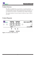
Fiber Mode Converter Product Features The FMC-SA and FMC-R have one pair (Port 1) of standard, multimode, 1300 nm fiber optic SC type connectors and a pair (Port 2) of fiber optic, 1310 nm singlemode SC connectors. The singlemode, fiber optic connectors are eye-safe Laser driven and have a transmission range of 15Km in full duplex. The standard multimode connectors support a transmission range of 2Km in full duplex. Product Diagrams Figure 1.
Fiber Mode Converter Connecting to the Network 1. Unpack the Fiber Mode Converter, verify that you have all components, and obtain the required cables needed to successfully install the unit. Your package should contain: one Converter, one power supply, one power cord and one users Manual (this manual). 2. Multimode Ports: Using a duplex SC multimode cable, connect the appropriate switch, server, or router to the Fiber Mode Converter's Multimode Port. 3.
Fiber Mode Converter Connecting to the Network The FMC series converters with F/O connections operate over duplex fiber optic cable. This means that two separate fiber optic cables are used for data transmission. One cable is for transmitting data and the other is for receiving data. The transmit port is designated with TX and the receive port is designated with RX.
Fiber Mode Converter Maximum Round Trip Delay There are certain rules of Fast Ethernet installation a user must understand in order to be able to calculate valid cable lengths in a given set up situation. Maximum round trip delay in bit times is 512; late collisions and/or CRC errors are indicators that the path delays exceed 512 bit times. For a network to be valid the worst-case path delay value (PDV) must be 512 bit times or less.
Fiber Mode Converter Examples Maximum of 512 total bit times between the two farthest DTEs DTE TX to DTE FX has 100 bit times delay CFT converter has a 50 bit time delay Class I repeater has 140 bit times delay TX cable has 1.112 bit times delay per meter F/O cable has 1.
Fiber Mode Converter Examples (continued) If cable A to B is 10 meters of STP and cable B to C is 150 meters of F/O, then what is the maximum length of the Cat 5 cable C to D? Total maximum bit time Less DTE TX to TX Less (2 x CFT converters) Less (10m x 1.112) Less (150m x 1.0) Remaining bit time +512 -100 -20 -11.12 -150 +230.88 Remaining bit time divided by 1.112 (the bit time delay per meter of Cat 5 cable) yields a maximum C to D cable of 207 meters.
Fiber Mode Converter Configuration Guidelines for Link Fault Signaling (LFS) Operation Link Fault Signaling (LFS) circuitry provides visual indication of link condition on both segments as well as alerting each host DTE when the remote link (segment) is down. 1. The FMC series converter operates when it receives a link signal from a device attached to either port 100Base-FX), then turns-on the link signal to the device on the other (port) segment.
Fiber Mode Converter Safety Notes on Laser Singlemode type Connectors The FMC-SA uses 1300 nm wavelength, eye-safe type laser, fiber optic single mode connectors. When connecting pairs of devices using laser type connectors or connecting pairs of devices using LED type connectors, simply plug in the fiber optic connectors in the normal manner.
Fiber Mode Converter Specifications Environmental Operating Temperature: 0˚C to 40˚C Storage Temperature: -10˚C to 70˚C Relative Humidity: 5% min, 95% max, non-condensing Power Power Supply Input: 100-240 VAC, 0.6A, 50-60 Hz (AC100-125V~30VA, 50-60 Hz, for Japan) Output: 5V, 2A (5V, 2.4A for UK and Japan) Mechanical Dimensions: 1.0” high x 5.3” deep x 2.
Fiber Mode Converter Port #1 Connector: Two SC type (multimode) Optical transmitter: Wavelength: 1300 nm Link length: 412m half duplex max, 2km full duplex max Output power (multi mode): 19 dBm min, 14 dBm max (62.5/125 fiber) Optical receiver input sensitivity (multi mode): 33.5 dBm typ, 31dBm max Certifications • The Net Optics’ converters are designed to comply with all the following safety, emissions and susceptibility specifications: UL 1950, CSA-C22.2 No.
Fiber Mode Converter Limitations on Warranty and Liability Net Optics offers a limited warranty for all its products. IN NO EVENT SHALL NET OPTICS, INC. BE LIABLE FOR ANY DAMAGES INCURRED BY THE USE OF THE PRODUCTS (INCLUDING BOTH HARDWARE AND SOFTWARE) DESCRIBED IN THIS MANUAL, OR BY ANY DEFECT OR INACCURACY IN THIS MANUAL ITSELF.
Fiber Mode Converter Notes: 14
www.netoptics.com © 2010 by Net Optics, Inc. All Rights Reserved.