
Manual


GigaBit Fiber In-Line Regeneration Taps
4
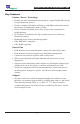
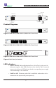
Product Diagrams
Figure 1: RGN-SX-IL2, RGN-50SX-IL2, RGN-LX-IL2 Front Panel
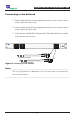
Figure 2: RGN-SX-IL4, RGN-50SX-IL4, RGN-LX-IL4 Front Panel
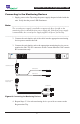
Figure 3: RGN-SX-IL8, RGN-50SX-IL8, RGN-LX-IL8 Front Panel
Figure 4: Back Panel (all models)
LED Indicators
•. PWR 1/ PWR 2:.Main.and.Redundant.Power.If.the.Tap.is.deployed.with.
both.power.supplies,.both.LEDs.illuminate.white.when.the.Tap.is.connected.
to.power.An.off.power.LED.indicates.that.the.corresponding.power.supply.
is.not.functioning.or.not.connected.
• Link Port A/B:.. Illuminates.when.link.is.established.with.another..device..
connected.to.the.A.port.and.B.port.respectively
Regeneration Tap™
www.netoptics.com
B
A
Monitor
Network
LASER
CAUTION!
LINK
1
2
B
A
1 2 A B
SC Duplex Interface
(angled) x2
SC Duplex Interface
(angled) x2
Monitor Ports
Network Ports
Link Status
LED's
Power LEDs
Regeneration Tap™
www.netoptics.com
B
A
Monitor
Network
LASER
CAUTION!
LINK
1
2
B
A
1 2 A B3 4
Regeneration Tap™
www.netoptics.com
B
A
Monitor
Network
LASER
CAUTION!
LINK
1
2
B
A
1 2 A B3 4 5 6 7 8