Installation Guide IFWA-661 - Outdoor Wireless Antenna
Important Notice This device, like any wireless device, operates using radio signals which cannot guarantee the transmission and reception of data in all conditions. While the delay or loss of signal is rare, you should not rely solely on any wireless device for emergency communications or otherwise use the device in situations where the interruption of data connectivity could lead to death, personal injury, property damage, data loss, or other loss.
Document history This document covers the following product: NetComm Wireless IFWA-661 Outdoor Wireless Antenna VER. v1.0 DOCUMENT DESCRIPTION Initial document release DATE September 20, 2019 Table i. - Document revision history IFWA-661 Outdoor Wireless Antenna – Installation Guide v1.
Contents Overview .............................................................................................................................................................................. 6 Introduction .............................................................................................................................................................................................................. 6 Target audience ...............................................................................
Product Warranty ................................................................................................................................................................ 63 IFWA-661 Outdoor Wireless Antenna – Installation Guide v1.
Overview Introduction This document provides you with an overview of the installation process for the IFWA-661 Outdoor Wireless Antenna. Target audience This document is intended for system integrators or experienced hardware installers who understand telecommunications terminology and concepts.
Product introduction Product overview Rural and regional homes and businesses, remote commercial sites and metropolitan fringe districts located beyond the reach of fixed line infrastructure rely on mobile networks to access broadband Internet.
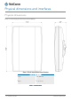
Physical dimensions and interfaces Physical dimensions Below is a list of the physical dimensions of the IFWA-661. Figure 1 – IFWA-661 Outdoor Wireless Antenna Dimensions IFWA-661 DIMENSIONS Length 17.5” (445 mm) Width 11.3” (287 mm) Height 4.5” (113 mm) Weight ~5.7lbs (~2.59 kg) Table 1 - Device Dimensions IFWA-661 Outdoor Wireless Antenna – Installation Guide v1.
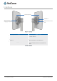
Interfaces Antenna panel SIM hatch Antenna Power Supply port (PoE) Smart Antenna Tool port Figure 2 – Interfaces ITEM DESCRIPTION Antenna panel Includes 2 x pairs Cross polarised antennas and GPS antenna Smart Antenna Tool port Connect the Smart Antenna Tool here SIM hatch Open the hatch to insert SIM here Antenna Power Supply port (PoE) Provides power and data connectivity to the Outdoor Wireless Antenna with Ethernet cable Table 2 – Interfaces IFWA-661 Outdoor Wireless Antenna – Installation
Installation considerations As the Outdoor Wireless Antenna is aligned specifically for a property, please take note of the following when installing the equipment: After alignment, do not move, place anything in front of, or adjust the position of the Outdoor Wireless Antenna since this will likely have a negative impact on the signal quality and performance of the wireless service. Keep trees and branches away from the Outdoor Wireless Antenna.
Installing the Outdoor Wireless Antenna The image below illustrates a typical installation of the Outdoor Wireless Antenna. Figure 3 - Typical Outdoor Wireless Antenna Installation Determining the best location for the Outdoor Wireless Antenna Determining the best location for the Outdoor Wireless Antenna involves: 1 Performing a survey of the site using the Smart Antenna Tool.
Assemble and attach the mounting bracket Notes on mounting: Use a standard 13mm socket wrench for all bolts Tighten bolts to the following torque settings: Captive radome mount bolts: 35 in-lbs Angle pivot bolt: 65 in-lbs Pipe clamp bolt: 80 in-lbs Do not over tighten bolts Radome mount Pipe clamp Pipe clamp bolt Angle pivot bolt Captive radome mount bolt Figure 4 - IFWA-661 mounting bracket and bolts IFWA-661 Outdoor Wireless Antenna – Installation Guide v1.
Mounting bracket assembly 1 Attach the pipe clamp to the radome mount using the angle pivot bolt, nut and washer. Pipe clamp Pipe clamp bolt Captive radome mount bolt Angle pivot bolt Radome mount Angle pivot Angle pivot bolt nut bolt washer Figure 5 - Mounting bracket assembly 2 Attach the assembled mounting bracket to the antenna as shown below. Tighten the captive radome mount bolts to the torque settings described here.
Connect the Smart Antenna Tool to the Outdoor Wireless Antenna 1 Turn the plug on the console port hatch counter-clockwise so that it is in the unlocked (vertical) position as shown in the image below. Figure 7 - Unlocking the console port hatch 2 Pull the plug out to reveal the console port. Figure 8 - Console port IFWA-661 Outdoor Wireless Antenna – Installation Guide v1.
3 Remove the cap from the head of the Smart Antenna Tool and insert it into the console port as shown in the picture below. Figure 9 - Attached Smart Antenna Tool Perform the site survey Push the power button on the Smart Antenna Tool to turn it on. After a few seconds, the LEDs illuminate. On each start up, the Smart Antenna Tool LEDs flash both red and green twice a second, indicating that the compass requires calibrating.
When the Smart Antenna Tool is connected to the OWA, it enters Cell scanning mode. During cell scanning mode, the LED indicators display as below, depending on the status. Figure 10 - Smart Antenna Tool LED statuses in cell scanning mode Connect your wireless device (e.g. laptop/tablet/smartphone) to the SSID of the alignment tool. In a web browser, go to http://192.168.3.1 and use the alignment tool to estimate the best position for the Outdoor Wireless Antenna while you are on the ground.
Place the Outdoor Wireless Antenna on the pole 1 Assemble the Pipe Bracket to pole, pointing bracket in desired antenna direction. Secure the pipe clamp bolts Figure 11 - Assembling pipe bracket to pole 2 Alternately tighten the top and bottom pipe clamp bolts to maintain even pressure on the pipe, to 80 in-lb. Figure 12 - Tightening pipe clamp bolts IFWA-661 Outdoor Wireless Antenna – Installation Guide v1.
Assemble the Outdoor Wireless Antenna Power supply weather seal The Outdoor Wireless Antenna Power supply weather seal must be properly attached to prevent dust and water from entering the Outdoor Wireless Antenna’s housing. To connect Ethernet cable via the Power supply weather seal: 1 Unscrew the weather cap and remove the rubber gasket. 2 Separate the rubber seal and the ferrule.
5 Place the ferrule over the Ethernet cable as shown, making sure that the “teeth” are facing the nut. Figure 16 - Ferrule placed over Ethernet cable 6 Place the rubber seal over the Ethernet cable with the wide end toward the RJ45 plug. See the image below for the correct orientation. Figure 17 - Rubber seal placed over Ethernet cable 7 Push the ferrule over the rubber seal to prevent it from coming apart.
8 Place the washer seal over the Ethernet cable as shown below. Ensure that the inside protruding lip is on the opposite side of the Ethernet plug. Figure 19 - Washer seal placed over Ethernet cable 9 Place the neck over the Ethernet cable as shown below. Figure 20 - Neck placed over Ethernet cable IFWA-661 Outdoor Wireless Antenna – Installation Guide v1.
10 Plug the Ethernet cable into the Ethernet port. Figure 21 - Plugging in the Ethernet cable 11 Put the neck into the opening and turn the neck clockwise until it locks in place. 12 Push the rubber seal and ferrule into the neck then screw the nut on to the neck. Figure 22 - Rubber seal and ferrule inserted into neck IFWA-661 Outdoor Wireless Antenna – Installation Guide v1.
13 Turn the nut clockwise to tighten it the washer seal against the housing. Continue turning the nut until completely assembled. This will allow the washer seal to grip the cable while also applying enough pressure to the washer seal to prevent dust and moisture entering the unit. Figure 23 - Turning the nut clockwise IFWA-661 Outdoor Wireless Antenna – Installation Guide v1.
Aligning the Outdoor Wireless Antenna Before proceeding with the installation of the IFWA-661, please ensure that the following steps have been taken: Perform an indoor site survey Capture the customer’s signature Scan the antenna barcode to activate the unit Connect the Smart Antenna Tool to the antenna and power it on Connect your wireless device for alignment to the Smart Antenna Tool’s wireless network Launch the wireless device’s browser and navigate to the antenna’s IP address Process flow (subject t
Process flow – User interface screens Successful Installation 1. Data Entry Screen IFWA-661 Outdoor Wireless Antenna – Installation Guide v1.
2. Network Scan Screen 3. CBRS Install Parameters Screen - If LTE limited service or SIM card error, error status is shown along with a guideline. IFWA-661 Outdoor Wireless Antenna – Installation Guide v1.
CBRS Install Parameters Screen - If no error in LTE service and SIM card: a) If CPI credential is provided in Quick Copy, installers are not asked to provide Key File and Pass-code b) If the given key file and passcode are valid and correct: Note: If CPI credential is not provided in Quick Copy, the page show input fields for installers can provide Key File and Passcode. IFWA-661 Outdoor Wireless Antenna – Installation Guide v1.
c) If either the given key file or passcode are invalid or incorrect, an indicator in red color is shown: The .P12 file is encrypted. The Install Tool will decrypt the package using the Passcode and extract the CPI Private Key when signing the CBRS Install Parameters. CBRS Install Parameters Screen (Successful Registration) - Installer can click on the button Register to trigger the CBRS Registration process. IFWA-661 Outdoor Wireless Antenna – Installation Guide v1.
4. Speed Test (Success) 5. Mount Installation (Installer installs supporting hardware for antenna mounting) IFWA-661 Outdoor Wireless Antenna – Installation Guide v1.
6. Data Entry Screen IFWA-661 Outdoor Wireless Antenna – Installation Guide v1.
7. Network Scan Screen IFWA-661 Outdoor Wireless Antenna – Installation Guide v1.
8. CBRS Install Screen (Successful Registration) 9. Speed Test (Success) IFWA-661 Outdoor Wireless Antenna – Installation Guide v1.
10. Finish Installation (QR Code Generation) IFWA-661 Outdoor Wireless Antenna – Installation Guide v1.
Site Survey with Failed Install Location 1. Data Entry Screen IFWA-661 Outdoor Wireless Antenna – Installation Guide v1.
2. Network Scan Screen 3. CBRS Install Screen (Successful Registration) IFWA-661 Outdoor Wireless Antenna – Installation Guide v1.
4. Speed Test (Fail) 5. Move to New Location (QR Code Generation) IFWA-661 Outdoor Wireless Antenna – Installation Guide v1.
Installation flow – Site survey To find the correct position and orientation at site to install the antenna. 1 Data Entry 2 Network Scan 3 Move to New Location (Capturing QR Code) 4 QR Code Screen 5 Move to New Location Installation flow - Post site survey After confirming the installation position on site, including manual mounting of antenna, the following steps finalize the installation process.
Figure 25 - Data entry screen IFWA-661 Outdoor Wireless Antenna – Installation Guide v1.
Note that until a selection is made using the Band Select drop down list, the antenna will not be scanning. Once the settings are applied, the device will start scanning on the targeted band and will connect. At the time of connection, any pending SIM OTA will occur. Note also that if the unit was previously powered on and had gone through this page, all previous data will still be populated, but no network connectivity will occur on this page in case any data changes.
To try a new location, continue to the Move to New Location section. To perform Advanced Operations, continue to the Advanced Operations section. CBRS Install Parameters CBRS screen shows for the installation parameters with two columns. The first column is what is current from the tool and the second is what can be used for Registration. Figure 27 - CBRS Install Parameters The first column is read-only and will continue to be updated throughout the Install procedure.
Latitude Longitude Height (Above Mean Sea Level – WGS84) Azimuth (with respect to True North, not magnetic north) Downtilt (when the antenna is mounted facing the horizon, the downtilt reading is zero. When it faces the ground, the reading is positive, otherwise it will display a negative reading.) The Copy button provides the option to copy Smart Antenna Tool data to Registration side. The copy operation will overwrite any data in the Registration column.
Speed Test The Speed Test screen shows a Status, Progress and Speed for both Download and Upload tests. Figure 28 - Speed Test (if unmounted) screen Figure 29 - Speed Test (if mounted) screen IFWA-661 Outdoor Wireless Antenna – Installation Guide v1.
Informational text fields for Serving Cell and Test start time are shown. The installer can run a speed test by clicking the Run Speed Test. When the Speed Test button is selected, the device will attempt three cycles of each download and upload, updating status, progress and throughput as the test progresses. If the installer wishes to go back to the previous screen, they make click “Back”. If the device is not mounted*, then the prompt is shown for “Mount Unit”.
Finish installation Figure 31 - Finish Installation The Finish Installation screen displays status fields for: CBRS Registration Status (Not Registered, Registering, Registered – Grant Pending, Registered – Grant Authorized) Serving cell Press and hold on the QR code below to save the image to your device. The filename of the saved file will contain the BAN and date. The screen displays “It is now safe to remove the Smart Antenna Tool”.
Advanced Operations Figure 33 - Advanced Operations screen IFWA-661 Outdoor Wireless Antenna – Installation Guide v1.
If there is an updated version of OA firmware and/or OA screens, there will be an Update OWA Firmware button; otherwise, the button will be grayed out. Not yet available and subject to change. Note that in some cases, new screens may require new APIs which would force an OA firmware update prior to a screen update being made available. If the installer selects the Update Firmware button, then flow is transferred to the OA Update Screen.
OWA Update To update OWA firmware without entering data into the Data Entry screen, 1 Navigate to http://192.168.3.1/advanced_operations.html. A list of firmware files that exist on the Smart Antenna Tool is displayed. 2 Next to the firmware version you want to install, click the “Upgrade” button. A screen displays the installation progress as the OWA firmware is upgraded.
Move to New Location Installer will be given the option to generate a QR Code. Status fields are provided for: CBRS Registration Status (Not Registered, Registering, Registered) Serving cell If the device had previously been *mounted, then the *mounted flag will be cleared. If the device was Registered upon entering the screen, it will attempt to Deregister. If Deregistration is successful, then the screen will be updated to show “It is now safe to remove the Smart Antenna Tool and move the OWA”.
Figure 36 - Move to New Location screen Post Install Activity 1 Fully tighten all mounting bracket bolts 2 Power off Smart Antenna Tool and remove from OWA 3 Install Ethernet cable from indoor location to OWA 4 Install and connect Antenna Power Supply 5 Turn on the Antenna Power Supply 6 Wait for WFE to indicate the OWA is connected 7 Install WiFi Gateway 8 Complete customer registration 9 Capture customer’s signature for work completion.
Connecting the Outdoor Wireless Antenna Grounding and power surges The image below illustrates a typical installation scenario. Note that the overall system can have multiple devices that are interconnected via Ethernet cables, and these devices can each have separate connections to the AC outlet and local grounds at different points throughout the home. The OWA system is designed to block the surge current with potential surge paths protected with 6KV or 10KV isolation barriers.
Powering the Outdoor Wireless Antenna Power over Ethernet (PoE) is a method of connecting network devices through Ethernet cable where power and data are passed along a single cable. It is therefore a convenient method of powering the Outdoor Wireless Antenna. The Antenna Power Supply provides Power over Ethernet to the Outdoor Wireless Antenna. Note – The Outdoor Wireless Antenna Power supply is packaged and supplied separately.
Acronyms CBRS - Citizens Broadband Radio Service. CBSD - Citizens Broadband radio Service Device (also known as the Outdoor Wireless Antenna) CBSD-ID - CBSD Identifier CGI - CBSD Group Identifier IA - Installation Assistant. Web pages running on OA served to Installation device (e.g.
Appendix Inserting a SIM card The IFWA-661 accepts SIM cards in Mini-SIM (3FF) format. Follow the instructions below to insert a SIM card. 1 On the back of the Outdoor Wireless Antenna, locate the SIM hatch. Using a T10 screwdriver, unscrew the two screws on the SIM hatch then remove the cover to reveal the SIM card slot. Figure 37 - Removing screws from the SIM hatch 2 Swing the SIM card locking mechanism down to allow insertion of the SIM card.
3 Place the SIM card onto the SIM card reader as shown in the picture below. Figure 39 – Placing the SIM card onto the SIM card reader 4 While holding the SIM card onto the reader, swing the locking mechanism up and ensure that it clips into place to secure the SIM card. . Figure 40 - SIM card locked in place IFWA-661 Outdoor Wireless Antenna – Installation Guide v1.
5 Replace the SIM hatch and seal, insert the two screws and firmly hand tighten them using a T10 screwdriver. Figure 41 - Replacing the SIM hatch Using the Smart Antenna Tool When not connected to an antenna, you can access the web user interface of the Smart Antenna Tool to perform administrative tasks such as uploading and managing OWA firmware files, upgrading the firmware of the Smart Antenna Tool and viewing system information and status details.
Uploading OWA firmware From the top menu, select OWA and then Upload from the left-side menu. Figure 43 - OWA firmwre upload screen Select the Choose a file button then select the firmware file from your local machine. Select Open, then select the Upload button. The firmware is uploaded to the storage on the Smart Antenna Tool. Viewing uploaded OWA firmware files From the top menu, select OWA and then Firmware from the left-side menu. A list of uploaded OWA firmware file is displayed.
Upgrading the Smart Antenna Tool firmware Before proceeding to upgrade the Smart Antenna Tool firmware, ensure that it is not connected to the OWA. From the top menu, select NIT and then Upgrade from the left-side menu. Under the Upgrade firmware section, select the Choose a file button. Locate the Smart Antenna Tool firmware file on your computer, then select Open. Click on the Upgrade button. The Smart Antenna Tool’s firmware is updated.
Viewing System information To view device-specific details about the Smart Antenna Tool, from the top menu, select NIT and then System from the left-side menu. Figure 46 - System information screen Viewing status To view device status information, from the top menu, select NIT and then Status from the left-side menu. Figure 47 - Smart Antenna Tool Status screen IFWA-661 Outdoor Wireless Antenna – Installation Guide v1.
Quick Copy Items BAN Cell Sector IDs Band Select (B30 / B48) Call Sign User ID Interference Grouping Installer's CPI ID Installer's CPI Name Installer's CPI Certificate IFWA-661 Outdoor Wireless Antenna – Installation Guide v1.
Safety and product care RF Exposure Your device contains a transmitter and a receiver. When it is on, it receives and transmits RF energy. When you communicate with your device, the system handling your connection controls the power level at which your device transmits. This device meets the government’s requirements for exposure to radio waves.
Electrical safety Accessories Only use approved accessories. Do not connect with incompatible products or accessories. Connection to a car Seek professional advice when connecting a device interface to the vehicle electrical system. Distraction Operating machinery Full attention must be given to operating the machinery in order to reduce the risk of an accident. Product handling You alone are responsible for how you use your device and any consequences of its use.
Small children Do not leave your device and its accessories within the reach of small children or allow them to play with it. They could hurt themselves or others, or could accidentally damage the device. Your device contains small parts with sharp edges that may cause an injury or which could become detached and create a choking hazard. Emergency situations This device, like any wireless device, operates using radio signals, which cannot guarantee connection in all conditions.
Hospitals Switch off your wireless device when requested to do so in hospitals, clinics or health care facilities. These requests are designed to prevent possible interference with sensitive medical equipment. Interference in cars Please note that because of possible interference to electronic equipment, some vehicle manufacturers forbid the use of devices in their vehicles unless an external antenna is included in the installation.
Product Warranty For warranty information please visit http://support.netcommwireless.com/support/warranty IFWA-661 Outdoor Wireless Antenna – Installation Guide v1.