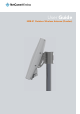
User Guide NRB-51 Outdoor Wireless Antenna (Dundee)
Copyright Copyright© 2016 NetComm Wireless Limited. All rights reserved. The information contained herein is proprietary to NetComm Wireless. No part of this document may be translated, transcribed, reproduced, in any form, or by any means without prior written consent of NetComm Wireless. Trademarks and registered trademarks are the property of NetComm Wireless Limited or their respective owners. Specifications are subject to change without notice. Images shown may vary slightly from the actual product.
Table of Contents Overview ........................................................................................................................................................................................ 4 Introduction ................................................................................................................................................................................................... 4 Target audience........................................................................
Overview Introduction This document provides you the information you need to set up, configure and use the NetComm Wireless NRB-51 Outdoor Wireless Antenna, also referred to as OWA (Dundee) in the document. Target audience This document is intended for system integrators or experienced hardware installers who understand telecommunications terminology and concepts.
Product introduction Product overview Rural and regional homes and businesses, remote commercial sites and metropolitan fringe districts located beyond the reach of fixed line infrastructure rely on mobile networks to access broadband Internet.
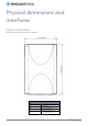
Physical dimensions and interfaces Physical dimensions Below is a list of the physical dimensions of the NRB-51 Figure 1 – NTC-140W Series router Dimensions NRB-51 OWA DIMENSIONS Length 17.4” (442.0 mm) Width 11.22” (285.0mm) Height 6.3” (Assembled with mount) Weight 5.9 lbs with cavity filter 7.1 lbs (Assembled with mount) Table 1 - Device Dimensions Outdoor Wireless Antenna (NRB-51) 6 www.netcommwireless.com UM-00017 rev 1.
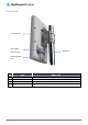
Interfaces Antenna Panel POE Gigabit Ethernet port SIM hatch Install alignment port Figure 2 - Interfaces NO. ITEM DESCRIPTION 1 Antenna panel Includes 2 x pairs Cross polarised antennas and GPS antenna 2 Installation alignment port SMA connector for GPS antenna (not included in package). 6 SIM hatch Open the hatch to insert SIM here 11 POE Gigabit Ethernet port Provides power and data connectivity to the OWA with Ethernet cable Table 2 – Interfaces www.netcommwireless.
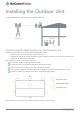
Installing the Outdoor Unit The image below illustrates a typical installation of the WNTD Outdoor Unit. Determining the best location for the Outdoor unit Determining the best location for the Outdoor Wireless Antenna (OWA) involves: 1. Performing a survey of the site using the RF alignment tool and 2. Consulting the customer about positioning based on results of the RF test, aesthetics and any planned renovations to the property that may affect the mounting location.
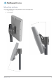
Mounting options Two options available for the mounting brackets as shown in the images below: 1) Slide on the pole 2) Top of the pole www.netcommwireless.com UM-00017 rev 1.
Connecting the Outdoor Unit Powering the Outdoor Unit Power over Ethernet (PoE) is a method of connecting network devices through Ethernet cable where power and data are passed along a single cable. It is therefore a convenient method of powering the OWA. Note that POE-02 is packaged and supplied separately. To power the OWA: 1.
Communicating with the Outdoor unit Diagnostics Tools The following tools may be required to access and perform any admin or testing tasks. adb: console access through the host USB connection (Android tool) fastboot: firmware upgrade through the host USB connection (Android tool) QXDM diag tool and drivers: Qualcomm diagnostic tools and drivers Terminal emulator: emulator software such as PuTTY will be used to connect to the AT command port of the OWA’s Wireless module.
The images below show the correct connection of the components. Note that the white USB to TAG connect ribbon cable is only required for debug and is not part of the actual deployment. RG PORT NUMBER VLAN ID IP ADDRESS RANGE FUNCTION 1 NIL - 2 4001 192.168.11.X Provides connectivity to admin VLAN on the OWA. 3 4002 192.168.12.X Provides connectivity to Data VLAN on the OWA. 4 4003 192.168.13.X Provides connectivity to IMS VLAN on the OWA. Trunk (to OWA) 1.
Firmware Upgrade on Windows 8/8.1/10 PCs Installing the ADB driver Extract the netcomm_nrb51_adb_driver.zip archive to a folder on the PC. On 32-bit Windows systems, run DPInst_x86.exe and on 64-bit Windows systems, run DPInst_x64.exe. Follow the installation wizard steps. Installing the USB driver 1. Double click on the adb-setup-1.3.exe file that you downloaded to install the USB driver. The main screen displays an install confirmation. 2. Type Y and press Enter.
9. Enter the following command from Minimal ADB Tool folder to upgrade the main system image C:\Program Files (x86)\Minimal ADB and Fastboot>update_main.bat The firmware upgrade is complete. 10. Confirm that the upgrade was successful by entering the following command: adb shell rdb get sw.version Outdoor Wireless Antenna (NRB-51) 14 www.netcommwireless.com UM-00017 rev 1.
The software version displayed is 1.0.4.2. Verifying the PDC config To verify the version of the PDC config file, enter the following command: adb shell rdb get system.module.config_version www.netcommwireless.com UM-00017 rev 1.
Admin Shell Session Using SSH The admin shell can be accessed using the admin VLAN (i.e. VLAN 4001). Through this admin interface, ssh session can be setup and like the adb session, any admin activities can be performed, For more details about the command list or details, please contact NetComm Wireless. Using SSH over Ethernet An SSH client is required for Ethernet access.
Connection Manager Connection Manager is a process running on the Application Processor (AP), which communicates with the Baseband Processor (BP) to control the WAN related operations. It uses the QMI protocol over the SMD interface to communicate with the BP. The following QMI services in the BP are used by the Connection Manager. WDS NAS VOICE DMS LOC IMS UIM It reads and writes the connection profiles which reside in the BP and contain the APN details.
Conducting tests on admin VLAN: 1. Make sure Ethernet cable is connected from RG Port #2 to the test PC. This provides connectivity to admin VLAN on the OWA. 2. Ping the admin VLAN >ping 192.168.11.1 Ping should be successful as shown in the figure below. Outdoor Wireless Antenna (NRB-51) 18 www.netcommwireless.com UM-00017 rev 1.
Verification of SIM status: This section is applicable only if SIM is already installed. 1. Make sure that a SIM is inserted before the OWA is powered ON. 2. Ensure that the test PC can access admin VLAN of OWA. 3. Using PuTTY/Tera Term tool, open an SSH client session on the Test PC with following credentials: Host: 192.168.11.1 User name: root Password: When successfully logged in, the terminal window displays “root: ~#” 4.
Useful Commands VLAN details adb shell rdb dump vlan.admin adb shell rdb dump vlan.data adb shell rdb dump vlan.ems adb shell rdb dump vlan.voice WWAN status adb shell rdb dump wwan.0.system_network_status SIM status adb shell rdb dump sim IMEI adb shell rdb dump imei IMS status adb shell rdb dump wwan.0.ims Data Profile adb shell rdb dump link.profile.1 adb shell rdb dump link.profile.1.apn Voice (IMS) profile adb shell rdb dump link.profile.2 SOS profile adb shell rdb dump link.profile.
#ifconfig Log dump #logcat Log file location /var/log/messages Query signal strength adb shell rdb dump signal www.netcommwireless.com UM-00017 rev 1.
Technical Specifications Network Technology o LTE – CAT6, with software upgrade path for 4x4 DL MIMO B2,30 o VoLTE HD Voice Chipset: o Qualcomm MDM9340-1 4 x Antennas (2 x cross-polarized pairs) Antenna gain: o B2 = 13 dBi o B30 = 13 dBi E911 including GPS FOTA: Yes Ports (under cover): o 1 x PoE Gigabit Ethernet RJ45 o Installation alignment port Environmentally protected to IP65 Temp range: -40 to +65⁰C (-40 to 150 F) Dimensions: 17.4” x 11.2” x 6.3” (on mount) Weight: 5.8 lbs (5.
Appendix A: Tables Table 1 - Device Dimensions ......................................................................................................................................... 6 Table 2 – Interfaces ...................................................................................................................................................... 7 www.netcommwireless.com UM-00017 rev 1.
Safety and product care RF Exposure Your device contains a transmitter and a receiver. When it is on, it receives and transmits RF energy. When you communicate with your device, the system handling your connection controls the power level at which your device transmits. This device meets the government’s requirements for exposure to radio waves.
Connection to a car Seek professional advice when connecting a device interface to the vehicle electrical system. Distraction Operating machinery Full attention must be given to operating the machinery in order to reduce the risk of an accident. Product handling You alone are responsible for how you use your device and any consequences of its use. You must always switch off your device wherever the use of a mobile phone is prohibited.
Device heating Your device may become warm during normal use. Faulty and damaged products Do not attempt to disassemble the device or its accessories. Only qualified personnel must service or repair the device or its accessories. If your device or its accessories have been submerged in water punctured or subjected to a severe fall, do not use until they have been checked at an authorised service centre.
Product Warranty For warranty information please visit http://support.netcommwireless.com/support/warranty www.netcommwireless.com UM-00017 rev 1.