Contents Overview................................................................................................................................5 NB1 Package Contents ...................................................................................................6 Minimum System Requirements ......................................................................................7 Do I need a Micro filter? .................................................................................................
Traffic Queuing Configuration ..................................................................................42 Queue Priorities: .................................................................................................42 Configuration: .....................................................................................................42 En-queuing Policy ....................................................................................................42 Configuration: ........................
Appendix A: Specification ...................................................................................................75 ADSL/ATM SUPPORT ..................................................................................75 ENCAPSULATION SUPPORT .....................................................................75 NETWORK SUPPORT .................................................................................75 VoIP ...................................................................................
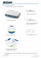
Overview Thank you for purchasing the NetComm NB1 ADSL/ADSL2 Modem Router. NetComm brings you the Next Generation of ADSL technology with ADSL-2*, which boosts ADSL’s performance, improves interoperability, and supports new applications, services and deployment conditions. NetComm’s implementation of ADSL-2* and ADSL-2+* ensures that the NB1 operates with existing ADSL services while delivering optimal performance in all modes of operation.
Minimum System Requirements Before continuing with the installation of your NB1, please confirm that you comply with the minimum system requirements. • Pentium® MMX 233MHz • A CD-ROM Drive • Ethernet card installed with TCP/IP Protocol • OS independent for Ethernet • Web Browser support: • Microsoft Internet Explorer 5.0 (or later versions) • Netscape® Navigator 4.0 (or later versions) • Most popular browsers YML780 Rev1 www.netcomm.com.
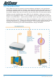
Do I need a Micro filter? Micro filters are used to prevent common telephone equipment, such as phones, answering machines and fax machines, from interfering with your ADSL service. If your ADSL enabled phone line is being used with any other equipment other than your ADSL Modem then you will need to use one Micro filter for each phone device. Splitters may be installed when your ADSL line is installed or when your current phone line is upgraded to ADSL.
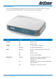
LED Indicators The LED Indicators are located on the front of the unit, they are green in colour, except the Power LED which is red. The meanings are as follows: Label Status Indicates Power On Power is on. Off Power is off. On A valid ADSL connection. Flashing An active WAN session. Flashing Trying to authenticate with ISP’s PPP server. On PPP link is up. Off No PPP link available. Flashing Flashes when data is being sent or received on the Ethernet (LAN) connection.
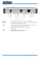
Back Panel Ports Power jack for AC power adaptor 4 x RJ-45 Ports for 10/100 Ethernet LAN Reset factory defaults RJ11 for ADSL connection to telephone line Rear Panel of the NB1 Power Connect the Power Adapt0r that comes with your package. Ethernet 1 x 10/100 Base-T Ethernet jack (RJ-45) to connect to your Ethernet Network card or Ethernet Hub / Switch. Reset To reset your ADSL Router to factory default settings.
Restoring Factory Defaults This feature will reset the Modem to its factory default configuration. Occasions may present themselves where you need to restore the factory defaults on your modem. Typical situations are: • You have lost your username and password and are unable to login to the modem. • You have purchased the modem from someone else and need to reconfigure the device to work with your ISP. • You are asked to perform a factory reset by a member of the NetComm Support staff.
Default Settings LAN (Management) Field Setting Details Static IP Address: 192.168.1.1 * Subnet Mask: 255.255.255.0 * Default Gateway: blank WAN (Internet) Field Setting Details User Name: username@isp Password: **** Protocol: PPPoE VPI: 8* VCI: 35 * IP Address: 192.168.1.1 * Subnet Mask: 255.255.255.0 * Default Gateway: 0.0.0.0 * Modem Access Field Setting Details User Name: admin Password: admin * NB1 User Guide 12 Default Setting.
Connecting your NB1 The NB1 is connected via an Ethernet cable. To connect to your NB1, you will need to have an available Ethernet Port present on your Computer/Notebook or on your network hub or switch. 1. Connect your NB1 to either a computer directly or a network hub or switch using a CAT5 ethernet cable. 2. Connect the power pack to the ADSL Modem and switch on the power switch. 3. Ensure that there is a ETHERNET link light on the NB1. 4.
Configuring your NB1 You will need to log directly into the configuration page of the modem and configure the basic settings for your Internet connection. Your ISP should provide you with the necessary information to complete this step. The settings that you most likely need to change to access the Internet are grouped onto a single EasyConfig page. To configure your modem follow the steps below: Note: Ensure that your PC is setup as a DHCP client.
4. Check with your ISP what Protocol your modem needs to use to connect to the Internet. If unsure, leave the default selection of PPPoE. 5. In the User ID field, enter the Username that your ISP has provided. In the password field, enter the password that your ISP has given you. Note: If your ISP has provided you with Static addressing details you will need to access the Advanced Settings of your modem to configure these. Please refer to the section on Advanced Settings in this manual for instructions.
Computer Hardware Configuration This section provides instructions for configuring the TCP/IP (Network) settings on your computer to work with your Modem. These steps are only required if you are having trouble accessing your Modem. Windows® XP PCs 1. 2. 3. 4. In the Windows task bar, click the Start button, and then click Control Panel. Click on Network & Internet Connections icon. (Category mode only). Click the Network Connections icon.
7. Select Microsoft in the Manufacturers box. 8. Select Internet Protocol (TCP/IP) in the Network Protocols list, and then click OK. You may be prompted to install files from your Windows ME installation CD or other media. Follow the instructions to install the files. If prompted, click OK to restart your computer with the new settings. Next, configure the PC to accept IP information assigned by the modem: 9. Follow steps 1 – 4 above.. 10.
Advanced Settings To access the Advanced Settings of your modem you click on the Advanced Settings link on the EasyConfig web page. To access this page, enter http://192.168.1.1 and login with username ‘admin’ and password ‘admin’. NB1 User Guide 18 YML780 Rev1 www.netcomm.com.
Setup Click the Setup tab. The Setup screen allows you to change current settings for your LAN (Local Area Network), Ethernet Switch and WAN (Wide Area Network). You can also create new connection profiles. YML780 Rev1 www.netcomm.com.
Setup>LAN Configuration Click on the LAN Configuration link under the Setup menu to configure your Local Area Network settings. Interfaces This section displays the available interfaces on your modem that have yet to be configured. The default setting is to have all interfaces in LAN group 1. Note: NB1 User Guide 20 The interface is based on the related NB5 product which allows for LAN groups, however in the case of the NB1 only one LAN group is possible. Click on Configure to configure LAN settings.
Configuring LAN Groups You will be presented with the following screen: IP Settings The IP address is usually 192.168.1.1 but you can change it (e.g. 192.168.0.1 or 10.0.0.1 or 172.16.1.1) to suit any existing network devices you already have installed. The NetMask describes how big your network is, the default 255.255.255.0 will allow for 253 computers and generally does not need to be changed unless to suit existing network requirements.
Option Description Host Name: Required by some ISPs. If the ISP does not provide the Host name, please leave it blank. Domain Name: www.dyndns.org will provide you with a Domain Name. Enter this name in the “Domain Name” field. Apply: Click Apply to save the changes. DHCP stands for Dynamic Host Configuration Protocol. Your Modem has its DHCP Server enabled by default.
If you disable the DHCP server in the Modem you will need to either manually (statically) assign IP address information to each computer or use another device/computer as DHCP server. Note: It is not recommended that you have more than one DHCP server enabled on your network. Option Description Server On: Enables the DHCP server. Start IP: Sets the start IP address of the IP address pool. End IP: Sets the end IP address of the IP address pool.
WAN Setup>New Connection If you click ‘New Connection’ you will see the screen shown below. The Connection setup page requires you to choose the correct settings to work with your ADSL connection as specified by your ISP. The screen will add or remove nonapplicable choices as you change options. There are a few main settings you will need to confirm with your ISP before you can complete this page, these are; • Type of Connection (e.g.
Option Options: VLAN ID Priority Bits 1 Description NAT / Firewall NAT (Network Address Translation allows you to share the public IP address assigned to the WAN (Wide Area Network) interface of your modem with multiple clients on your LAN (Local Area Network). NAT also acts as a basic firewall. The firewall feature protects the PCs on your LAN from malicious attacks from people on the Internet (e.g. DOS attacks).
PPPoE Connection Setup PPP Settings Option Description Username: Enter the username provided by your ISP. Password: Enter the password provided by your ISP. Idle Timeout: Idle timeout means the router will disconnect after being idle for a preset amount of time. The default is 60 seconds. If you set the time to 0, the ADSL connection will remain always connected to the ISP. Keep Alive: If mode is LCP, This is the Keep Alive timer.
Option Description On Demand: If enabled the Idle Timeout field can be modified. On Demand specifies that the modem will connect to the Internet on demand. Default Gateway: Specifies that this connection will be the default gateway for other LAN groups to access the Internet. Enforce MTU: Specifies that the MTU setting will be enforced. Debug: Enable to turn on the debugging mode of your modem. Your ISP may ask you to do this should you be experiencing problems connecting to the Internet.
PVC (Private Virtual Circuit) Settings Option Description VPI: (Virtual Path Identifier) If instructed to change this, type in the VPI value for the initial connection (using PVC 0). Default = 0. VCI: (Virtual Channel Identifier) If instructed to change this, type in the VCI value for the initial connection (using PVC 0). Default = 0. Your modem can support up to 8 PVCs. For example, you could have one PVC (8/35) for your Internet traffic, and another PVC (9/35) for your VoIP traffic.
PPPoA Connection Setup When specifying your connection Type to be PPPoA you are able to change the Encapsulation to either LLC (Logical Link Control) or VC (Virtual Circuit) encapsulation. The default is LLC so do not change this setting unless your ISP instructs you to do so. YML780 Rev1 www.netcomm.com.
Static Connection Setup Option Description Encapsulation: Select the method of encapsulation used by your ISP. The default is LLC, so only change this to VC if your ISP asks you to. IP Address: If your ISP has issued you with a static public IP address, you need to specify it here. (e.g. 210.1.123.123). Mask: The subnet mask specified by your ISP. Default Gateway: The default gateway specified by your ISP. DNS: You have the choice to specify up to three DNS (Domain Name Service) servers.
DHCP Connection Setup Option Description Encapsulation: Select the method of encapsulation used by your ISP from the drop-down list box. Choices vary depending on the mode you select in the Mode field. IP Address: The IP address assigned by an external DHCP server. Mask: The subnet mask assigned by an external DHCP server. Gateway: The gateway assigned by your DHCP server.
WAN Setup>Modem Here you can choose one of four ADSL handshake types, typically MMode (Multimode) will work on Australian ADSL lines. You should not need to change this setting unless advised by your ISP. Option Description T1413: Full-Rate (ANSI T1.413 Issue 2) with line rate support of up to 8 Mbps downstream and 832 Kbps upstream. GDMT: Full-Rate (G.dmt, G992.1) with line rate support of up to 8 Mbps downstream and 832 Kbps upstream. GLITE: G.lite (G.992.2) with line rate support of up to 1.
Logout Click Log Out to logout of the modem’s configuration interface. YML780 Rev1 www.netcomm.com.
Advanced The Advanced menu allows you to configure a number of features of your modem. This section deals with these features. NB1 User Guide 34 YML780 Rev1 www.netcomm.com.
Advanced>UPnP Your modem is Universal Plug ‘n Play Capable, for security this feature is disabled by default. The UPnP architecture is a distributed, open networking architecture that leverages TCP/IP and the Web to enable seamless proximity networking in addition to control and data transfer among networked devices in the home, office, and everywhere in between.
Advanced>SNTP SNTP (Simple Network Time Protocol) allows your modem to update its time automatically using an SNTP server. To enable this feature, click the Enable SNTP tick box. NB1 User Guide 36 YML780 Rev1 www.netcomm.com.
Option Description Primary, Secondary, Tertiary SNTP Servers This allows you to enter three different SNTP server addresses. If one of these servers is unavailable your modem will use an alternative. An example of an NTP server on the Internet is 128.250.36.3. Timeout: The number of seconds your modem will attempt to connect to an SNTP server before trying an alternative server should the server you are trying to connect to be unavailable.
Advanced>SNMP The Simple Network Management Protocol (SNMP) allows a network administrator to monitor a network by retrieving settings on remote network devices. The network administrator typically runs an SNMP management station program such as MIB browser on a local host to obtain information from an SNMP agent such as the router you use now. Option Description Vendor OID: The enterprise OID to which the system belongs to. Enable SNMP Agent: Enabled by default.
Option Description Traps Destination IP: The IP address of the SNMP management device. Trap Community: Used when sending SNMP traps to another device. Trap Version: Version 1 or 2c. Apply: Click Apply to save the changes. YML780 Rev1 www.netcomm.com.
Advanced>IPQoS IP QoS (Quality of Service) allows you to set priorities for traffic travelling through your modem. For example, you may want to prioritize your UDP traffic over your TCP traffic. Typical UDP traffic would be your VoIP (Voice over Internet Protocol) traffic. This section describes how to make use of your modem’s IPQoS feature. The NB1 should have two primary sections for setting up IP QoS services: 1. A QoS setup page to configure the upstream/downstream connection queue priorities, and 2.
Transmit queues associated with LAN connection The high priority queue has strict priority over the medium and low priority queue, and therefore can exhaust all available bandwidth. The web UI will allow the user to select the weights of the medium and low priority queues in increments of 10 percent so that the sum of the weights of the 2 queues is equal to 100 percent.
Traffic Queuing Configuration Based on the TOS (DSCP) marking, the NB1 shall prioritize the traffic servicing on the outgoing interface (facing the Access Network) using a 3-band priority mechanism as described below. Queue Priorities: One Expedited Forwarding (EF) Queue: High Priority queue with non-preemptible service. The EF queue is always scheduled first prior to the medium and low priority queues and runs to completion Two Queues (Medium and Low Priority) with Weighted Round Robin service.
WRR Queue Scheduler for Medium and Low priority queues The L and M weights will be configured from the Web UI as stated above in 1.) Queue Priorities. A service scheduling array will be pre-computed for the Medium and Low priority queues based on the user configurable weights assigned to these queues. Each array slot corresponds to a scheduling cycle.
The four TOS bits (the ‘TOS field’) are defined as: Binary Meaning 1000 Minimize delay (md) 0100 Maximize throughput (mt) 0010 Maximize reliability (mr) 0001 Minimize monetary cost (mmc) 0000 Normal Service TOS Bits Means Linux Priority Queue Priority Band 0x0 0 Normal Service 0 Best Effort 2 0x2 1 Minimize Monetary Cost 1 Filler 2 0x4 2 Maximize Reliability 0 Best Effort 2 0x6 3 mmc+mr 0 Best Effort 2 0x8 4 Maximize Throughput 2 Bulk 1 0xa 5 mmc+mt 2 Bulk
Advanced>Port Forwarding Port Forwarding is necessary because NAT [=Network Address Translation] only forwards traffic from the Internet to the LAN if a specific port mapping exists in the NAT translation table. Because of this, the NAT provides a level of protection for computers that are connected to your LAN. However, this also creates a connectivity problem when you want to make LAN resources available to Internet clients, which you may want to do to play network games or host network applications.
The reason for this is that when using NAT, your publicly accessible IP address will be used by and point to your router, which then needs to deliver all traffic to the private IP addresses used by your PCs. The Internet Assigned Numbers Authority (IANA) is the central coordinator for the assignment of unique parameter values for Internet protocols. Port numbers range from 0 to 65535, but only ports numbers 0 to 1023 are reserved for privileged services and are designated as “well-known ports”.
Easy Port Forwarding: Applying Pre-Defined Rules Available pre-defined rules are categorised according to the application type. Click the Radio Button adjacent to the appropriate Category, and then select the required application name. Click on the Add button to move the application into the Applied Rules box. In the example shown on the previous page, ‘Delta Force’ has been selected from the list of Available Rules and is about to be copied to Applied Rules.
DMZ Settings A DMZ (demilitarized zone) is a computer host or small network inserted as ‘neutral territory’ between a private LAN and the Internet. It prevents outside users from getting direct access to LAN computers while still being able to access services hosted on the designated DMZ Computer. When using NAPT to share your internet connection, LAN computers will still be able to access the Internet when the DMZ host is enabled.
Advanced Port Forwarding: Creating Custom Rules Click the Custom Port Forwarding link to setup a custom rule. If there is no pre-defined Port Forwarding Rule for a particular application, a User Rule can be created which defines the required Port(s), Protocol(s) and Internal Port forwarding rules. To create a custom rule you will need to know the specific port number(s) and port type [UDP or TCP] that the application requires. These will be the outside port numbers.
Option Description Source IP Address: The client on the Internet sending the data (e.g. 202.44.55.66). Note, if you do not know the IP address of the client use 0.0.0.0 for any client on the Internet. Source Netmask: The subnet mask of the client connecting to you. Note, if you do not know the Netmask use 0.0.0.0. Destination IP Address: The LAN IP address of the device on your network to which packets of data will be forwarded to (e.g. 192.168.1.2).
Advanced>IP Filters The IP filters page allows you to specify Normal Port Forwards, Block ALL traffic to specific LAN Clients or specify Custom IP filters that will control the flow of data across the router.
Advanced>LAN Clients LAN Client names are a way of applying specific Port-forwarding and Access Control rules to individual computers on the LAN. If DHCP is used, all DHCP clients are automatically assigned and are designated as a LAN client. To add a LAN client, click Advanced>LAN Clients. Option Description Select LAN Group: Select the LAN group you would like to add a LAN client to. Enter IP Address: Enter the IP address of the LAN client to be added. Hostname: Enter the Hostname.
Advanced>Bridge Filters Bridge filtering enables rules to be defined which allow or deny data to pass through the Router based on the source and destination Bridge address and data type of each data frame. To access Bridge Filters Control, click on Advanced>Bridge Filters.
Edit or Delete Bridge Filter Rules To edit an existing Bridge Filter Rule, click the radio button adjacent to the Filter Rule name. The Rule will then appear in the top half of the Bridge Filter control screen where it can be edited. When editing is complete, click ‘Add’ to return the Rule to the list of existing rules. To delete Bridge Filter Rules, click on the ‘Delete’ tick box; multiple deletions can be made by shift-clicking Delete tick boxes; Select All will select every rule.
Advanced>Multicast IGMP [=Internet Group Management Protocol] Multicast enables communication between a single sender and multiple receivers on a network. It is used when data needs to be sent from one to many devices. Typical uses might include the updating of mobile personnel from a home office or the periodic publishing of an online newsletter. Multicasting provides efficiencies which enable it to use less network bandwidth than the sending of the same data by other means [e.g. SMTP].
Advanced>Static Routing If the Router is required to serve more than one network, you will need to set up a Static Route between the networks. Static routing can be used to allow users from one IP domain to access the Internet through the Router in another domain. A Static Route provides the defined pathway that network information must travel to reach the specific host or network which is providing Internet access . To access the Static Routing controls, click on Advanced> Static Routing.
Advanced>Dynamic Routing Dynamic Routing makes use of the RIP Protocol to allow the ADSL Router to automatically adjust to physical changes in the network. The NB1, using the RIP protocol, will determine the network packet route based on the least number of hops between the Source and the Destination. The RIP protocol regularly broadcasts routing information to other Routers on the network and is part of the IP Suite. To access Dynamic Routing click Advanced>Dynamic Routing.
Advanced>Access Control Use Access Control to configure advanced security functions by customising the Modem Firewall. The default ‘Firewall On’ setting blocks all anonymous Internet traffic. Access control enables the user to selectively direct such traffic, for example to a Web Host in the DMZ or to specific ports opened for such applications as Web, Telnet or FTP. CAUTION: This dialog box indicates that you should not disable LAN Web Access or else you might not be able to connect to the device.
Tools The Tools section allows you to save the configuration, restart the gateway, update the gateway firmware, setup user and remote log information and run Ping and Modem tests. YML780 Rev1 www.netcomm.com.
Tools>System Commands System commands allow you to carry out basic system actions. Press the button to execute a command. Here you will find the following functions: • Save All • Restart • Restore Defaults (same as pressing and holding the button on the back to clear and reset to factory default. Note: NB1 User Guide 60 If you Restore Defaults you will need to reconfigure your internet connection settings, ISP Username & Password etc. YML780 Rev1 www.netcomm.com.
Tools>User Management User Management is used to change your NB1’s User Name or Password. Option Description User Name: Default is ‘admin’. Password: Default is ‘admin’. Idle Timeout: If there is no activity by the admin user logged into the modem for the number of minutes specified in this field, the user will be required to login again. Apply: Click Apply to save the changes. WARNING: It is strongly recommended that you change the default username and password to something unique.
Tools>Update Firmware To update your NB1’s firmware, browse an update image file or configuration file and then click the Update Gateway button. Additionally, you may download your configuration file from the system by clicking “Get Configuration” so that you can store a backup of your configuration to restore it at a later date. NB1 User Guide 62 YML780 Rev1 www.netcomm.com.
Tools>Ping Test The Ping test allows you to ping local and remote IP addresses to check for connectivity directly from the NB1 to the Internet or to a computer on your Network. You must make certain that the IP address that you ping will actually respond to a ping before interpreting the results of the ping. Note: Computers and Network devices can be configured to communicate even though they do not respond to a ping, this can sometimes be done for security. YML780 Rev1 www.netcomm.com.
Tools>Modem Test This test can be used to check whether your Modem is properly connected to the Network. This test may take a few seconds to complete. To perform the test, select your connection from the list and press the Test button. Note: NB1 User Guide 64 Errors or failures on this test do not specifically mean your connection is faulty, only your ISP can tell you if these tests should pass or fail. YML780 Rev1 www.netcomm.com.
Tools>Log out By clicking on Log Out, you will log out of the N1. Click the Log Out button will take you back to the login screen. Use the following procedures to log out. 1. Select Log Out from the left-hand column. You will be prompted to confirm in the screen shown above. 2. Confirm by clicking the Log Out button at the bottom-right corner. You will be taken back to the login screen (cross-reference). YML780 Rev1 www.netcomm.com.
Status The Status section allows you to view the Status/Statistics of different connections and interfaces. NB1 User Guide 66 YML780 Rev1 www.netcomm.com.
Status>Network Statistics You can view data statistics for your Ethernet ports combined or for your ADSL port in these pages. Note: The statistics will be reset on loss of power or Reboot/Reset. YML780 Rev1 www.netcomm.com.
Status>Connection Status Here you can view the connection status of your Internet connection (usually ‘PPPoE’). You can also see the Public IP address that has been assigned to your modem as well as other information about the connection. NB1 User Guide 68 YML780 Rev1 www.netcomm.com.
Status>DHCP Clients The DHCP Clients page shows the MAC address, IP Address, Host Name and Lease Time assigned to other computers in your network by the modem. YML780 Rev1 www.netcomm.com.
Status>Modem Status The Modem Status page shows the modem status and DSL statistics. NB1 User Guide 70 YML780 Rev1 www.netcomm.com.
Status>Product Information The Product Information page shows the product information and software versions. YML780 Rev1 www.netcomm.com.
Status>System Log The System Log page shows the events triggered by the system. NB1 User Guide 72 YML780 Rev1 www.netcomm.com.
EasyConfig The EasyConfig menu takes you to the EasyConfig page. This is the page you originally configured your modem with. YML780 Rev1 www.netcomm.com.
Help This menu provides information on various features of your modem. Click the hyperlinks to access the information. NB1 User Guide 74 YML780 Rev1 www.netcomm.com.
Appendix A: Specification ADSL/ATM SUPPORT • ANSI T1.413 issue 2 • ITU-T G.992.1 (G.dmt) and G.992.2 (G.lite) compliant • ADSL2/2+, G.992.3/G.992.
SECURITY • NAT for Basic Firewall and sharing • Packet Filtering Firewall Support • Stateful Packet Inspection Support • Protection against Denial of Service attacks • Password Authentication to Modem MANAGEMENT SUPPORT • Web-based HTTP management GUI (LAN or Remote) • TFTP/FTP Support For Firmware Upgrade • Web-based Firmware Upgrade (Local) • Soft Factory Reset Button via Web GUI • Diagnostic Test (DSL, OAM, Network, Ping Test) • Telnet/CLI (Read Only) • SNMP • Syslog Support HAR
Appendix B: Cable Connections This cable information is provided for your reference only. Please ensure you only connect the appropriate cable into the correct socket on either this product or your computer. If you are unsure about which cable to use or which socket to connect it to, please refer to the hardware installation section in this manual. If you are still not sure about cable connections, please contact a professional computer technician or NetComm for further advice.
Straight and crossover cable configuration There are two types of the wiring: Straight-Through Cables and Crossover Cables. Category 5 UTP/STP cable has eight wires inside the sheath. The wires form four pairs. Straight-Through Cables has same pinouts at both ends while Crossover Cables has a different pin arrangement at each end. In a straight-through cable, wires 1,2,3,4,5,6,7 and 8 at one end of the cable are still wires 1~8 at the other end.
RJ11 connector and cable An RJ-11 connector is the small, modular plug used for most analog telephones. It has six pin slots in the head, but usually only two or four of them are used. RJ-11 Connector Pin Assignment 1 2 3 4 5 6 Normal Assignment Not Connected Not connected Line Line Not Connected Not Connected Figure 5 605 to RJ-11 adapter The 605 to RJ-11 adaptor is provided to comply with the older 610 Telstra wall socket.
Appendix C: Glossary 10BASE-T A designation for the type of wiring used by Ethernet networks with a data rate of 10 Mbps. Also known as Category 3 (CAT 3) wiring. See also data rate, Ethernet. 100BASE-T A designation for the type of wiring used by Ethernet networks with a data rate of 100 Mbps. Also known as Category 5 (CAT 5) wiring. See also data rate, Ethernet. ADSL Asymmetric Digital Subscriber Line. The most commonly deployed type of DSL for home users.
CO Central Office A circuit switch that terminates all the local access lines in a particular geographic serving area; a physical building where the local switching equipment is found. xDSL lines running from a subscriber’s home connect at their serving central office. DHCP Dynamic Host Configuration Protocol DHCP automates address assignment and management.
Filtering To screen out selected types of data, based on filtering rules. Filtering can be applied in one direction (upstream or downstream), or in both directions. filtering rule A rule that specifies what kinds of data a routing device will accept and/or reject. Filtering rules are defined to operate on an interface (or multiple interfaces) and in a particular direction (upstream, downstream, or both).
in-line filter See Microfilter Internet The global collection of interconnected networks used for both private and business communications. intranet A private, company-internal network that looks like part of the Internet (users access information using web browsers), but is accessible only by employees. IP See TCP/IP. IP address Internet Protocol address The address of a host (computer) on the Internet, consisting of four numbers, each from 0 to 255, separated by periods, e.g., 209.191.4.240.
network A group of computers that are connected together, allowing them to communicate with each other and share resources, such as software, files, etc.A network can be small, such as a LAN, or very large, such as the Internet. network mask A network mask is a sequence of bits applied to an IP address to select the network ID while ignoring the host ID. Bits set to 1 mean “select this bit” while bits set to 0 mean “ignore this bit.” For example, if the network mask 255.255.255.
remote In a physically separate location. For example, an employee away on travel who logs in to the company’s intranet is a remote user. RIP Routing Information Protocol The original TCP/IP routing protocol. There are two versions of RIP: version and version II. RJ-11 Registered Jack Standard-11 The standard plug used to connect telephones, fax machines, modems, etc. to a telephone jack. It is a 6-pin connector usually containing four wires.
TCP/IP Transmission Control Protocol/Internet Protocol The basic protocols used on the Internet. TCP is responsible for dividing data up into packets for delivery and reassembling them at the destination, while IP is responsible for delivering the packets from source to destination. When TCP and IP are bundled with higher-level applications such as HTTP, FTP, Telnet, etc., TCP/IP refers to this whole suite of protocols. Telnet An interactive, character-based program used to access a remote computer.
WAN Wide Area Network Any network spread over a large geographical area, such as a country or continent. With respect to the My ADSL Modem, WAN refers to the Internet. Web browser A software program that uses Hyper-Text Transfer Protocol (HTTP) to download information from (and upload to) web sites, and displays the information, which may consist of text, graphic images, audio, or video, to the user. Web browsers use Hyper-Text Transfer Protocol (HTTP).
Appendix D: Registering your NetComm Product All NetComm Limited (“NetComm”) products have a standard 12 month warranty from date of purchase against defects in manufacturing and that the products will operate in accordance with the specifications outlined in the User Guide. However some products have an extended warranty option (please refer to packaging).
Appendix E: Legal & Regulatory Information This manual is copyright. Apart from any fair dealing for the purposes of private study, research, criticism or review, as permitted under the Copyright Act, no part may be reproduced, stored in a retrieval system or transmitted in any form, by any means, be it electronic, mechanical, recording or otherwise, without the prior written permission of NetComm Limited.
The warranty is automatically voided if: 1. You, or someone else, use the product, or attempts to use it, other than as specified by NetComm; 2. The fault or defect in your product is the result of a voltage surge subjected to the product either by the way of power supply or communication line, whether caused by thunderstorm activity or any other cause(s); 3. The fault is the result of accidental damage or damage in transit, including but not limited to liquid spillage; 4.