Contents Overview ........................................................................................................................ 4 Package Contents ........................................................................................... 4 Connecting via USB or Ethernet? .................................................................... 5 Do I need a Micro filter? ................................................................................... 7 LED Indicators ..............................
Misc Configuration ......................................................................................... System Log .................................................................................................... Code Update .................................................................................................. Status ............................................................................................................. Router ........................................................
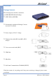
Overview Section Overview Package Contents The following items should be contained in your NB1300 ADSL Modem Package: ❒ ADSL Modem (NB1300) ❒ Documentation include this Package Contents note and a User Guide ❒ Power adaptor (12V AC / 1Amp) ❒ Telephone line cable (RJ11) and 605 to RJ11 Adaptor ❒ Crossover network cable (RJ45) ❒ USB Cable ❒ Microfilter ❒ NetComm Communications CD-ROM (CRS767) Check the contents of your package and, if any parts are missing or damaged, please contact your Dealer. www.
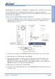
Connecting via USB or Ethernet? Connecting your NB1300 ADSL Modem via Ethernet 1. Connect your NB1300 to either a computer directly or a network hub or siwtch using cat5 ethernet cables. You need to ensure you are using the correct type of etherent cable - ie straight through or crossover. 2. Connect the power pack to the NB1300 ADSL Modem and switch on the power switch. 3. Ensure that there is a LAN link light on the NB1300. 4.
Overview Section Connecting your NB1300 ADSL Modem via USB 1. Connect the power pack to the NB1300 ADSL Modem and switch on the power switch. 2. Connect your NB1300 to a computer directly via USB cable. 3. The Add New Hardware Wizard will launch and prompt you to provide a driver for your NB1300 ADSL Modem. Insert the CD ROM provided. 4. Connect one end of the ADSL phone line to the NB1300 ADSL Modem and the other end to the wall socket.
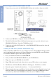
Do I need a Micro filter? Splitters may be installed when your ADSL line is installed or when your current phone line is upgraded to ADSL. If your telephone line is already split you will not need to use a Microfilter - check with your ADSL service provider if you are unsure. Each micro filter is connected in-line with your telephone or fax machine so that all signals pass through it. Telephones and/or facsimiles in other rooms that are using the same extension will also require Microfilters.
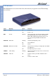
Overview Section LED Indicators The LED Indicators are located on the front of the unit, they are green in colour. The meanings are as follows: Label Meaning Status Indicates: PWR Power On Power is on Off Power is off RDY Ready Flashing Unit is powered up correctly when pulsing steadily. ON or OFF during reboot or when unit switched OFF. If ON or OFF permanently then there is an error. Try powering unit OFF then ON after a minute. WAN LNK WAN Link Flashing Link being attempted by router.
Using Easy Config NetComm’s Easy Config software is supplied to help you to configure your NB1300 for a quick connection to the Internet. You can use one of the default profiles provided or you can use a profile that is provided by your Internet Service Provider (e.g. via Email, floppy disk or CDROM). Once you have configured your router with easy config you can then choose an appropriate Connection Configuration to connect your NB1300 to your Network or Computer.
Overview Section Factory Defaults The following table lists the Factory Defaults of your NB1300 ADSL Modem: Field Setting Details LAN IP address: 192.168.1.1 LAN Subnet Mask: 255.255.255.0 DHCP Server: Enabled User Name: admin Password: password Main Function: Router (Bridge Disabled) WAN connection type: PPPoE LLC VPI: 8 VCI: 35 Note: These defaults may change with firmware updates and factory changes, please consult the NetComm website to check for the latest defaults.
Configuration Types This section is supplied to help you connect your NB1300 ADSL Modem quickly to your network or Windows computer. The following are the most common configurations for using your NB1300 ADSL Modem. ■ Basic ADSL Modem - Ethernet ■ Basic ADSL Modem - USB ■ Gateway - Ethernet ■ Gateway - USB Note: If the NB1300 has already been used, we strongly recommend you reset and flush all settings of the unit by pressing and holding the RESET button on the rear of the modem for 10 seconds.
Basic ADSL Modem - Ethernet Configuration Use this configuration if you: ■ Have been told to use the “ADSL Modem” Easy Config Profile, or ■ Want to connect this device to another router, or ■ Want to use your ISP’s software to log on to the Internet directly (not sharing) and your computer will use a Public IP address, and ■ DO NOT need the NB1300 to share your Internet service ( You can still use windows ICS to share your Internet Service), and Basic Ethernet ■ Do not require your computer to be protecte
Before continuing, ensure you have the following items and information ready: ■ A computer with a Network Interface Card installed or a router (such as the NetComm NB3100). ■ A Crossover UTP cable. ■ A telephone line with ADSL service enabled. ■ User Name, Password, VPI, VCI, encapsulation and DNS server settings for your ADSL account (ask your ISP if unsure). These are not needed for the NB1300, but are required for the computer or router that it will be connected to.
a. Power on the ADSL Router and launch a web browser, such as Internet Explorer or Netscape Navigator, browse to the address http://192.168.1.1. b. Enter the correct user name and password to access the Configuration tool. The default user name and password are as below. User Name : Password : Note: admin password You must click the Submit button on every page that you make changes on and when you have made all your changes click the Save Setting and Reboot button from the bottom of the menu.
Setting Details Service name: Blank ❖ User Name: Blank ❖ Password: Blank ❖ Disconnect timeout: 0❖ Mode/Wan Connection Type: 1483 Bridged IP LLC VPI: 8❖ VCI: 35 ❖ Static IP Address: 192.168.241.101 ❖ Subnet Mask: 255.255.255.0 ❖ Default Gateway: 0.0.0.0 ❖ Bridge mode: Enabled ❖ Default Setting. Although in most cases you will not be required to alter these default settings for your NB1300, your ISP may identify specific settings to enable connection to their service.
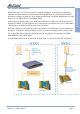
Basic Ethernet Operational Diagram for ADSL Modem Configuration www.netcomm.com.au Page 16 Rev.
Basic ADSL Modem - USB Configuration Use this configuration if you: ■ Have been told to use the “ADSL Modem” Easy Config Profile, or ■ Want to connect this device to another router, or ■ Want to use your ISP’s software to log on to the Internet directly (not sharing) and your computer will use a Public IP address, and ■ DO NOT need the NB1300 to share your Internet service ( You can still use windows ICS to share your Internet Service), and ■ Do not require your computer to be protected (via NAT) from the I
Before continuing, ensure you have the following items and information ready: ■ A computer with a Network Interface Card installed or a router (such as the NetComm NB3100). ■ A Crossover UTP cable. ■ A telephone line with ADSL service enabled. ■ User Name, Password, VPI, VCI, encapsulation and DNS server settings for your ADSL account (ask your ISP if unsure). These are not needed for the NB1300, but are required for the computer or router that it will be connected to.
Step 2: Configuring the NB1300 After connecting all the ADSL Router cables you can either configure your NB1300 using the Easy Config software provided (Refer to page 9) or complete the following manual configuration instructions: a. Power on the ADSL Router and launch a web browser, such as Internet Explorer or Netscape Navigator, browse to the address http://192.168.1.1. b. Enter the correct user name and password to access the Configuration tool. The default user name and password are as below.
Basic USB Field Setting Details Service name: Blank ❖ User Name: Blank ❖ Password: Blank ❖ Disconnect timeout: 0❖ Mode/Wan Connection Type: 1483 Bridged IP LLC VPI: 8❖ VCI: 35 ❖ Static IP Address: 192.168.241.101 ❖ Subnet Mask: 255.255.255.0 ❖ Default Gateway: 0.0.0.0 ❖ Bridge mode: Enabled ❖ Default Setting. Although in most cases you will not be required to alter these default settings for your NB1300, your ISP may identify specific settings to enable connection to their service.
Operational Diagram for ADSL Modem Configuration Basic USB Rev. 1 - YML672 NB1300_2 ADSL Modem www.netcomm.com.
Gateway - Ethernet Configuration Use this configuration if you: ■ Have been told to use Easy Config “ISP Profile 1, 2, 3, 5 or 6 ”, or ■ Were told by your ISP to use this Configuration with another Easy Config profile, or ■ Have at least one computer with an Ethernet Networking socket, and / or ■ Want to share your Internet Service with more than one computer. ■ Want your computers to be protected by the NB1300 (via NAT). Gateway Ethernet ■ You want your computers to use Private IP addresses.
Step 1: Connecting your computer to the NB1300 Note: This unit should only be connected to the Telecommunications Network through a line cord which meets the requirements of ACA TS008. b. Connect one end of the ADSL phone line to the NB1300 ADSL Modem and the other end to the wall socket. c. Connect the power pack to the NB1300 ADSL Modem and switch on the power switch. d. Ensure that there is a LAN link light on the NB1300. e.
b. Enter the correct user name and password to access the Configuration tool. The default user name and password are as below. User Name : Password : Note: admin password You must click the Submit button on every page that you make changes on and when you have made all your changes click the Save Setting and Reboot button from the bottom of the menu. Gateway Ethernet c. Click on the One Page Setup link under the Basic menu.
Setting Details Service name: Any name to describe your ISP User Name: Your ISP will provide a case sensitive User Name in a format similar to your email address. Contact your ISP for details Password: Enter your Password as supplied by your Service Provider (characters are usually all lower case) Disconnect timeout: 0❖ Mode/Wan Connection Type: PPPoE LLC or PPPoA (Your ISP should advise which WAN Type) VPI: 8❖ VCI: 35 ❖ Static IP Address: 192.168.241.101 ❖ Subnet Mask: 255.255.255.
Open the Control Panel and double click on the Network icon. Scroll down to select TCP/IP-> Ethernet Card and click on the Properties button. Gateway Ethernet Your DNS numbers are specific to your ISP and should be notified along with your User Name and Password. Note: When using Internet Explorer as a web browser, click on the “Tools” menu and select “Internet Options”. Select the “Connections” tab and click on the “LAN Settings” button.
Operational Diagram for Ethernet Gateway Configuration Gateway Ethernet Rev. 1 - YML672 NB1300_2 ADSL Modem www.netcomm.com.
Gateway - USB Configuration Use this configuration if you: ■ Have been told to use Easy Config “ISP Profile 1, 2, 3, 5 or 6 ”, or ■ Were told by your ISP to use this Configuration with another Easy Config profile. ■ Wish to use the NB1300 with a computer that does not have an Ethernet socket. This computer will use a Private IP address and will be protected from the Internet by the NB1300 (via NAT).
Step 1: Connecting your computer to the NB1300 Note: This unit should only be connected to the Telecommunications Network through a line cord which meets the requirements of ACA TS008. a. Place the CD-ROM provided into your CD-ROM drive. c. Windows will detect the new hardware and launch a New hardware Wizard. When prompted to search for drivers choose “Specify location”. d. Browse the drive letter of your CD-ROM drive and locate the “USB driver” folder. E.g.
Note: You must click the Submit button on every page that you make changes on and when you have made all your changes click the Save Setting and Reboot button from the bottom of the menu. Gateway USB c. Click on the One Page Setup link under the Basic menu. You do not need to change the LAN settings unless you need the NB1300 to work with an existing network on a subnet other than 192.168.1.x. You will need to Change your WAN and VC settings as provided by your ISP.
Setting Details Service name: Any name to describe your ISP. User Name: Your ISP will provide a case sensitive User Name in a format similar to your email address. Contact your ISP for details. Password: Enter your Password as supplied by your Service Provider (characters are usually all lower case). Disconnect timeout: 0❖ Mode/Wan Connection Type: PPPoE LLC or PPPoA VPI: 8❖ VCI: 35 ❖ Static IP Address: 192.168.241.101❖ Subnet Mask: 255.255.255.0❖ Default Gateway: 0.0.0.
Gateway USB Operational Diagram for USB Gateway Configuration www.netcomm.com.au Page 32 Rev.
Advanced Configuration for your NB1300 How to make changes The NB1300 utilises a Web based interface for configuration, this means that you do not need to load drivers (unless using USB) and configuration is always performed via a Web browser (such as Internet Explorer or Netscape Navigator). For each configuration page there is a Submit button to store the changes for that page before you move on to the next page.
The configuration page is split into two sections, Simple mode (default) and Advanced mode. When you log into the router it will be in simple mode. This provides enough configuration for the majority of connections. Main Menu - (Simple) Advanced The following is displayed in the left hand panel when you first log into the NB1300: www.netcomm.com.au Page 34 Rev.
Basic Menu One Page Setup The One Page setup page is designed to make the most commonly required configuration fields available all in one place. For most installations you will only need to use the one-page setup to configure the unit. One-Page setup fields all apply to Virtual Circuit zero only (see section on Multiple Virtual Circuits elsewhere in this manual for more information). Advanced LAN: This the Local Area Network IP address of the NB1300, by default this is set to 192.168.1.
Password - This is the password provided by your ISP for your Internet connection. It is usually only required for connection types that use PPP. Disconnect timeout - If no activity is recorded on the network the NB1300 will disconnect the line after this many seconds, the max is 32767 seconds (about 10 hours).
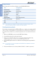
Router The Router page shows the firmware versions and WAN and LAN interface status. WAN: These fields display the current IP address, Subnet Mask and MAC address for the WAN (ADSL) interface. This address is supplied by your ISP either automatically or using a static assigned address. LAN: These fields display the IP address, Subnet Mask and MAC address for the LAN interface. Number of Ethernet Devices Connected to the DHCP Server: This field displays the number of DHCP clients connected to the NB1300.
ADSL Advanced The ADSL Status page shows the ADSL physical layer status. ADSL Line Status: This field displays the ADSL connection process and status. ADSL Modulation: This field displays the ADSL modulation status for G.dmt or T1.413. ADSL Annex Mode: This field displays the ADSL annex modes for Annex A or Annex B. ADSL Startup Attempts: This field displays the ADSL connection attempts after loss of showtime. Elapsed Time: This field displays the time of the modem has been in operation.
PPP The PPP Status page shows the status of PPP for each PPP interface. See PPP: These fields display the following information on each PPP interface: Advanced ■ Connection Name (user defined) ■ Interface (PVC) ■ Mode (PPPoE or PPPoA) ■ Status (Connected or Not Connected) ■ Packets Sent ■ Packets Received ■ Bytes Sent ■ Byte Received.
Main Menu - (Advanced) Advanced Advanced One Page Setup See 'Main menu - Simple' for full details of the One Page Setup. Hide Advanced settings Select this option to hide the advanced settings of the NB1300. Pressing this will display the Simple settings. www.netcomm.com.au Page 40 Rev.
Administration The links under the Administration column are associated to the pages that represent the configurations of system and interfaces. Note: When the configurations are changed, please go to the Save Settings page to save the new setting and reboot the board. WAN The WAN configuration page allows the user to set the configuration for the WAN/ADSL ports.
ATM: Service Category: UBR and CBR are supported from the ATM. Bandwidth: Bandwidth setting takes effect only when the CBR is selected. The maximum available bandwidth is from the upstream data rate of ADSL status page. Encapsulation: Bridge IGMP IGMP relay/proxy specification and environment: Support IGMP proxy/relay function for ADSL modem, based on the following requirement and case: ■ On CO side, there must be at least one IGMP querier (router) present. IGMP querier will send IGMP query packet.
MTU: Maximum Transmission Unit indicates the network stack of any packet is larger than this value will be fragmented before the transmission. During the PPP negotiation, the peer of the PPP connection will indicates its MRU and will be accepted. The actual MTU of the PPP connection will be set to the smaller one of MTU and the peer's MRU. The default is value 1492. MSS: Maximum Segment Size is the largest size of data that TCP will send in a single IP packet.
LAN/DHCP Advanced The LAN configuration page allows you to set the configuration for the LAN port. LAN IP Address & Subnet Mask: The default is 192.168.1.1 and 255.255.255.0 you can change it to another private IP address, such as 172.168.0.1, and 255.255.255.0. - For most configurations it is recommended to leave it as default. DHCP Server: System Allocated: The DHCP address pool is based on LAN port IP address plus 12 IP addresses. For example, the LAN IP address is 192.168.1.
DNS The DNS Configuration page allows you to set the configuration of DNS proxy. The NetComm firmware supports DNS proxy. For the DHCP requests from local PCs, the DHCP server will set the LAN port IP as the default DNS server. Thus, all DNS query messages will come into LAN port first. The DNS proxy on the ADSL modem recorded the available DNS servers, and forward DNS query messages to one of DNS server. Rev. 1 - YML672 NB1300_2 ADSL Modem www.netcomm.com.
NAT The NAT Configuration page allows the user to set the configuration for the Network Address Translation. The default setting is Dynamic NAPT. It provides dynamic Advanced Network Address Translation capability between LAN and multiple WAN connections, the LAN traffic is routed to appropriate WAN connections based on the destination IP addresses and Route Table. This eliminates the need for the static NAT session configuration between multiple LAN clients and multiple WAN connections.
NAT Session Name Status: This table displays at the bottom of this page to show all the NAT Session Names with its WAN Interface. Number of NAT Configurations: This filed displays the total number of NAT Sessions Name is entered. Click the link Go back to NAT Configuration to return to the NAT configuration page. Select the NAT option. Select the Session Name and assign the PC IP address, and choose the Add action. Click the Submit button and go to the Save Settings to save this configuration.
Port Forwarding Advanced The Port Forwarding Configuration page allows the user to set the configuration for Port Forwarding. By default all UDP/TCP ports are protected from intrusion. If any specific local PCs need to be mapped to the UDP/TCP port on WAN side, please input the mappings here. Public Port: This field allows the user to enter the port number of the Public Network. Private Port: This field allows the user to enter the port number of the Private Network.
ADSL Configuration The ADSL Configuration page allows the user to set the configuration for ADSL protocols. Rev. 1 - YML672 NB1300_2 ADSL Modem www.netcomm.com.au Page 49 Advanced Trellis: This field allows the user to enable or disable the Trellis Code. By default, it is always enabled. Handshake Protocol: This field allows the user to select the ADSL handshake protocol. Wiring Selection: This field allows the user to enter the wiring selection for the RJ-11.
RIP Configuration Advanced The RIP Per Interface Configuration page allows the user to set the configuration for each Interface (PVCs, PPP Sessions, USB and LAN). Interface: This field allows the user to choose the Interface (PVCs, PPP Sessions, USB and LAN), for the RIP to be configured. Enable: This field allows the user to Enable (Yes) or Disable (No) the specified interface for RIP. Supplier: This field allows the user to select the Supplier Mode (RIP Transmit).
Diagnostic Test The Diagnostic Test page shows the test results for the connectivity of the physical layer and protocol layer for both LAN and WAN sides. Note: on some ADSL services this test may fail despite you have connected correctly. Rev. 1 - YML672 NB1300_2 ADSL Modem www.netcomm.com.au Page 51 Advanced Testing Ethernet LAN Connection: This test checks the Ethernet LAN interface connection. Testing ADSL Synchronization: This test checks the ADSL showtime.
Route Table Advanced The Route Table page displays routing table and allows the user to manually enter the routing entry. The routing table will display the routing status of Destination, Netmask, Gateway, and Interface. The interface br0 means the USB interface; lo0 means the loopback interface; and ppp1 means the PPP interface. The Gateway is the learned Gateway www.netcomm.com.au Page 52 Rev.
MAC Filtering The MAC Filtering configuration page allows the user to set the configuration of IP filtering. Enable and disable MAC filtering by selecting the 'Yes' or 'No' radio buttons. Rev. 1 - YML672 NB1300_2 ADSL Modem www.netcomm.com.au Page 53 Advanced Source MAC: When the bridge filtering is enabled, enter the Source MAC address, select Block and click Add. Then all incoming WAN and LAN Ethernet packets matched with this source MAC address will be filtered out.
Security Admin Password The Admin Password Configuration page allows the user to set the password for administrator. Advanced The Admin password is the same as the FTP password and must be at least 8-characters long for the FTP function to work. User Name: admin Password (default): password www.netcomm.com.au Page 54 Rev.
User Password The User Password Configuration page allows the Admin user to set the password for the general user. When logged in as a general user you can view the basic staus of the NB1300 but you can not make critical changes to the unit. admin Password (default): password Rev. 1 - YML672 NB1300_2 ADSL Modem Advanced User Name: www.netcomm.com.
Misc Configuration Advanced The Miscellaneous Configuration allows the user to set all the miscellaneous configurations. HTTP Server Access: This field allows the user to configure the Web pages can be accessed from. All: When this field is checked, it allows both WAN and LAN access to the Web pages. Restricted LAN: This field allows the Web pages access from LAN side. Restricted WAN Specified IP & Subnet Mask: This field allows the Web access from WAN side with a specify IP and subnet mask.
DHCP Target IP: The DHCP server runs on WAN side. IGMP Proxy: Here is the global setting for IGMP Proxy. If it is enabled, then the enabled IGMP Proxy on WAN PVCs will be working. Otherwise, no WAN PVC can have IGMP Proxy working on it. PPP connect on WAN access: If it is enabled, the PPP session will be automatically established when there is a packet wants to go out the WAN.
System Log The System Log page shows the events triggered by the system. Advanced To clear the System Log simply click on the 'Clear Log' button. To save the System Log, right click in the Log field and select "Select All" then right click again and select "Copy" then paste it to your text editor (Notepad is good).
■ IP Layer ■ ■ ■ ■ IP protocol up PPP IP address PPP Gateway IP address PPP DNS Primary IP address PPP DSN Secondary IP address Advanced Rev. 1 - YML672 NB1300_2 ADSL Modem www.netcomm.com.
Code Update The Code Update page allows the user to upload new firmware to the NB1300. Advanced To upload new firmware: 1. Download the latest firmware image from the NetComm website 2. Save the file to your Desktop or other location 3. Select the Browse button and locate the file saved in step 2 4. Click on the Update button to start the process 5. Once the upgrade has been completed the router will need to reboot. www.netcomm.com.au Page 60 Rev.
Status Router The Router page shows the firmware versions and WAN and LAN interface status. Rev. 1 - YML672 NB1300_2 ADSL Modem www.netcomm.com.au Page 61 Advanced Firmware Version: This field displays the NetComm firmware version number. Showtime Firmware Version: This field displays the NetComm firmware version number. Graphical Interface Version: This field displays the Graphical User Interface version.
ADSL Advanced The ADSL Status page shows the ADSL physical layer status. ADSL Line Status: This field displays the ADSL connection process and status. ADSL Modulation: This field displays the ADSL modulation status for G.dmt or T1.413. ADSL Annex Mode: This field displays the ADSL annex modes for Annex A or Annex B. ADSL Startup Attempts: This field displays the ADSL connection attempts after loss of showtime. Elapsed Time: This field displays the time of the modem has been in operation.
LAN The LAN page shows the information and status of LAN port, DHCP client table, Ethernet link and USB link. Rev. 1 - YML672 NB1300_2 ADSL Modem www.netcomm.com.au Page 63 Advanced LAN: These fields display the IP address, Subnet Mask and MAC address for the LAN interface. Number of Ethernet Devices Connected to the DHCP Server:These fields display the number of connections to the DHCP server as well as the DHCP client table with the assigned IP addresses and MAC addresses.
WAN Advanced The WAN Status page shows the information and status of WAN PVCs. WAN: These fields display the IP address, Subnet Mask and MAC address for the WAN (ADSL) interface. Use the Virtual Circuit selection to selection different PVC for status display. DHCP Release & Renew: This field allows the user to release and renew the WAN IP address in the WAN DHCP Client Enabled (dynamic) mode. www.netcomm.com.au Page 64 Rev.
ATM The ATM Status page shows all the statistics information of ATM cells. Advanced Rev. 1 - YML672 NB1300_2 ADSL Modem www.netcomm.com.
TCP Connections Advanced TCP Status: The TCP Status page shows the statistics for all TCP connections. www.netcomm.com.au Page 66 Rev.
Learned MAC Table The Learned MAC Table page shows the current learned Bridge MAC table. Rev. 1 - YML672 NB1300_2 ADSL Modem www.netcomm.com.au Page 67 Advanced Aging Timeout: This field allows the user to enter the update period for the MAC table.
PPP Advanced The PPP Status page shows the status of PPP for each PPP interface. PPP: These fields display the following information on each PPP interface: ■ Connection Name (user defined) ■ Interface (PVC) ■ Mode (PPPoE or PPPoA) ■ Status (Connected or Not Connected) ■ Packets Sent ■ Packets Received ■ Bytes Sent ■ Byte Received. Connect and Disconnect: This field allows the user to manually connect/disconnect the PPP connection for each PPP interface.
Save Settings and Reboot The Save Settings and Reboot button allows the user to save the new configuration to the flash and reboot the system. When the configurations are changed via the Web pages, the new settings need to be saved into the flash, so it is necessary to go to this Save Settings page to save and reboot the system for the changes to be taken effect. After the Save and Reboot, you will be returned to the onepage setup.
Appendix A - Connection Instructions Connect your NB1300 ADSL Modem via Ethernet 1. Connect your NB1300 to either a computer directly or a network hub or siwtch using cat5 ethernet cables. You need to ensure you are using the correct type of etherent cable - ie straight through or crossover. 2. Connect the power pack to the NB1300 ADSL Modem and switch on the power switch. 3. Ensure that there is a LAN link light on the NB1300. 4.
Connect your NB1300 ADSL Modem via USB 1. Connect the power pack to the NB1300 ADSL Modem and switch on the power switch. 2. Connect your NB1300 to a computer directly via USB cable. 3. The Add New Hardware Wizard will launch and prompt you to provide a driver for your NB1300 ADSL Modem. Insert the CD ROM provided. 4. Connect one end of the ADSL phone line to the NB1300 ADSL Modem and the other end to the wall socket.
Appendex B - Trouble Shooting The following section gives details about troubleshooting issues for your NB1300 ADSL Modem. Problems are divided into different areas to assist you in finding the appropriate solution. General Modem Operation Before continuing, refer to the correct power up sequence to verify that your NB1300 ADSL Modem is operating. Correct power up sequence After you turn on your NB1300 ADSL Modem, the following sequence should occur: 1.
Web Based Interface If you are unable to access the NB1300 ADSL Modem’s Web Based Interface from a computer on your local network, check the following: ■ Check the Ethernet connection between your computer and your NetComm ADSL Modem. ■ Make sure your computer’s IP address is on the same subnet as your ADSL Modem. If you are using the recommended addressing scheme, your computer’s address should be in the range of 192.168.1.1 to 192.168.1.254. Note: If your computer’s IP address is shown as 169.254.x.
Internet / ISP Connection ADSL link If your ADSL Modem is unable to access the Internet, you should first determine whether you have an ADSL link with the service provider. The state of this connection is indicated with the WAN LED. WAN LED is Yellow If your WAN LED is yellow, then you have a good ADSL connection. You can beconfident that the service provider has connected you line correctly and that your wiring is correct.
■ Your ISP may check for your computer's host name. Assign the computer Host Name of your ISP account to your ADSL Modem in the browser-based Setup Wizard. ■ Your ISP only allows one MAC address to connect to Internet, and may check for your computer’s MAC address. In this case, inform your ISP that you have bought a new network device, and ask them to use your ADSL Modem’s MAC address. PPPoE or PPPoA The PPPoA or PPPoA connection can be debugged as follows: 1.
Testing the LAN Path to Your ADSL Modem You can ping the ADSL Modem from your computer to verify that the LAN path to your modem is working. To ping the modem from a computer running Windows 95 or later: 1. From the Windows toolbar, click the Start button and select Run. 2. In the field provided, type Ping followed by the IP address of the ADSL Modem, as in this example: ping 192.168.1.1 3. Click OK.
Testing the Path from Your Computer to a Remote Device After verifying that the LAN path works correctly, test the path from your computer to a remote device. From the Windows run menu, type: PING -n 10 where is the IP address of a remote device such as your ISP’s DNS server. If the path is functioning correctly, replies as in the previous section are displayed.
Appendix C - Glossary ADSL: Asymmetric Digital Subscriber Line (ADSL), as its name indicates, is an asymmetrical data transmission technology with higher traffic rate downstream and lower traffic rate upstream. ADSL technology satisfies the bandwidth requirements of applications which demand .asymmetric. traffic, such as web surfing, file downloads, and telecommuting. Bandwidth: The amount of data that can be transmitted in a fixed amount of time.
PAP/CHAP: Password Authentication Protocol and Challenge Handshake Authentication Protocol (PAP/CHAP). Most ISPs use either one for user identification. If your ISP doesn’t support these two protocols, contact them for an authentication script. PCI: Peripheral Component Interconnect (PCI) is a specification introduced by Intel Corporation that defines a local bus system that allows up to 10 PCI-compliant expansion cards to be installed in the computer.
Registering your NetComm Product To ensure that the conditions of your warranty are complied with, please go to the NetComm web site for quick and easy registration of your product at www.netcomm.com.au Alternatively, you can use a copy of the Warranty Registration Form on the following page and mail it to NetComm Limited, PO Box 1200, Lane Cove NSW 2066. Contact Information If you have any technical difficulties with your product, please do not hesitate to contact NetComm’s Customer Support Department.
Cut along the line Warranty Registration Form Date of Purchase ….......…………...........………................................. Name ….......…………...........………................................. Company ….......…………...........………................................. Address ….......…………...........………................................. …………………….........……........... Tel No ( ) ..............……….…. E-mail Post Code Fax No ( ) .....………....………. ....………...………. ….......…………...........………........................
Product Warranty The warranty is granted on the following conditions: 1. This warranty extends to the original purchaser (you) and is not transferable; 2. This warranty shall not apply to software programs, batteries, power supplies, cables or other accessories supplied in or with the product; 3. The customer complies with all of the terms of any relevant agreement with NetComm and any other reasonable requirements of NetComm including producing such evidence of purchase as NetComm may require; 4.