User Guide NB6, NB6W, NB6Plus4, NB6Plus4W and NB6Plus4Wn ADSL2+ Router
Safety and Precaution Installation • Use only the type of power source indicated on the marking labels. • Use only power adapter supplied with the product. • Do not overload wall outlet or extension cords as this may increase the risk of electric shock or fire. If the power cord is frayed, replace it with a new one. • Proper ventilation is necessary to prevent the product overheating. Do not block or cover the slots and openings on the device, which are intended for ventilation and proper operation.
Contents Before You Use...............................................................................................................................................6 NB6 Series Package Contents....................................................................................................................7 Subscription for ADSL Service....................................................................................................................8 Chapter 1: Overview.................................
Chapter 3: Accessing the Internet...............................................................................................................35 PPP over ATM (PPPoA) Mode...................................................................................................................36 PPP over ATM (PPPoA) IP Extension Mode................................................................................................37 PPP over Ethernet (PPPoE) Mode.......................................................
Quality of Service....................................................................................................................................95 Quality of Service – Bridge QoS.........................................................................................................95 Quality of Service – IP QoS................................................................................................................97 Port Mapping..................................................................
Before You Use Thank you for purchasing a NetComm ADSL2+ Router. NetComm brings you the Next Generation of ADSL technology with ADSL2+*, which boosts ADSL’s performance, improves interoperability, and supports new applications, services and deployment conditions. NetComm’s implementation of ADSL2+* ensures that your Router operates with existing ADSL services while delivering optimal performance in all modes of operation.
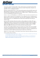
NB6 Series Package Contents Your Package contains the following items: • One NB6, NB6W, NB6Plus4, NB6Plus4W and NB6Plus4Wn Router (all models shown above) • Telephone Cable (RJ-11) • USB Cable (Not available for NB6Plus4 or NB6Plus4Wn) • Power Adaptor (NB6 - 9V AC 1A, NB6W/NB6Plus4/NB6Plus4W and NB6Plus4Wn - 12V AC 1A) NB6 Series ADSL2+ Modem/Router Driver, Manuals and Software CRS889 • CAT-5 UTP Straight Ethernet Network Cable (RJ-45) • Driver and Manual CD • One Quick Start Guide If any o
Subscription for ADSL Service To use the ADSL Router, you have to subscribe to an ADSL service from your broadband service provider. According to the service type you select, you may get various IP addresses: Dynamic IP: If you apply for an on-demand connection, you will be given an Internet account with username and password. You will get a dynamic IP issued by your ISP, such as under PPPoA, PPPoE, or MER mode.
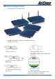
Chapter 1: Overview This chapter provides you with a description for the LEDs and connectors on the front and rear surface of the router. Please take a look at this information, before you use/install this router. YML854 Rev1 ������������������������������������������ NB6, NB6W, NB6Plus4, NB6Plus4W, NB6Plus4Wn User Guide www.netcomm.com.
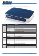
NB6 LED Indicators The LED Indicators are located on the front of the unit, their meanings are as follows: Function Power ADSL PPP Ethernet USB Color Off Solid Green Solid Red Flash Red Off Slow Flash Green Fast Flash Green Solid Green Off Solid Green Off Flash Green Solid Green Off Flash Green Solid Green Definition Power is off. Power is on and the device operates normally. Power on self-test in progress The device enters the console mode of the boot loader.
NB6 Rear Panel The following figure illustrates the rear panel of your ADSL Router: Connector Description Line RJ-11 connector (Telephone line) USB USB connector Reset Reset to factory defaults Ethernet Ethernet RJ-45 connector Power on/off switch Power 9VAC Power connector YML854 Rev1 ������������������������������������������ NB6, NB6W, NB6Plus4, NB6Plus4W, NB6Plus4Wn User Guide www.netcomm.com.
NB6W LED Indicators The LED Indicators are located on the front of the unit, their meanings are as follows: Function Power ADSL PPP Ethernet USB WLAN Color Off Solid Green Solid Red Flash Red Off Slow Flash Green Fast Flash Green Solid Green Off Solid Green Off Flash Green Solid Green Off Flash Green Solid Green Off Flash Green Solid Green Definition Power is off. Power is on and the device operates normally. Power on self-test in progress The device enters the console mode of the boot loader.
NB6W Rear Panel The following figure illustrates the rear panel of your ADSL Router: Connector Description Wireless antenna Power 12VAC Power connector Power on/off switch Reset Reset to factory defaults Ethernet Ethernet RJ-45 connector USB USB connector Line RJ-11 connector (Telephone line) YML854 Rev1 ������������������������������������������ NB6, NB6W, NB6Plus4, NB6Plus4W, NB6Plus4Wn User Guide www.netcomm.com.
NB6Plus4 LED Indicators The LED Indicators are located on the front of the unit, their meanings are as follows: Function Power ADSL PPP Ethernet 1, 2, 3, 4 Color Off Solid Green Solid Red Flash Red Off Slow Flash Green Fast Flash Green Solid Green Off Solid Green Off Flash Green Solid Green Definition Power is off. Power is on and the device operates normally. Power on self-test in progress The device enters the console mode of the boot loader.
NB6Plus4 Rear Panel The following figure illustrates the rear panel of your ADSL Router: Connector Description Reset Reset to factory defaults Power 12VAC Power connector Power on/off switch Ethernet – 1, 2, 3, 4 Ethernet RJ-45 connector Line RJ-11 connector (Telephone line) YML854 Rev1 ������������������������������������������ NB6, NB6W, NB6Plus4, NB6Plus4W, NB6Plus4Wn User Guide www.netcomm.com.
NB6Plus4W LED Indicators The LED Indicators are located on the front of the unit, their meanings are as follows: Function Power ADSL PPP Ethernet 1, 2, 3, 4 USB WLAN Color Off Solid Green Solid Red Flash Red Off Slow Flash Green Fast Flash Green Solid Green Off Solid Green Off Flash Green Solid Green Off Flash Green Solid Green Off Flash Green Solid Green Definition Power is off. Power is on and the device operates normally.
NB6Plus4W Rear Panel The following figure illustrates the rear panel of your ADSL Router: Connector Description Wireless antenna Reset Reset to factory defaults Power 12VAC Power connector Power on/off switch Ethernet – 1, 2, 3, 4 Ethernet RJ-45 connector USB USB connector Line RJ-11 connector (Telephone line) YML854 Rev1 ������������������������������������������ NB6, NB6W, NB6Plus4, NB6Plus4W, NB6Plus4Wn User Guide www.netcomm.com.
NB6Plus4Wn LED Indicators The LED Indicators are located on the front of the unit, their meanings are as follows: Function Color Definition Power Off Power is off. Solid Green Power is on and the device operates normally. Solid Red Power on self-test in progress The device enters the console mode of the boot loader. Power on self-test failure if the led always stays solid red. Flash Red Firmware upgrades in progress Off No ADSL signal is detected.
NB6Plus4Wn Rear Panel The following figure illustrates the rear panel of your ADSL Router Connector Description Wireless antenna Reset Reset to factory defaults Power 12VDC Power connector Power on/off switch Ethernet – 1, 2, 3, 4 Ethernet RJ-45 connector Line RJ-11 connector (Telephone line) WPS Push button configuration for wireless connection YML854 Rev1 ������������������������������������������ NB6, NB6W, NB6Plus4, NB6Plus4W, NB6Plus4Wn User Guide www.netcomm.com.
Chapter 2: System Requirement and Installation System Requirements Before continuing with the installation of your Router please confirm that you comply with the minimum system requirements.
Do I need a Micro filter? An ADSL Microfilter filters out ADSL signals to allow ADSL and regular Voice Calls to share a single telephone line. Any equipment sharing your ADSL telephone line, other than an ADSL must be connected to a telephone jackpoint via a microfilter.
Choosing a place for the ADSL Router • Place the ADSL Router close to ADSL wall outlet and power outlet for the cable to reach it easily. • Avoid placing the device in places where people may walk on the cables. Also keep it away from direct sunlight or heat sources. • Place the device on a flat and stable stand. Connecting the ADSL Router (Ethernet) Follow the steps below to connect the related devices. • Connecting the ADSL line.
USB Driver Installation (USB is not available for NB6Plus4 or NB6Plus4Wn) If the ADSL router is to be connected to a PC through the USB interface, you will need to install the USB drivers prior to plugging the USB cable to the PC. Refer to the relevant operating system below to install the USB drivers. Note: Do not connect the USB cable until you are prompted to in the instructions below For Windows ME • Run the USB installation program from the CD provided in your router package.
For Windows XP/Vista • Run the USB installation program from the CD provided in your router package. • An InstallShield Wizard will appear. Please wait for a moment. • (Vista only) When the User Account Control windows appears, click Continue • When the welcome screen appears, click Next for the next step. • When the finish installing message of InstallShield Wizard appears, click Finish. • Link your router and the PC with a USB cable. • The system will detect the USB driver automatically.
To make sure your router is properly installed, please do the following steps. 1. Right-click on My Computer and press Properties. 2. On the Hardware tab, click Device Manager. 3. Confirm that the NetComm NB6 ADSL Router USB Remote NDIS Device is on the Network adapters list. YML854 Rev1 ������������������������������������������ NB6, NB6W, NB6Plus4, NB6Plus4W, NB6Plus4Wn User Guide www.netcomm.com.
Uninstalling the USB Driver (USB is not available for NB6Plus4 or NB6Plus4Wn) For Windows ME To uninstall the USB driver, please follow the procedure below. • Unplug the USB cable between your router and your PC. Then click OK. • Choose Settings –Control Panel from the Start menu. Choose Add/Remove Programs. • A dialog appears to ask you to choose the program that you want to remove. Please select NetComm ADSL Router USB Driver and click Change/Remove. • The InstallShield Wizard dialog will appear.
For Windows XP/Vista To uninstall the USB driver, please follow the procedure below. • Unplug your USB cable between your router and your PC. • Choose Settings –Control Panel from the Start menu. Choose Add or Remove Programs (Windows XP) or Programs and Features (Windows Vista). • A dialog appears to ask you to choose the program that you want to remove. Please select NetComm ADSL Router USB Driver and click Change/Remove (Windows XP) or Uninstall (Windows Vista).
Setting up TCP/IP In order to access the Internet through the ADSL Router, each host on your network must install/setup TCP/IP first. Please follow the steps below to set your network adapter. If the TCP/IP protocol has not been installed yet, please follow the steps below for installation. In the following illustrations, we will set the PC to get an IP address automatically at the same time. For Windows 98 1. Open the Start menu, point to Settings and click on Control Panel. 2.
For Windows NT 1. Click Start, point to Settings, and then click Control Panel. 2. Double-click the Network icon. 3. The Network window appears. On the Protocols tab, check out the list of installed network components. Option 1: If there is no TCP/IP Protocol, click Add. Option 2: If you have TCP/IP Protocol installed, skip to Step 7. 4. Highlight TCP/IP Protocol and click OK. 5. Insert the Windows NT CD into your CD-ROM drive and type the location of the CD. Then click Continue. 6.
For Windows XP/Vista 1. Open the Start menu, point to Control Panel and click it. 2. Double click the Network Connection (Windows XP) or View Network status and tasks and then Manage network connections (Windows Vista). (Windows XP) NB6, NB6W, NB6Plus4, NB6Plus4W, NB6Plus4Wn User Guide 30 YML854Rev1 www.netcomm.com.
3. Right click Local Area Connection and then click Properties (Windows XP). YML854 Rev1 ������������������������������������������ NB6, NB6W, NB6Plus4, NB6Plus4W, NB6Plus4Wn User Guide www.netcomm.com.
4. On the General tab, check out the list of installed network components. Option 1: If there is no TCP/IP Protocol, click Install. Option 2: If you have TCP/IP Protocol, skip to Step 7. 5. Highlight Protocol and then click Add. 6. Click Internet Protocol(TCP/IP) and then click OK. NB6, NB6W, NB6Plus4, NB6Plus4W, NB6Plus4Wn User Guide 32 YML854Rev1 www.netcomm.com.
7. When it returns to the General Tab on the Local Area Connection Properties window, highlight Internet Protocol (TCP/IP) and then click Properties. 8. Under the General tab, select Obtain an IP address automatically, and Obtain DNS server address automatically. Then click Ok. YML854 Rev1 ������������������������������������������ NB6, NB6W, NB6Plus4, NB6Plus4W, NB6Plus4Wn User Guide www.netcomm.com.
Renewing IP Address on Client PC After the ADSL Router gets on line, there is a chance that your PC does not renew its IP address and thus causes the PC not able to access the Internet. To solve this problem, please follow the procedures below to renew PC’s IP address. For Windows 98/ME 1. Select Run from the Start menu. 2. Type winipcfg in the text box and click OK. 3. When the figure below appears, click Release to let go of the address and then click the Renew button to obtain a new IP address.
Chapter 3: Accessing the Internet This chapter aims to help you access the Internet in a quick and convenient way. If you need more detailed information for web configuration, please refer to the next chapter for the advanced configuration. Before configuring the ADSL Router, you must decide whether to configure the ADSL Router as a bridge or as a router. This chapter presents some deployment examples for your reference. Each mode includes its general configure procedures.
PPP over ATM (PPPoA) Mode Description: In this deployment environment, the PPPoA session is between the ADSL WAN interface and BRAS. The ADSL Router gets a public IP address from BRAS when connecting to DSLAM. The multiple client PCs will get private IP address from the DHCP server enabled on private LAN. The enabled NAT mechanism will translate the IP information for clients to access the Internet. Configuration: 1. Start your browser and type 192.168.1.1 as the address to access ADSL web-based manager. 2.
PPP over ATM (PPPoA) IP Extension Mode Description: In this deployment environment, the PPPoA session is between the ADSL WAN interface and BRAS. The ADSL Router acts as a bridge and receives a public IP address from BRAS for your computer. And only the one that bears the public IP address is allowed to access the Internet. Moreover, no NAT translation will be done at this case. Configuration: 1. Start your browser and type 192.168.1.1 in the URL box to access ADSL web-based manager. 2.
PPP over Ethernet (PPPoE) Mode Description: In this deployment environment, the PPPoE session is between the ADSL WAN interface and BRAS. The ADSL Router gets a public IP address from BRAS when connecting to DSLAM. The multiple client PCs will get private IP address from the DHCP server enabled on private LAN. The enabled NAT mechanism will translate the IP information for clients to access the Internet. Configuration: 1. Start your browser and type 192.168.1.
PPP over Ethernet (PPPoE) IP Extension Mode Description: In this deployment environment, the PPPoE session is between the ADSL WAN interface and BRAS. The ADSL Router acts as a bridge and gets a public IP address from BRAS for your computer. And only the one that got the public IP address is allowed to access into Internet. The real IP that you got is acquired from ISP. Moreover, no NAT translation will be done at this case. Configuration: 1. Start your browser and type 192.168.1.
Numbered IP over ATM (IPoA) Description: If you apply for multiple IP addresses from your ISP, you can assign these public IP addresses to the ADSL Router and public server, e.g., Web or FTP server. Typically the first IP is network address, the second is used as router IP address and the last one is for subnet broadcasting. Other remaining IP addresses can be assigned to PCs on the LAN. The following example uses the LAN IP address ranging from 10.11.80.81 to 10.11.80.86 and the subnet mask for LAN is 255.
Numbered IP over ATM (IPoA)+NAT Description: In this deployment environment, we make up a private IP network of 192.168.1.1. NAT function is enabled (on ADSL Router or use another NAT box connected to hub) to support multiple clients to access the Router and some public servers (WWW, FTP). If you apply for multiple IP addresses from your ISP, you can assign these public IP addresses to the ADSL Router and public server, e.g., Web or FTP server.
Unnumbered IP over ATM (IPoA) Description: If you apply for multiple IP addresses from your ISP, you can assign these public IP addresses to the ADSL Router and public server, e.g., Web or FTP server. Typically the first IP is network address, the second is used as router IP address and the last one is subnet broadcasting. Other remaining IP addresses can be assigned to PCs on the LAN. The following example uses the IP address ranging from 10.11.80.81 to 10.11.80.86 and the subnet mask is 255.255.255.248.
Unnumbered IP over ATM (IPoA)+NAT Description: If you apply for multiple IP addresses from your ISP, you can assign these public IP addresses to the ADSL Router and public server, e.g., Web or FTP server. Typically the first IP is network address, the second is used as router IP address and the last one is subnet broadcasting. Other remaining IP addresses can be assigned to PCs on the LAN. The following example uses the IP address ranging from 10.11.80.81 to 10.11.80.86 and the subnet mask is 255.255.255.
Bridge Mode Description: In this example, the ADSL Router acts as a bridge which bridging the PC IP addresses from LAN to WAN. The PC IP address can be a static public address that is pre-assigned by the ISP or a dynamic public address that is assigned by the ISP DHCP server, or an IP address received from PPPoE software. Therefore, it does not require a public IP address. It only has a default private IP address (192.168.1.1) for management purpose. Configuration: 1.
MER Description: In this deployment environment, we make up a private IP network of 192.168.1.1. NAT function is enabled to support multiple clients to access to Internet. In this example, the ADSL Router acts as a NAT device which translates a private IP address into a public address. Therefore multiple users can share with one public IP address to access the Internet through this router.
Chapter 4: Web Configuration Some users might want to set specific configuration for the router such as firewall, data transmission rate…, and so on. This chapter will provide you advanced information of the web pages for the router for your reference. Using Web-Based Manager After properly configuring your host PC, please proceed as follows: 1. Start your web browser and type 192.168.1.1, the private IP address of the ADSL Router, in the URL field. 2.
Outline of Web Manager The main screen will be shown as below. Title: The title of this management interface. Main Menu: Including Quick Start, Status, Advanced, Wireless (wireless models only), and Management. Main Window: The current workspace of the web manager, containing configuration or status information. Current Version: Here provides the version info for firmware, ADSL2+, and Wireless.
Quick Start The pages under the Quick Start menu provide user a quick way to set up the router. If you do not know much about the router, you can use the Quick Start pages to adjust basic settings to activate your router. Connect to Internet This is a quick way to connect to the Internet by using PPPoE interface, please click Connect to Internet to open the web page. Enter the user name and password (that you get from the ISP) for your ADSL router and click Connect.
Quick Setup The quick setup wizard will guide you to configure the ADSL router through some specific steps. Yet different connection interface will lead to different setting pages. Refer to the following pages for detailed information. Auto Scan Internet Connection (PVC): If there is no any PVC configured in your ADSL router, you can check this item. Otherwise, please uncheck this box. VPI (Virtual Path Identifier): Identifies the virtual path between endpoints in an ATM network.
Connection Type The system provides several protocols for you to choose. Your ISP will offer you the most suitable settings of the protocol. Before you set this page, please refer to the protocol that your ISP offered. After clicking on the Next button from the VPI/VCI web page, the following screen will appear. Please choose the connection type and encapsulation mode that you want to use and click Next for next page. For instance, PPP over Ethernet (PPPoE) is selected in this demonstrative figure.
PPP over ATM/ PPP over Ethernet If the connection type you choose is PPP over ATM or PPP over Ethernet, please refer to the following information. According to the ISP’s configuration on the server, you can choose PPPoE or PPPoA modes. Choose PPPoA or PPPoE and click Next. On this screen, you have to make the settings for WAN IP. To get the IP address automatically, click the Obtain an IP address automatically radio button.
PPP Username & PPP Password: Key in the username and password that you received from your ISP. (e.g., hpotter/hogwarts) Always On: Select this item to make the connection active all the time. Dial on Demand: Select this item to make a connection automatically while in demand. Enter the timeout to cut off the network connection if there is no activity for this router. Manually Connect: Select this item to make a connection by pressing the Connect hyperlink on the Advanced SetupInternet-Connections web page.
MTU: (refer to the WAN section) The default MTU value for LAN side Settings is 1500. You may modify it if necessary. DHCP Server On: Check this item if DHCP service is needed on the LAN side. The router will assign IP address and gateway address for each of your PCs. Start IP Address & End IP Address: Enter the information needed. Lease Time: Key in the duration for the time. The default is 1day. DHCP Server Off: Check this item if DHCP service is not needed on the LAN.
IP over ATM If the type you have to choose is IP over ATM, please refer to the following information. IPoA is an alternative of LAN emulation. It allows TCP/IP network to access ATM network and uses ATM quality of service’s features. Choose IPoA and click Next. None: If it is not necessary to set the WAN IP address, please click this button. Obtain an IP address automatically: Click this button to allow the system to get an IP address automatically.
After setting up the WAN IP and DNS server information, click Next to open the following page. On the Configure LAN side Settings page, you have to fill in the data requested. Primary IP Address & Subnet Mask: Key in the information that offered by your ISP for the LAN connection, e.g., 192.168.1.1 for IP address and 255.255.255.0 for subnet mask. MTU: (Please refer to the PPPoA/ PPPoE section.) The default MTU setting here is 1500. You may modify it if necessary.
DHCP Server On: Check this item if DHCP service is needed on the LAN side. The router will assign IP address and gateway address for each of your PCs. Start IP Address & End IP Address: Enter the information needed. Lease Time: Key in the duration for the time. The default is 1day. DHCP Server Off: Check this item if DHCP service is not needed on the LAN. Key in all the necessary settings. Click Next for the coming page. You can check the settings on the Summary page.
Bridging If the mode you choose is Bridging (or MER), please refer to the following information. The bridging mode can configure your router to send and receive packets between LAN and WAN interfaces. The WAN interface is ATM PVC; the LAN interface can be Ethernet, USB, or Wireless. Choose Bridging and click Next. None: If it is not necessary to set the WAN IP address, please click this button. Obtain an IP address automatically: Click this button to allow the system to get an IP address automatically.
WAN IP Address, WAN Subnet Mask, and Default Gateway: When choosing Use the following IP address, you have to key in the IP address, the subnet mask, and the default gateway provided by your ISP for the WAN interface. If you choose to obtain the IP address automatically or use specific IP address, you have to decide whether to select Obtain DNS server address automatically or Use the following DNS server address and enter the information provided by you ISP.
DHCP Server On: Check this item if DHCP service is needed on the LAN. The router will assign IP address and gateway address for each of your PCs. Enter the information for Start IP, End IP and Lease Time if you enable this function. The default value for lease time is one day. DHCP Server Off: Check this item if DHCP service is not needed on the LAN; like our example. You can check the settings on the Summary page now. If you find anything incorrect, click Back to modify the settings.
Status Overview This page displays the current status for the ADSL connection, including the period of activating the router, ADSL speed, and the information about LAN IP address, default gateway, DNS server, firmware version, boot loader version, wireless driver version, wireless BSSID, and Ethernet MAC address. The system status will be different according to the settings that you configured in the web pages. ADSL Line This page shows all information for ADSL.
ADSL BER Test This test determines the quality of the ADSL connection. It is done by transferring idle cells containing a known pattern and comparing the received data with this known pattern to check for errors. After selecting the test duration time and click Start, the following dialog appears to tell you the test is running. You can stop the test by clicking Stop or close this dialog window by pressing Close.
When the test is over, the result will be shown on the following dialog window for your reference. Click Close to close this window. Internet Connection This page displays the connection information for your router, such as the PVC name, VPI/VCI value, service category, protocol, invoking NAT and QoS or not, IP address, linking status, and so on. Traffic Statistics This table shows the records of data going through the LAN and WAN interface.
DHCP Table This table shows all DHCP clients who get their IP addresses from your ADSL Router. For each DHCP client, it shows the Host Name, MAC Address, IP Address and the Lease Time. Wireless Clients (NB6W, NB6Plus4W and NB6Plus4Wn only) This table shows the MAC address for all of the wireless LAN clients currently associated to your ADSL Router. Routing Table This table shows the routing rules that your router uses.
Advanced Setup Local Network – IP Address This page is the same as you can see on the Configure LAN side Settings page while running the Quick Setup. It allows you to set IP Address and Subnet Mask values for LAN interface. Primary IP Address: Key in the first IP address that you received from your ISP for the LAN connection. Subnet Mask: Key in the subnet mask that you received from your ISP for the LAN connection. Host Name: List the host name of this device. Domain Name: List the name of the domain.
Configure the secondary IP Address and Subnet Mask: Check this box to enter another set of IP Address and Subnet Mask to connect to your router if they are not included in the range that DHCP server accepts. After checking this box, the secondary IP address and subnet mask entries will show up, as shown below. Secondary IP Address & Subnet Mask: Enter the information provided by your ISP for your LAN connection. MTU: It means the maximum size of the packet that transmitted in the network.
Local Network – DHCP Server This allows you to set DHCP server on LAN interface. DHCP Server On: Check this item if DHCP service is needed on the LAN. The router will assign IP address and gateway address for each of your PCs. You have to key in Start IP Address, End IP Address, and Lease Time. The default lease time is 1day. Relay On: Click this button to have a relay setting. And type the Server IP in the IP field.
Click the Add button to open another dialog window, shown below. On PC’s MAC Address and Assigned IP Address boxes, please type the correct information according to your need and click Apply. The information added will be shown on the window right away, as below. That is, the specified address will be reserved and not be assigned by DHCP for other computer(s). You may click Add button to add another set or click Close to exit.
Local Network – UPnP The UPnP is only available for Windows XP/Vista. If you are not a Windows XP/Vista user, you may ignore this page. Enabling the UPnP IGD and NAT traversal function allows the users to perform more applications behind NAT without additional configuration settings or ALG support on your ADSL Router. You can enable the UPnP function through this web page by checking Enable UPnP and press Apply. NB6, NB6W, NB6Plus4, NB6Plus4W, NB6Plus4Wn User Guide 68 YML854Rev1 www.netcomm.com.
Local Network – IGMP Snooping Traditionally, IP packets are transmitted in one of either two ways - Unicast (1 sender to 1 recipient) or Broadcast (1 sender to everyone on the network). Multicast delivers IP packets to just a group of hosts on the network. Without IGMP snooping, multicast traffic is treated in the same manner as broadcast traffic, that is, it is forwarded to all ports. With IGMP snooping, multicast traffic of a group is only forwarded to ports that have members of that group.
When IGMP snooping is invoked, it makes the system aware to establish the best path for multicast service to save LAN bandwidth. Refer the figure below, just as desired, only host A and D will actually receive multicast traffic when IGMP snooping is enabled.
Internet – Connections To set WAN settings for each service, please open Advanced – Internet. This page allows you to edit, to remove, or to add WAN settings. If you click the Connect hyperlink under the PVC Name item, the system will connect to WAN automatically. If the WAN connection is OK, you can check the detailed information directly. You can add new PVC(s) by clicking the Add button, edit the settings for the present PVC by clicking the Edit column, or delete the existing PVC by pressing icon.
Service Category: It decides the size and rate for the packets of the data in different service type. There are five categories provided here for your selection, shown as the drop-down menu below. If you select UBR with PCR or CBR, you have to offer the value for the peak cell rate. If you choose Non Realtime VBR, or Realtime VBR, you have to key in the value for the peak cell rate, sustainable cell rate, and maximum burst size.
You can check Enable QoS to improve performance for selected applications. More detailed information for QoS will be introduced in later instruction. If you choose PPPoE (or Bridging), you will see the option for 802.1Q VLAN Tagging. 802.1Q VLAN Tagging: 802.1Q-compliant switch ports can be configured to transmit tagged or untagged frames. A tag field containing VLAN (and/or 802.1p priority) information can be inserted into an Ethernet frame. If a port has an 802.
The WAN IP settings page will differ slightly according to the protocol that you choose. This graphic is the one that you will see if you choose the PPPoE mode in the previous step. You can select Enable NAT or PPP IP extension according to your needs. And you can also change the MTU value. Add Default Route: Check this item to add a default route. The next figure following the WAN IP Settings in the PPPoA/ PPPoE mode is shown at the right. You may refer to the Quick Setup section for further information.
Add Default Route: Check this item to add a default IPoA route onto the routing table. After rebooting your router, the default route will be shown on the Routing Table under Status menu, you may check it. If you choose Bridging from the Connection Type web page, you will get a web page as below. Please refer to Quick Setup for more information. YML854 Rev1 ������������������������������������������ NB6, NB6W, NB6Plus4, NB6Plus4W, NB6Plus4Wn User Guide www.netcomm.com.
Internet – DNS Server If Enable Automatic Assigned DNS checkbox is selected, this router will accept the first received DNS assignment from one of the PPPoA, PPPoE or MER/DHCP enabled PVC(s) during the connection establishment. If the checkbox is not selected, it is necessary for you to enter the primary and optional secondary DNS server IP addresses. Finish your setting and click the Apply button to save it and invoke it.
Internet – IGMP Proxy The Internet Group Management Protocol (IGMP) is an Internet protocol that provides a way for an Internet computer to report its multicast group membership to adjacent routers. The hosts interact with the system through the exchange of IGMP messages. When you want to configure IGMP proxy, the system will interact with other routers through the exchange of IGMP messages.
Internet – ADSL Enable ADSL Port: Check this box to enable this function. It simply invokes the line mode that you choose here for the router. Select the support of line modes: There are several selections, and you may select them according to the line modes supported by your ISP and your needs. Capability Enabled: Two items are provided here for you to choose. Bitswap: It is a mandatory receiver initiated feature to maintain the operating conditions of the router during changing environment conditions.
IP Routing – Static Route The table shows all static route status and allows you to add new static IP route or delete static route. A Static IP Routing is a manually defined path, which determines the data transmitting route. If your local network is composed of multiple subnets, you may want to specify a routing path to the routing table. Destination Network Address: Display the IP address that the data packets are to be sent.
Remove Static Route If you don’t want the static route that you created, please click the icon in the Delete column from the table. A dialog window will appear to confirm your action. Click OK to remove the static route, or click Cancel to keep the setting. Example – Static Route Here provides you an example of Static Route. 192.196.1.1 10.1.1.1 Internet 192.196.1.x ADSL Router 192.168.1.254 Router B 192.168.10.1 192.168.10.x For the LAN shown above, if the PC in the subnet of 192.168.1.
IP Routing – Dynamic Routing (NB6Plus4W/NB6Plus4Wn only) Routing Information Protocol (RIP) is utilized by means of exchanging routing information between routers. It helps the routers to determine optimal routes. This page allows you to enable/disable this function. RIP Version: It incorporates the RIP information when receiving and broadcasting the RIP packets. From the drop down menu, select a RIP version to be accepted, 1, 2 or both. Operation: There are two modes for you to choose, Active and Passive.
Virtual Server – Port Forwarding The Router implements NAT to make your entire local network appear as a single machine to the Internet. The typical situation is that you have local servers for different services and you want to make them publicly accessible. With NAT applied, it will translate the internal IP addresses of these servers to a single IP address that is unique on the Internet.
IP Address seen by Internet Users Once configured, anyone on the Internet can connect to your Virtual Servers. Please note that, in the above picture, both Internet users are connecting to the same IP address, but using different protocols, such as Http://203.70.212.52 and Ftp://203.70.212.52. To Internet users, all virtual servers on your LAN have the same IP Address. This IP Address is allocated by your ISP.
User defined: Type a new service name for building a customized service for specific purpose. There are three lines that you can enter settings into on this page. If you need more lines, just apply the settings and then add a new port forwarding rule. From Internet Host IP Address: Select the initial place for port forwarding. If you choose SINGLE, a box will appear for you to fill in the IP address for the specific host.
The result will be displayed as the following figure. If you do not want the server that you created, check the Delete box of that application and click the Delete button to discard it. Or if you want to add another one, click Add to add a new one. YML854 Rev1 ������������������������������������������ NB6, NB6W, NB6Plus4, NB6Plus4W, NB6Plus4Wn User Guide www.netcomm.com.
Virtual Server – Port Triggering When the router detects outbound traffic on a specific port, it will set up the port forwarding rules temporarily on the port ranges that you specify to allow inbound traffic. It is supposed to increase the support for Internet gaming, video conferencing, and Internet telephony due to the applications require multiple connection. To add a new port triggering rule, click Add to open this web page. Then choose an application name from the Pre-defined list box.
Virtual Server – DMZ Host In computer networks, a DMZ (demilitarized zone) is a computer host or small network inserted as a “neutral zone” between a company’s private network and the outside public network. It prevents outside users from getting direct access to a server that has company data. A DMZ is an optional and more secure approach to a firewall and effectively acts as a proxy server as well. To close the function of DMZ Host, please click Discarded.
Virtual Server – Dynamic DNS The Dynamic DNS (Domain Name System) combines both functions of DNS and DHCP to map a dynamic IP to a fixed domain name. This page allows you to access the virtual servers with a domain name and password. Dynamic DNS: Select Enable to enable DDNS; select Disabled to disable this function. Dynamic DNS Provider: Choose a provider (DynDNS.org, TZO.com, ChangeIP.com, or No-IP.com) from the drop-down list.
Virtual Server – Static DNS This page allows you to configure DNS mapping between Domain name and IP address for your local hosts. In case you want to access the local servers with domain names from the local network, you can configure the mapping information on the page. Domain Name: Key in the domain name that you registered at the provider. You can use letters and dash for naming, yet other characters are not allowed to use for preventing from making troubles.
NAT ALG Enable VPN ALG The VPN ALG allows two or more simultaneous VPN connections through this router Enable SIP ALG The SIP ALG allow two or more simultaneous VoIP phone calls made by VoIP clients through this router NB6, NB6W, NB6Plus4, NB6Plus4W, NB6Plus4Wn User Guide 90 YML854Rev1 www.netcomm.com.
Firewall The firewall is a kind of software that interrupts the data between the Internet and your computer. It is the TCP/IP equivalent of a security gate at the entrance to your company. All data must pass through it, and the firewall (functions as a security guard) will allow only authorized data to be passed into the LAN.
Firewall – IP Filtering This page allows you to specify the IP packet filtering rules to prevent the services accessed from the Internet hosts or limit the Internet access for local hosts. Choose Disabled to disable the firewall function. Click Enabled to invoke the settings that you set in this web page. To initiate the IP Filtering, please select the Enabled radio button and click Apply. Select the direction to filter packets: Inbound means the data is transferred from outside onto your computer.
Protocol: Here provides several default policies for security levels for you to choose. If you don’t want to use the predefined setting, you can use User Defined to set a customized protocol according to the necessity. When you choose User Defined setting, you have to enter a port number in the “as” field. Source/Destination IP address: To specify IP address to allow or deny data transmission, please pull down the drop-down menu to choose a proper one.
Here provides an example shown in the right column. Select TCP as the Protocol type, and make the Source and Destination IP address to include All, then type 0 and 65535 as the start and end port. A new IP filtering setting for Outbound traffic is created in the web page. To edit the setting, please click to get into the editing page. To delete the setting, click to erase it. To set another IP filtering, click Add again.
Quality of Service QoS (Quality of Service) is an industry-wide initiative to provide preferential treatment to certain subsets of data, enabling that data to traverse the Internet or intranet with higher quality transmission service. Quality of Service – Bridge QoS To classify the upstream traffic by assigning the transmission priority for different users’ data, please use Bridge QoS to prioritize the data transmission. The Bridge QoS allows you to set the settings based on layer two bridge packets.
IP Precedence: The number you choose here decides the type of the IP address processed. No change is the default setting. IP type of Service: The system provides some types of service for you to choose. The meaning of each type is the same as the denotation. The default one is No change. If you set the LAN 802.1p Priority 0 as the traffic condition, choose Low traffic priority for this rule, and set IP Precedence, IP type of service, and WAN 802.
Quality of Service – IP QoS To classify the upstream traffic by assigning the transmission priority of the data for different users, please use IP QoS to prioritize the data transmission. The IP QoS allows you to set the settings based on layer three IP packets. To add a new IP QoS setting, press Add in the page of Quality of Service – IP QoS, the below page will appear. Traffic Class Name: Type a name as the traffic class for identification.
Source IP Address/ Subnet Mask/ Port: Key in the source IP address (ex.: 192.168.1.0) and subnet mask (ex.: 255.255.255.0) for the application (ex.: FTP, HTTP, and so on) that you want to invoke the QoS traffic rule. You may simply enter the source port, ranging from 0 to 65535, as the traffic condition. Destination IP/ Subnet Mask/ Port: Enter the destination IP address (ex.: 168.95.1.88) and subnet mask (ex.:255.255.255.0) for the application that you want to invoke the QoS traffic rule.
According to our example, the IP QoS configuration can be illustrated by the following figure. Port: 201-8000 192.168.1.0 / 255.255.255.0 Port: 1-1024 MEDIUM LOW HIGH Router HIGH Internet 168.95.1.88 While there are many PCs getting online, the PCs using port 201-8000 to access the internet will have medium traffic priority, the PCs carrying 192.168.1.x/ 255.255.255.0 as IP address will have high traffic priority.
Port Mapping This page allows you to configure various port mapping groups which contains specific Internet connections and LAN ports. The user data will be only transmitted and received among the interfaces in the group. Virtual LAN Function on Ethernet: If you click Disabled, the LAN ports for Ethernet ports will only be shown as an Ethernet interface. After applying Enabled, the LAN ports will be viewed as four separated ports shown on the status chart as below.
Group Name: Give a unique name here. The word length must not be over the length of the field. In our example, bridge. Available Interfaces: The available interfaces (such as Ethernet, USB, wireless, etc.) will be displayed in the left side box. When you choose it and click Add, it will be transferred into the Grouped Interfaces at the right side box. Yet, if you want to remove the interface from the current group, it will be returned back to the Default group (left side box) after you click Remove.
Now we can check the result of the port mapping configuration. We have a default group, in which PPPoE mode will be applied through Ethernet port 2, 3, and 4, and we have another group named bridge, in which the bridge mode will be applied on USB, Wireless, and Ethernet port1. You may click to edit the created group, press to delete it, or click Add to create another group. The following relationship figure illustrates the port mapping configuration.
Wireless This page allows you to configure the router as an Access Point. You may setup the settings for security, access control, and repeater features for this device. Basic– NB6W and NB6Plus4W only To set the basic configuration for the wireless features, please open Basic page from the Wireless menu. Enable Wireless Network: Click this check box to enable the wireless network function.
Transmission Mode: It decides the mode of data transmission. Choose the one that you want to use from the drop-down menu. There are 802.11b only, 802.11g only and Mixed Mode provided here. Channel: The frequency in which the radio links are about to be established. Select one channel that you want from the drop down list. As an administrator of network, one must search which channels are available and then assign one available channel as the communication channel.
Basic - NB6Plus4Wn only To set the basic configuration for the wireless features, please open the Basic page from the Wireless menu. Wireless Interface The number of the wireless interface. The NB6Plus4W supports up to four interfaces. Network Name (SSID) The system will detect the SSID of your router and it will be displayed in this field for your reference. The SSID is the identification characters of a router. The default words will be shown on this page.
Transmission Mode: This section configures the data transmission mode. If desired, you can choose from the drop down menu to limit the NB6Plus4Wn to certain Data modes. 802.11b/g/n or 802.11b/g mixed mode: Channel Width This is the range of frequencies that will be used. Primary Channel This selects the second channel to be used when the channel bandwidth is 40MHz. Channel: The frequency in which the radio links are about to be established. Select one channel that you want from the drop down list.
802.11n only: Multicast Rate: When the multicast transmitting traffics are large, the transmission will be delayed in some way. If you want to speed up the rate, modify from the drop-down list. For example, you may select 802.11g only as the transmission mode, and select high multicast rate like 54 Mbps. Turbo Mode: When it is enabled, the data transmission will be faster for this router.
Security To configure security features for the Wireless interface, please open Security item from Wireless menu. This web page offers eight authentication protocols for you to secure your data while connecting to networks. There are nine selections including 64-bit and 128-bit WEP, 802.1X, WPA, WPA-PSK, WPA2, WPA2-PSK, mixed WPA2/WPA, and mixed WPA2/WPA-PSK. Different item leads to different web page settings. Please read the following information carefully.
For 64-bit WEP/128-bit WEP Wireless Security: By default a minimum level of wireless security has been enabled to help prevent against unwanted wireless users accessing the unit. The default level of wireless security that has been enabled is known as 64 bit Wired Equivalent Privacy or WEP for short. The default 64 bit Hexadecimal WEP key is: a1b2c3d4e5 Select the WEP mode for the security function; there are two options, 64-bit and 128-bit.
Format: Choose the form of encryption key. You have to select either Hexadecimal digits or ASCII characters and type the keys on the fields of Key 1 to Key 4. Key 1 to 4: Fill out the WEP keys according to the key length. For 64-bit WEP mode, the content you can type is 5 characters or 10 hexadecimal digits. For 128-bit WEP mode, the content you can type is 13 characters or 26 hexadecimal digits. Default Transmission Key: Select one of the network keys that you set on the Key boxes as the default one.
For 802.1X Wireless Network When a wireless client requests to access a network, it is required to be authenticated by a central authentication server (RADIUS Server). Only an authenticated user can be granted by the network access and thereby those unauthorized will be blocked. Wireless Security: Choose 802.1x as the authentication protocol, your data transmission between the router and the clients will be protected with the settings that you set in this web page.
802.1x environment Configuration You will need the following components for establishing an 802.1x environment in your network. • Windows 2000/2003/NT Server: RADIUS server equipped with “Internet Authentication Service”. Certificate Services installed. • AP (Router): connected to Windows 2000 Advanced Server through the LAN port with DHCP server and 802.1x enabled. • 802.1x client: a WLAN card supporting WEP. • Authentication Mechanism.
For WPA (Wi-Fi Protected Access) The WPA (WiFi-Protected Access) authentication is suitable for enterprises. It must be used in conjunction with an authentication server such as RADIUS to provide centralized access control and management. It can provide stronger encryption and authentication solution than none WPA modes. Data Encryption: Select the data encryption method for the WPA mode. There are three types that you can choose, TKIP, AES, TKIP+AES.
For WPA-PSK; WPA2-PSK; Mixed WPA2/WPA-PSK WPA-PSK (WPA-Pre-Shared Key) is useful for small places without authentication servers such as the network at home. It allows the use of manually-entered keys or passwords and is designed to be easily set up for home users. Data Encryption: Select the encryption type for the WPA mode. There are three types that you can choose, TKIP, AES, TKIP+AES. (For more information please refer to WPA section.) Format: Choose the form of encryption key.
For WPA-2; Mixed WPA2/WPA Wireless Security: The WPA2 is suitable for enterprises. It must be used in conjunction with an authentication server such as RADIUS to provide centralized access control and management. It can provide stronger encryption and authentication solution than other WPA mode. Data Encryption: Select the encryption type for the WPA2 mode. There are three types that you can choose, TKIP, AES, TKIP+AES. (For detailed information please refer to WPA section.
For Wi-Fi protected Setup (WPS) – (NB6Plus4Wn only) Select Wireless Network: Select the wireless network which you want to configure the security settings from the drop down list. Personal Information Number (PIN): Instead of configuring wireless security settings manually, you can configure security settings for wireless main network via the external registrar.
MAC Address of Wireless adaptor: Key in the MAC Address to be filtered. And click Apply. The result of the added MAC address will be shown on the table. If you want to delete the added MAC address, simply click the delete button , a dialog box will be prompted to confirm the deleting. Click Yes, and then the selected one will be erased. YML854 Rev1 ������������������������������������������ NB6, NB6W, NB6Plus4, NB6Plus4W, NB6Plus4Wn User Guide www.netcomm.com.
Access Control The web page allows you to enable the wireless MAC control configuration. Access Control: Click Off to disable this function. Click On in Allow mode to allow the devices using matched MAC address to link to the AP. And click On in Deny mode to disturb the listed wireless MAC address to access the AP. View Access Control List: Click this button to view the wireless access control list and to add a new MAC address.
Repeater A repeater is an electronic device that receives a weak or low-level signal and retransmits it at a higher level or higher power, so that the signal can cover longer distances without degradation. Client A Channel 11 LAN Backbone Access Point A Client B Client C Channel 11 Access Point B Repeater Client D Client E The example figure illustrates the relationship among the AP, the repeater, and the clients. In this example, client A, B, and C can access AP-A, but client D and E cannot.
Search Other Repeaters: You can configure other routers as your repeater by setting up repeater feature mutually. Click the Scan Now button to search other repeater in the wireless network automatically. The result will be shown on the chart. Note: To configure the repeater function among routers, they must use the same SSID and WEP key, so that they may work as repeater for each other.
Management Diagnostics To check the linking status for the network and your computer, a diagnostic test can guide you to detect the network problem. The testing items are listed and examined one by one. If the previous one is failed, than the items following that one will be failed, too. Use this diagnostic test to detect the connectivity mistakes whenever linking problem occurs. Press Run Diagnostic Tests on the Diagnostic Tests page. The Result would be shown on the same page.
Take the Help link of ADSL Synchronization for example. It not only explains the situation for Pass and Fail, but offers the troubleshooting procedures for you to follow. Press Back to return. NB6, NB6W, NB6Plus4, NB6Plus4W, NB6Plus4Wn User Guide 122 YML854Rev1 www.netcomm.com.
Management Accounts This page allows you to CHANGE the user name and password for accessing your ADSL Router. For the Admin Account, the default setting for both username and password are admin. If you want to change the username and the password, please modify the User Name and New Password, and then retype the new password in the Confirm field for confirmation. Then click Apply. To create a user account, you may setup a username and password under User Account on the same page.
Management Control – From Remote There are various interfaces for the remote access. Please choose from them if you want to enable the remote access control. Note: NB6 supports Web Browser, Telnet, TFTP and Ping only Select the Internet Connect: Select one connection item from the drop-down list to enable the function. Web Browser: Check this box if you want to have remote control through HTTP. The default port number is 8080. Modify the port whenever you want.
Management Control – From Local You can allow local access to your router via the checked interfaces. Note: NB6 supports Web Browser, Telnet, TFTP and Ping only Authorized Host IP Address List: Refer to Remote Management Control. Click Apply to activate your settings or click Cancel to retain the original settings. YML854 Rev1 ������������������������������������������ NB6, NB6W, NB6Plus4, NB6Plus4W, NB6Plus4Wn User Guide www.netcomm.com.
Internet Time The router’s clock must synchronize with global Internet time. The time you set in the screen will be adapted to system log. Update Now: Click this button to refresh the current time. Set Time by (Time Server/ Manual): The default setting is Manual. Select this one, and set the start time by typing the date and the time manually to help the router perform tasks. If you select Time Server, the system will set time via time server automatically.
System Log As shown on the web page, you can view the system log and configure system log whenever you want. To view the system log, you must configure system log first. Press Configure System Log to start. Configuring System Log You can enable or disable the log function, and choose log level, display level and proper mode as you like. Then click Apply to invoke the settings or press Cancel to discard them. There are 8 types of log level and display level for you to choose.
for general users, they may only need or want to learn about error, critical, alert, or emergency messages only. The default Display Level is Error. Therefore, when the log level is “Debugging” and the display level is “Error”, the CPE logs the most detailed message but shows error level data only. Mode: You can choose where to store the logs; the options include Local, Remote and Both. Local means the CPE, i.e., the ADSL Router. Remote means the log server you specified to forward the log information to.
Viewing System Log – Remote Side (Server) To view the system log on the Log Server (10.11.95.2), a log viewing tool must be installed. 1. Download the Kiwi Syslog Daemon from Kiwi Enterprises. (http://www.kiwisyslog.com/downloads.php) Kiwi Syslog Daemon is a freeware Syslog Daemon for Windows. It receives, logs, displays and forwards Syslog messages from hosts such as routers, switches, and any other syslog enabled device. You can choose other logger tools; here, we use Kiwi for example. 2.
Viewing System Log – Local Side (ADSL Router) For viewing the system log on local side, click the View System Log button on the webpage for system log configuration. The system log record on the router will be displayed on a screen as shown above. The Date/Time records the logging time, and the Facility field distinguishes different classes of system log message.
Backup Config To backup your settings of the router, you can use Backup Config web page to save the configuration. Click Backup button and the warning window will be prompted. Click OK to continue the backup procedure. The system will ask your command about the next procedure. Click Save to backup. YML854 Rev1 ������������������������������������������ NB6, NB6W, NB6Plus4, NB6Plus4W, NB6Plus4Wn User Guide www.netcomm.com.
You may change the file name and choose a place to save the backup file. And when you want to restore the settings in the future, simply open Backup Config web page and use Browse button to locate the file. After opening the backup file, click Restore. NB6, NB6W, NB6Plus4, NB6Plus4W, NB6Plus4Wn User Guide 132 YML854Rev1 www.netcomm.com.
Update Firmware If you have to or want to update the firmware for this router, you can open the Update Firmware web page and choose the correct file by pressing Browse. Then click the Update Firmware button. The system will execute the update procedure automatically. When it is finished, the system will tell you the update is successfully. Note: Latest firmware update can be find at www.netcomm.com.au. Note: Router must not turn off during firmware updates.
UPnP for XP Universal plug and play (UPnP) is architecture for pervasive peer to peer network connectivity of intelligent appliances and PCs of all form factors. It is designed to bring easy-to-use, flexible, standards-based connectivity to ad-hoc or unmanaged networks whether in the home, in a small business, public places, or attached to the Internet. Only Windows XP supports UPnP function. Please follow the steps below for installing UPnP components. 1.
5. After finishing the installation, go to My Network Places. You will find an icon (e.g., Wireless ADSL2+ Router) for UPnP function. 6. Double click on the icon, and the ADSL router will open another web page via the port for UPnP function. The IE address will be directed to the configuration main webpage as shown in the graphic. 7. Now, the NAT traversal function has already been provided.
Chapter 5: Troubleshooting If the suggested solutions in this section do not resolve your issue, contact your system administrator or Internet service provider. Problems with LAN PCs on the LAN cannot get IP addresses from the ADSL Router. The chances are that the interface used as DHCP server is modified and the client PCs do not renew IP addresses. If your DHCP server is enabled on Private IP Address previously and you modify the interface to Public IP Address, the client PCs should renew IP addresses.
Problems with Upgrading The following lists the error messages that you may see during upgrading and the action to take. • Error message: All the ADSL LEDs light up and cannot light off as usual. Possible cause: When users are executing firmware upgrade and saving settings to the router, the power for the router is lost for some unknown reasons, the normal web page for the router might be damaged. After power on your router, the LEDs might not work normally.
Chapter 6: Glossary ARP (Address Resolution Protocol ) ARP is a TCP/IP protocol for mapping an IP address to a physical machine address that is recognized in the local network, such as an Ethernet address. A host wishing to obtain a physical address broadcasts an ARP request onto the TCP/IP network. The host on the network that has the IP address in the request then replies with its physical hardware address. Inverse ARP (In-ARP), on the other hand, is used by a host to discover its IP address.
Private IP Address Private IP addresses are also LAN IP addresses, but are considered “illegal” IP addresses to the Internet. They are private to an enterprise while still permitting full network layer connectivity between all hosts inside an enterprise as well as all public hosts of different enterprises. The ADSL Router uses private IP addresses by assigning them to the LAN that cannot be directly accessed by the Internet or remote server.
Appendix A: Client Setup for 802.1x, WPA, and WPA-PSK Retreiving Client Certificate • This step is only required if you intend to authenticate with EAP/TLS. While there are many ways you may receive a certificate from your Certificate Authority, the example here is to show you how to retrieve your certificate from a Microsoft Certificate Services server via its easy web interface. 1. Please connect the client to a network that doesn’t require port authentictaion. 2.
4. Make sure that Request a certificate is selected, and click Next. 5. Select User Certificate, then Next. YML854 Rev1 ������������������������������������������ NB6, NB6W, NB6Plus4, NB6Plus4W, NB6Plus4Wn User Guide www.netcomm.com.
6. Click Submit. 7. You may retrieve your certificate by clicking Install this certificate. 8. You’ll receive a confirmation message about accepting the certificate, click Yes NB6, NB6W, NB6Plus4, NB6Plus4W, NB6Plus4Wn User Guide 142 YML854Rev1 www.netcomm.com.
Enabling 802.1x Authentication and Security 1. Click Run from the Start menu. Type services.msc and click OK. 2. Scroll to the bottom of the list. Double click on the Wireless Zero Configuration service and verify that it is set to Automatic and that it is Started. Click OK to continue. 3. Click the Start button, select Control Panel, then Network Connections. 4. Right click on your wireless network card and select Properties. Click on the Wireless Networks tab. 5. Click Add to continue.
6. Select the Association Tab, and enter the SSID of the AP. (e.g., Please) 7. Set Open as the Network Authentication from the drop down menu, and WEP for Data encryption. 8. Click OK, and then select the Authentication Tab. NB6, NB6W, NB6Plus4, NB6Plus4W, NB6Plus4Wn User Guide 144 YML854Rev1 www.netcomm.com.
9. Ensure that Enable network access control using IEEE 802.1X is selected, and Smart Card or other Certificate is selected from the EAP type. 10. Click Properties under EAP type. YML854 Rev1 ������������������������������������������ NB6, NB6W, NB6Plus4, NB6Plus4W, NB6Plus4Wn User Guide www.netcomm.com.
11. You can choose whether to use one of your certificates you have loaded on the computer, or use a smart card for access. In our example, Use a certificate on this computer option is chose and Use simple certificate selection (Recommended) is checked. 12. Check the Validate server certificate check box if server certificate validation is required. 13.
14. Click OK twice to close the dialogs until return to Wireless Networks tab of wireless properties. Now we can see the wireless network which we have just set up being displayed on the Prefered networks. 15. Click OK to save your settings. The configuration is complete YML854 Rev1 ������������������������������������������ NB6, NB6W, NB6Plus4, NB6Plus4W, NB6Plus4Wn User Guide www.netcomm.com.
Enabling WPA Authentication and Security The first four steps are the same as the setting for 802.1x authentication, please refer to the previous part. 5. Select the Association Tab, and enter the SSID of the AP. (e.g., Please) 6. Choose WPA from the drop down menu for the Network Authentication, and TKIP for Data encryption. 7. Click OK, and then select the Authentication Tab. NB6, NB6W, NB6Plus4, NB6Plus4W, NB6Plus4Wn User Guide 148 YML854Rev1 www.netcomm.com.
8. The Enable network access control using IEEE 802.1X is selected by default, and Protected EAP (PEAP) is selected from the EAP type. 9. Click Properties under EAP type. YML854 Rev1 ������������������������������������������ NB6, NB6W, NB6Plus4, NB6Plus4W, NB6Plus4Wn User Guide www.netcomm.com.
10. Choose Use a certificate on this computer option and select Use simple certificate selection (Recommended). 11. Check the Validate server certificate check box if server certificate validation is required 12. In the Trusted Root Certification Authorities field, check the check box beside the name of the certificate authority from which the server certificate was downloaded. (e.g., NetComm.savd.
Enabling WPA-PSK Authentication and Security 1. Click the Start button, select Control Panel, then Network Connections. 2. Right click on your wireless network card and select Properties. Click on the Wireless Networks tab. 3. Click Add to continue. 4. Select the Association Tab, and enter the SSID of the AP. (e.g., Please) YML854 Rev1 ������������������������������������������ NB6, NB6W, NB6Plus4, NB6Plus4W, NB6Plus4Wn User Guide www.netcomm.com.
5. Choose WPA-PSK for the Network Authentication and TKIP for Data encryption. 6. Enter Network key twice to access the AP. 7. Click OK to save the settings and return to the Wireless Networks tab on Wireless Properties. 8. The Network with WPA-PSK authentication has been set up, and is displayed in the preferred networks field. 9. Now the configuration for WPA-PSK authentication is completed. NB6, NB6W, NB6Plus4, NB6Plus4W, NB6Plus4Wn User Guide 152 YML854Rev1 www.netcomm.com.
Appendix B: Establishing your wireless connection (For NB6W/Plus4W/ Plus4Wn only) The following examples use the default wireless configuration. Windows XP service pack 2 Follow these steps: 1. Open Network Connections (Start > Control Panel > Network Connections): 2. Right-click on your Wireless Network Connection and select View Available Wireless Networks: 3.
4. Enter the network key (default network key is “A1B2C3D4E5”) and click Connect: 5. The connection will show Connected. NB6, NB6W, NB6Plus4, NB6Plus4W, NB6Plus4Wn User Guide 154 YML854Rev1 www.netcomm.com.
Mac OSX 10.4 Follow these steps: 1. Click on the Airport icon on the top right menu. 2. Click on the network name that you want to connect. The default wireless network name is “wireless”. 3. On the new window, tick on Show Password and type in the network key in the Password field. The default network key is “A1B2C3D4E5”. After that, click on OK. 4. To check the connection, click on the Airport icon and there should be a tick on the wireless name.
Windows Vista Follow these steps: 1. Open Network and Sharing Center (Start > Control Panel > Network and Sharing center). 2. Click on “Connect to a network”. NB6, NB6W, NB6Plus4, NB6Plus4W, NB6Plus4Wn User Guide 156 YML854Rev1 www.netcomm.com.
3. Choose “Connect to the Internet” and click on “Next”. 4. Choose “Wireless”. YML854 Rev1 ������������������������������������������ NB6, NB6W, NB6Plus4, NB6Plus4W, NB6Plus4Wn User Guide www.netcomm.com.
5. Click on the wireless network name. In this example, the wireless network name is “wireless” and click “Connect”. The default wireless network name is “wireless”. If you have not change the wireless network name, please click on “wireless”. 6. Tick on “Display Characters” and type in the network key. The default network key is “A1B2C3D4E5” and this example use the default key. Click “Next” after that. NB6, NB6W, NB6Plus4, NB6Plus4W, NB6Plus4Wn User Guide 158 YML854Rev1 www.netcomm.com.
7. Select the appropriate location. This will affect the firewall settings on the computer. 8. Tick on both “Save this network” and “Start this connection automatically” and click on “Next”. YML854 Rev1 ������������������������������������������ NB6, NB6W, NB6Plus4, NB6Plus4W, NB6Plus4Wn User Guide www.netcomm.com.
9. Now the connection is ready. Notes: For other operating system such as Windows 98SE, Windows ME and Windows 2000 or if you use the wireless adaptor utility to configure your wireless connection, please consult the wireless adaptor documentation respectively. NB6, NB6W, NB6Plus4, NB6Plus4W, NB6Plus4Wn User Guide 160 YML854Rev1 www.netcomm.com.
Troubleshooting Windows can not configure this wireless connection. Enable Wireless Zero Configuration by following these steps: 1. Click on the Start Menu. Click on Run, type in “services.msc” (without the quotes). Press OK. 2. Scroll down to the bottom of the list, locate the service named Wireless Zero Configuration and doubleclick on it. 3. Change the Startup type to Automatic and check the “Service status”. 4.
Appendix C: How to change Wireless Security on your NB6W/NB6Plus4W/ NB6Plus4Wn WEP encryption The NB6W/NB6Plus4W/ NB6Plus4Wn has the WEP encryption enabled by default. To change the encryption key, please follow the following steps: 1. Connect the computer directly to the router using Ethernet cable. 2. Open the web configuration, http://192.168.1.1/ from your web browser i.e. Internet explorer, Firefox. 3. At the log in screen, enter the Username and password.
5. Click on “Security” on the left 6. Change “Key 1” from “a1b2c3d4e5” to the new encryption. Please note that WEP Encryption key can only use numbers from 0 to 9 and letters from A to F. 64 bit Cipher needs 10 digits Encryption key and 128 bit Cipher needs 26 digits Encryption key. 7. Click on “Apply” Notes: After changing the security settings, you need to configure the wireless computer according to the new settings. Please refer to your Operating system manual for more information.
WPA encryption When a more secure connection is needed, you can change the wireless security settings on the NB6W/ NB6Plus4W and NB6Plus4Wn to WPA-PSK. Please follow the following steps: 1. Connect the computer directly to the router using Ethernet cable. 2. Open the web configuration, http://192.168.1.1/ from your web browser i.e. Internet explorer, Firefox. 3. At the log in screen, enter the Username and password. The default Username is “admin” and the default Password is “admin”. Then click on “Login”.
6. Change “Wireless Security” to “WPA-PSK” on the top menu 7. Enter the key in “Pre-Shared Key” field. The key needs to be more then 8 digits and less then 63 digits and it can be any combination of letters and numbers. 8. Change the WPA Group Rekey Interval to “3600” 9. Click on “Apply” Notes: After changing the security settings, you need to configure the wireless computer according to the new settings. Please refer to your Operating system manual for more information.
Appendix D: Legal & Regulatory Information This manual is copyright. Apart from any fair dealing for the purposes of private study, research, criticism or review, as permitted under the Copyright Act, no part may be reproduced, stored in a retrieval system or transmitted in any form, by any means, be it electronic, mechanical, recording or otherwise, without the prior written permission of NetComm Limited.
Product Warranty The warranty is granted on the following conditions: 1. This warranty extends to the original purchaser (you) and is not transferable; 2. This warranty shall not apply to software programs, batteries, power supplies, cables or other accessories supplied in or with the product; 3. The customer complies with all of the terms of any relevant agreement with NetComm and any other reasonable requirements of NetComm including producing such evidence of purchase as NetComm may require; 4.
NB6, NB6W, NB6Plus4, NB6Plus4W, NB6Plus4Wn User Guide 168 YML854Rev1 www.netcomm.com.
YML854 Rev1 ������������������������������������������ NB6, NB6W, NB6Plus4, NB6Plus4W, NB6Plus4Wn User Guide www.netcomm.com.
NetComm Limited ABN 85 002 490 486 PO Box 1200, Lane Cove NSW 2066 Australia E – sales@netcomm.com.au W – www.netcomm.com.