User Installation Guide NP2008 8-Port Network SmartSwitch NetComm Limited 2~6 Orion Road, Lane Cove, NSW, 2066 Tel: (02) 9424-2070, Fax: (02) 9424-2010 Web: www.netcomm.com.
Table of Contents Table of contents Page 2 Introduction Page 3 Key features Page 3 Package contents Page 4 Front panel Page 4 LED’s Page 4 Rear panel Page 5 RJ-45 Network ports Page 5 Twisted pair cables Page 5 Straight and crossover cable configuration Page 6 Application examples Page 6 Preparation before connecting your switch Page 7 Attaching computers to the switch Page 8 Connecting power to the switch Page 8 Verifying installation Page 8 Cascading the switch Page 9 Speci
Introduction Your NetComm™ NP2008 8 port 10/100 Ethernet Switch provides you with a cost effective, high-performance network switching solution for the home or small office. It is designed to automatically support network users operating at any combination of 10 megabits per second (Mbps) or 100 Mbps. With features such as auto-negotiation, the NP2008 offers smooth network migration and easy upgrades to network capacity.
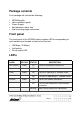
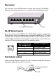
Package contents Your package will contain the following: • • • • • NP2008 switch User installation guide Power Supply Self adhesive rubber feet Wall mounting plugs and screws Front panel The front panel of the NP2008 switch contains LED’s corresponding to each network port located on the back of the hub: • 100 Mbps (10 Mbps). • Link/activity. • Plus a power LED. LED’s LABEL Pwr (Power) 100M Link/Act COLOUR STATUS Green On Power is connected to the device. Off Power has been disconnected.
Rear panel The rear panel of the NP2008 switch has eight auto-sensing 10/100 Mbps Ethernet ports and a power jack for connection of the supplied plug-pack. 8 x RJ45 10/100 Ports Power RJ-45 Network ports All of the ports on the NP2008 are 10/100 Mbps capable auto-sensing Ethernet ports. Each port supports only unshielded twisted pair (UTP) cable using an 8-pin RJ-45 plug. The NP2008 provides an UP-Link feature for cascading multiple switches.
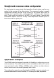
Straight and crossover cable configuration For two devices to communicate, the transmitter of each device must be connected to the receiver of the other device. The crossover function is usually implemented internally as part of the circuitry in the device. Most ports on switches and repeaters have media-dependent interfaces with crossover ports. These ports are referred to as MDI-X or normal ports.
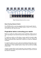
Basic Desktop Network with no server. Basic Desktop Network Switch The NP2008 switch is used as a desktop switch to build a small network that enables its users to have 100 Mbps access to other PC’s on the network and share files and resources. Preparation before connecting your switch Before you install your switch, prepare for the installation. Make sure you will be operating the unit within the specified voltage and temperature limits.
Attaching computers to the switch 1. 2. 3. Install a 10/100Mbps (10/100Base-TX) network adapter card into every computer you want to attach to the network. Make sure you install the Network adaptor drivers in accordance with the manufacturers directions. Prepare the twisted-pair cables with RJ-45 plugs on each end. Use Category 5/5e cable for all connections. Make sure the cable length is less than or equal to no more than 100 meters (328 feet).
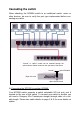
Cascading the switch When attaching the NP2008 switch to an additional switch, router or other devices, be sure to verify the port type implemented before connecting any cable. “Normal” or “Uplink” modes can be selected through the uplink selector switch located on the right side of the switch. Normal Uplink Enabled Right side view Uplink Select Switch A) Connecting the NP2008 to another NP2008: Your NP2008 switch supports a switch selectable UP-Link port, port 8 located on the rear of the switch.
1. 2. 3. 4. Locate the UP-Link slide switch located on the right hand side of the switch case. Slide the selection switch to the UP-Link position. Connect one end of a straight through cable to the number 8 port on the first NP2008 switch. Connect the other end of the straight through cable to any port of the second NP2008 switch, see previous diagram for more details.
Specifications of the switch Standard IEEE802.3 10Base-T Ethernet IEEE 802.3u & 802.3x 100 Base-TX Fast Ethernet Network Interface Eight 100BASE-TX / 10BASE-T N-Way ports Data Transfer Rate Ethernet: 10Mbps (half duplex) 20Mbps (full duplex) Fast Ethernet: 100Mbps (half duplex) 200Mbps (full duplex) Network Cable 10 BASE-T: Cat.3, 4 or 5 UTP Cables (100-ohm impedance) 100BASE-TX: Cat.
C-Tick Mark declaration of conformance This is to certify that this product complies with the Australian C-Tick standard where applicable. Warning Do not plug a phone jack connector into any of the RJ-45 port. This may damage the switch. Statement of conditions In the interest of improving internal design, operational function, and/or reliability, NetComm reserves the right to make changes to the product described in this document without notice.