Contents ABOUT THIS GUIDE ....................................................................................................................... 3 Purpose ................................................................................................................................... 3 Terms/Usage ........................................................................................................................... 3 Overview of this User's Guide ......................................................
ABOUT THIS GUIDE Congratulations on your purchase of the NetComm 16-port 10/100Mbps Fast Ethernet ProSwitch. This device integrates 100Mbps Fast Ethernet and 10Mbps Ethernet network capabilities in a highly flexible package. Purpose This guide discusses how to install your NetComm 16-port 10/100Mbps Fast Ethernet ProSwitch.
INTRODUCTION This chapter describes the features of the Switch and some background information about Ethernet/Fast Ethernet switching technology. Fast Ethernet Technology The growing importance of LANs and the increasing complexity of desktop computing applications are fueling the need for high performance networks. A number of high-speed LAN technologies have been proposed to provide greater bandwidth and improve client/server response times.
Switching LAN technology is a marked improvement over the previous generation of network bridges, which were characterized by higher latencies. Routers have also been used to segment local area networks, but the cost of a router, the setup and maintenance required make routers relatively impractical. Today switches are an ideal solution to most kinds of local area network congestion problems.
UNPACKING AND INSTALLATION This chapter provides unpacking and setup information for the Switch. Unpacking Open the shipping cartons of the Switch and carefully unpacks its contents.
Then, use screws provided with the equipment rack to mount each switch in the rack. Rev.1 - YML623 16-port 10/100Mbps Fast Ethernet ProSwitch www.netcomm.com.
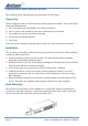
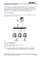
IDENTIFYING EXTERNAL COMPONENTS This section identifies all the major external components of the switch. Front Panel The figure below shows the front panels of the 16-port 10/100Mbps Fast Ethernet ProSwitch. LED Indicator Panel Refer to the detailed information about each of the switch's LED indicators. ■ Power (PWR) This indicator lights green when the switch is receiving power, otherwise, it is off.
USING THE PROSWITCH The NetComm16-port 10/100Mbps Fast Ethernet ProSwitch can be used to split parts of the network into different collision domains, making it possible to expand your Fast Ethernet network beyond the 205-meter network diameter limit for 100BASE-TX networks. Switches supporting both traditional 10Mbps Ethernet and 100Mbps Fast Ethernet are also ideal for bridging between the existing 10Mbps networks and the new 100Mbps networks.
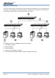
Segment Switching The 16-Port ProSwitch can segment a network into multiple connected pieces, increasing overall bandwidth and throughput.The following diagram illustrates the NetComm 16-Port ProSwitch segmenting networks that are built with the NetComm Swtich. Key: 1 = NetComm16-port 10/100Mbps Fast Ethernet ProSwitch 2 = 100 Mbps connection 3 = NetComm Switch 4 = NetComm Switch 5 = Servers with 100 Mbps connection 6 = PCs with network adapter installed, enabling 100 Mbps Connection www.netcomm.com.
Extending a Network Ethernet specifications limit the length of cable between hubs and PCs to 100 meters for a total diameter of 200 meters. By adding Fast Ethernet switches between hubs, the network is expanded by 200 Mbps with the addition of each switch. The follow diagram illustrates a network of NetComm Switch. Key: 1 = NetComm16-port 10/100Mbps Fast Ethernet ProSwitch 2 = 100 Mbps connection 3 = NetComm Fast Ethernet Switch 4 = PCs with 100 Mbps connection Rev.
TROUBLE SHOOTING Symptom Cause Solution Power LED is off. Power not received at Switch Check the power cord connections for the switch and the connected device. Check for a defective adapter card, cable, or port by testing them in an alternate environment where all products are functioning. Make sure all cables used are correct and comply with Ethernet specifications. Link LED is off or intermittent. Port connection is not functioning.
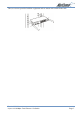
CONNECTOR PIN ASSIGNMENTS This appendix provides information about the RJ-45 plug and the vista RJ-45 connector used for the 16-Port Fast Ethernet ProSwitch. RJ-45 Plug In a Fast Ethernet network, it is important that all 100BASE-T certified Category 5 cabling use RJ-45 plugs. The RJ-45 plug accepts 4-pair unshielded twisted pair (UTP) or shielded twisted pair (STP) 100-ohm cable and connects into the vista RJ-45 connector. The RJ-45 plug connector is illustrated below.
CABLING GUIDELINES Fast Ethernet Cable Guidelines Fast Ethernet uses UTP cable, as specified in the IEEE 802.3u standard for 100BASE-TX. The specification requires Category 5 UTP cable consisting of either 2-pair or 4-pair twisted insulated copper conductors bound in a single plastic sheath. Category 5 cable is certified up to 100 MHz bandwidth. 100BASE-TX operation uses one pair of wires for transmission and the other pair for receiving and for collision detection.
Twisted Pair Cables For two devices to communicate, the transmitter of each device must be connected to the receiver of the other device. The crossover function is usually implemented internally as part of the circuitry in the device. Computers and workstation adapter cards are usually mediadependent interface ports, called MDI or uplink ports. Most repeaters and switch ports are configured as media-dependent interfaces with built-in crossover ports, called MDI-X or normal ports.
TECHNICAL SPECIFICATION General Standards IEEE 802.3 10BASE-T Ethernet IEEE 802.3u 100BASE-TX Fast Ethernet Protocol CSMA/CD Data Transfer Rate Ethernet: 10Mbps (half duplex), 20Mbps (full-duplex) Fast Ethernet: 100Mbps (half duplex), 200Mbps (full- duplex) Topology Star Network Cables 10BASET: 2-pair UTP Cat. 3,4,5, EIA/TIA- 568 100-ohm STP100BASE-TX: 2-pair UTP Cat.
REGISTERING YOUR NETCOMM PRODUCT To ensure that the conditions of your warranty are complied with, please go to the NetComm web site for quick and easy registration of your product at www.netcomm.com.au Alternatively, you can print out a copy of the Warranty Registration Form and mail it to NetComm Limited, PO Box 1200, Lane Cove NSW 2066. Note: The Warranty Registration Form can be found at “D:\Manuals\Warranty Registration Form.pdf” where D:\ is the letter of your CD-ROM drive.
WARRANTY The warranty is granted on the following conditions: 1. This warranty extends to the original purchaser (you) and is not transferable; 2. This warranty shall not apply to software programs, batteries power supplies, cables or other accessories supplied in or with the product; 3. The customer complies with all of the terms of any relevant agreement with NetComm and any other reasonable requirements of NetComm including producing such evidence of purchase as NetComm may require; 4.
All NetComm ACN 002 490 486 products have a standard 12 months warranty from date of purchase. However some products have an extended warranty option (refer to packaging). To be eligible for the extended warranty you must supply the requested warranty information to NetComm within 30 days of the original purchase by registering on-line via the NetComm web site at www.netcomm.com.au. NetComm reserves the right to request proof of purchase upon any warranty claim. Rev.