Contents ABOUT THIS GUIDE ................................................................................................................................ 4 Purpose ............................................................................................................................. 4 Terms/Usage...................................................................................................................... 4 INTRODUCTION...........................................................................
APPENDIX A Technical Specifications.................................................................................................... 38 APPENDIX B Cable Information ............................................................................................................. 41 RJ-45 Network Ports ....................................................................................................... 41 Straight and crossover cable configuration ...............................................................
ABOUT THIS GUIDE Congratulations on your purchase of the NP2500 24-Port 10/100 PoE + 2-Port 10/100/1000 WebSMART Switch. This Switch integrates 100Mbps Fast Ethernet and 10Mbps Ethernet network capabilities in a highly flexible package. Since this Switch’s Port-1 to Port-24 are Power over Ethernet (PoE) ports, it will automatically detect the presence of IEEE 802.3af-compliant devices and will provide power through these PoE ports. The Switch provides up to 15.
INTRODUCTION This chapter describes the features of the NP2500 24-Port 10/100 PoE + 2-Port 10/100/1000 WebSMART Switch and some background information about Fast Ethernet, Gigabit Ethernet, Switching, VLAN and Power over Ethernet technologies. Fast Ethernet Technology The growing importance of LANs and the increasing complexity of desktop computing applications are fueling the need for high performance networks.
Switching Technology Another approach to pushing beyond the limits of Ethernet technology is the development of switching technology. A switch bridges Ethernet packets at the MAC address level of the Ethernet protocol transmitting among connected Ethernet or Fast Ethernet LAN segments. Switching is a cost-effective way of increasing the total network capacity available to users on a local area network.
Features • 24×10/100Mbps Auto-negotiation Fast Ethernet RJ-45 ports PoE enabled • 2 x 1000BASE-T Gigabit Ethernet ports • Compliant with 802.3af specification • Supports PoE power up to 15.
UNPACKING AND INSTALLATION This chapter provides unpacking and installation information for the Switch. Unpacking Open the shipping cartons of the Switch and carefully unpacks its contents.
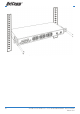
Installing the Switch on a Desktop When installing the Switch on a desktop or shelf, the rubber feet included with the Switch should first be attached. Attach these cushioning feet on the bottom at each corner of the device. Allow enough ventilation space between the Switch and any other objects in the vicinity. Figure 1. Installed on a Desktop Installing the Switch on a Rack The Switch can be mounted in an EIA standard-size, 19-inch rack, which can be placed in a wiring closet with other equipment.
Figure 3. Mount the Switch in the rack.
Connecting Network Cable The Switch supports 24 10/100BASE-TX Fast Ethernet PoE enabled ports and 2 1000BASE-T Gigabit Ethernet ports. These 24 PoE ports will be automatically activated when a compatible terminal is identified. The Switch will supply power through the PoE port to the connected PD. For Legacy devices that are not yet compatible, the PoE port will not offer the power to these devices.
AC Power The Switch uses the AC power supply 100-240V AC, 50-60 Hz. The power switch is located at the rear of the unit adjacent to the AC power connector and the system fan. The Switch’s power supply will adjust to the local power source automatically and may be turned on without having any or all LAN segment cables connected.
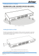
IDENTIFYING EXTERNAL COMPONENTS This chapter describes the front panel, rear panel, and LED indicators of the Switch. Front Panel The figure below shows the front panels of the Switch. Figure 5. Front panel view LED Indicator: Comprehensive LED indicators display the status of the Switch and the network (see the LED Indicators chapter below). 10/100Mbps PoE Ports (Port 1~24): These ports are PoE enable ports.
Rear Panel Figure 6. Rear panel of the Switch AC Power Connector: This is a three-pronged connector that supports the power cord. Plug in the female connector of the provided power cord into this connector, and the male into a power outlet. Supported input voltages range from 100-240V AC at 50-60Hz.
UNDERSTANDING LED INDICATORS The front panel LEDs provides instant status feedback, and helps monitor and troubleshoot when needed. Figure 7. LED indicators of the Switch System LEDs POWER On When the Power LED lights on, the Switch is receiving power. Off When the Power turns off or the power cord has improper connection. Power Maximum On (PWR MAX) CPU: Management Indicator When the system power resource remain <=15.
Red Off When the PoE port have the following failure happens: • PoE power circuit shortage. • Power over current: over the power current of PD’s classification. • Out of PoE voltage of 44 ~ 57 VDC output. • Cause fail. No PoE powered device (PD) connected or unplugged the PoE output port. Gigabit Ethernet Port Status LEDs Link/ACT: Link/Activity 1000Mbps 100Mbps 16 On When the Link/ACT LED lights on, the respective port is successfully connected to an Ethernet network.
CONFIGURATION Through the Web browser you can configure Switch functions such as VLAN, Trunking, and QoS… etc. With the attached Web Management Utility, you can easily discover all the Web Management Switches, assign the IP Address, changing the password, and upgrade new firmware. Installing the Web Management Utility The following instructions guide you through the installation of the Web Management utility. 1. Insert the Utility CD in the CD-ROM Drive. 2. The following screen will automatically appear.
Figure 8. Web Management Utility The Web Management Utility is divided into four parts, Discovery List, Monitor List, Device Setting, and Toolbar function, for detailed instructions, follow the sections below. Discovery List This is the list where you can discover all the Web management devices in the entire network. By pressing the “Discovery” button, you can list all the Web Management devices in the discovery list.
Monitor List All the Web Smart Devices in the Monitor List can be monitored; you can also receive the trap and show the status of the devices. System word definitions in the Monitor List: • S: Shows the system symbol of the Web-Smart device, represents a device system that is not alive. • IP Address: Shows the current IP address of the device. • MAC Address: Shows the device MAC Address. • Protocol version: Shows the version of the Utility protocol. • Product Name: Shows the device product name.
Figure 10. Trap information Note: In order to receive Trap information, the Switch has to be configured with Trap IP and Trap Events in the Web browser. These settings are available in the Trap Setting Menu. Add Item To add a device to the Monitor List manually, enter the IP Address of the device that you want to monitor. Delete Item To delete the device in the Monitor List. Device Setting You can set the device by using the function key in the Device Setting Dialog box.
Password Change You can use this when you need to change the password. Fill in the required passwords in the dialog boxes and press the “Set” button to process the password change immediately. Figure 12. Password Change Firmware Upgrade When the device has a new function, there will be a new firmware to update the device; use this function to upgrade the firmware. Figure 13.
Web Access Double click the device in the Monitor List or select a device in the Monitor List and press the “Web Access” button to access the device in Web browser. Toolbar The toolbar in the Web Management Utility has four main tabs: File, View, Options, and Help. File TAB In the “File TAB”, there is Monitor Save, Monitor Save As, Monitor Load, and Exit.
Configuring the Switch The Switch has a Web GUI interface for smart switch configuration. The Switch can be configured through the Web Browser. A network administrator can manage, control, and monitor the Switch from the local LAN. This section indicates how to configure the Switch to enable its smart functions including: Port Setting, VLAN Setting, Trunking Setting, Port Mirroring, PoE Setting, Status, Statistics, System Setting, Trap Setting, Password Setting, Backup Setting, Reset Setting.
Figure 16 Setup Menu When the main page appears, find the Setup menu on the left side of the screen (Figure 17). Click on the setup item that you want to configure. There are eleven options: Port Settings, VLAN Settings, Trunk Settings, Mirror Settings, SNMP Settings, PoE Settings, Device Status, Statistic, System Settings, Trap Setting, Password Settings, Backup Settings, and Reset Settings as shown in the Main Menu screen. Figure 17.
Configuring Setup Setting There are five items, including Port Settings, VLAN Settings, Trunk Settings, Mirror Settings, and PoE Settings in Setup menu. Port Settings In the Port Settings menu (Figure 18), this page will display each port’s status. Press the ID parameter to set each port’s Speed, Flow Control, QoS and Link Status. When you need to renew the posted information, press the “Refresh” button.
Speed/Disable: This setting has six modes—100M Full, 100M Half, 10M Full, 10M Half, Auto, and Disable—for speed or port disable selections. Flow Control: This setting determines whether or not the Switch will be handling flow control. Set FlowCtrl to Enable for avoiding data transfer overflow. If it is set to Disable, there is either no flow control or other hardware/software management.
VLAN Settings (Virtual Local Area Network) Group individual ports into a small “Virtual” network of their own to be independent of the other ports. To add a VLAN group, press “Add Group” button, the new VLAN configuration window will pop out, you can fill in the description in order to describe this VLAN Group, check on the port to be a member to this VLAN Group, and press “Apply” button to execute the setting. Figure 20. VLAN Group Settings Figure 21.
Trunk Setting The Trunk function enables to cascade two or more devices with a larger bandwidths. There are four Trunking groups to be set; and there are default ports in each member. Checked “Enable” to use the trunk function, select the ports in each member to be trunk, and click “Apply” to activate the selected trunk group. Figure 23. Trunk Settings Be sure that the selected trunk setting port must connect to the device with a same VLAN group.
Mirror Setting Port Mirroring is a method of monitoring network traffic that forwards a copy of each incoming and/or outgoing packet from one port of a network switch to another port where the packet can be studied. It enables the manager to keep close track of switch performance and alter it if necessary. Configuring the port mirroring by assigning a source port from which to copy all packets and a sniffer port where those packets will be sent.
PoE Setting When you click on the PoE Setting, the PoE Status will appear on the screen, it will display the PoE status including, Port Enable, Power limit, Power (W), Voltage(V), Current (mA), Classification, Port status, System Budget Power, Support Total Power, Remainder Power and The ratio of system power supply. Note: The PoE Status information of Power current, Power Voltage and Current are exist power usage information of connected PD, please “Refresh” to renew information. Figure 25.
Figure 26. PoE Port Setting Poe Enable: Select to enable or disable the PoE function. Power limit: This function let you to manually setting the port power current limitation to be given to the PD, to protect the Switch and the connected device, the power limit function will disable the PoE function of the port when the power over loaded. Select “<5W”, “<10W”, “<14W” and “Auto” for the power limit, the “Auto” will follow the classification from the PD power current.
Device Status Click on the “Status” button to display the device status on this screen. It will display the System Status, Port Status, VLAN Status, Trunk Status, Mirror Status and PoE Status. Press “Refresh” when you need to renew the posted information. Figure 28.
Statistic The Statistics Menu screen will display the status of each port packet count. Figure 29. Statistic For detailed packet information, click on the ID parameter as Figure 30. Figure 30.
System Setting The System Setting includes the System name, Location name, Login Timeout, IP Address, Subnet Mask and Gateway. Through the Web Management Utility, you can easily recognize the device by using the System Name and the Location Name. The Login Timeout is to set the idle time-out for security issue, when there is no action when running the Web Smart Utility and the time is up, you must re-login to Web Smart Utility before you set the Utility.
Trap Setting The Trap Setting enables the device to monitor the Trap through the Web Management Utility. Set the Trap IP Address of the manager where the trap is to be sent. Figure 32. Trap Setting System Events: Monitoring the system’s trap. Device Bootup: a trap when booting up the system. Illegal Login: a trap when there is using a wrong password login, and it will record from where the IP to be login. Twisted Pair Port Events: Monitoring the twisted pair port status.
Set Password Password is the invaluable tool for the manager to secure the Web Management Switch. You can use this function to change the password. If you forget the password, press the “Reset” button in the rear panel of the Switch. The current setting includes VLAN, Port Setting… etc. will be lost and the Switch will be restored to the default setting. Figure 33.Set Password Backup Setting The backup tools help you to backup the current setting of the Switch.
Reset Setting The Factory Reset button helps you to reset the device back to the default setting from the factory. Be aware that the entire configuration will be reset, the IP address of the device will be get from DHCP server (factory default is DHCP enabled) or got the default IP address of 192.168.0.1 when fail to get the IP address from DHCP server. Figure 35. Reset Setting Logout When you select this function, the Web configuration will log out and return to first Login page. Figure 36.
APPENDIX A Technical Specifications General Standards IEEE 802.3 10BASE-T Ethernet IEEE 802.3u 100BASE-TX Fast Ethernet IEEE 802.3ab 1000BASE-T Gigabit Ethernet IEEE 802.3x Full Duplex Flow Control IEEE 802.3af compliant Protocol CSMA/CD Data Transfer Rate Ethernet: 10Mbps (half-duplex), 20Mbps (full-duplex) Fast Ethernet: 100Mbps (half-duplex), 200Mbps (full-duplex) Gigabit Ethernet: 2000Mbps (full-duplex) Topology Star Network Cables 10BASET: 2-pair UTP Cat.
Temperature Operating: 0o ~ 40o C (32o ~ 104o F), Storage: -10o ~ 70o C (14o ~ 158o F) Humidity Operating: 10% ~ 90%, Storage: 5% ~ 90% Dimensions 440 x 310 x 44 mm EMI: FCC Class A, CE Mark Class A, VCCI Class A Safety: cUL(UL60950), CB(IEC60950) Performance Transmits Method: Store-and-forward Filtering Address Table: 4K entries per device Packet Filtering/Forwarding Rate: 10Mbps Ethernet: 14,880/pps 100Mbps Fast Ethernet: 148,800/pps 1000Mbps Gigabit Ethernet: 1,488,000/pps MAC Address Lea
c) Mechanical Loading- mounting of the equipment in the rack should be such that a hazardous condition is not achieved due to uneven mechanical loading. d) Circuit Overloading- Consideration should be given to the connection of the equipment to the supply circuit and the effect that overloading of circuits might have on over current protection and supply wiring. Appropriate consideration of equipment nameplate ratings should be used when addressing this concern.
APPENDIX B Cable Information This cable information is provided for your reference only. Please ensure you only connect the appropriate cable into the correct socket on either this product or your computer. If you are unsure about which cable to use or which socket to connect it to, please refer to the hardware installation section in this manual. If you are still not sure about cable connections, please contact a professional computer technician or NetComm for further advice.
In a straight-through cable, wires 1,2,3,4,5,6,7 and 8 at one end of the cable are still wires 1~8 at the other end. In a crossover cable, the wires of 1,2,3,6 are reversed so that wire 1 become 3 at the other end of the cable, 2 becomes 6, and so forth. To determine which wire is wire 1, hold the RJ-45 cable tip with the spring clip facing towards the ground and the end pointing away from you. The copper wires exposed upwards to your view. The first wire on the far left is wire 1.
APPENDIX C Registration and Warranty Information All NetComm Limited (“NetComm”) products have a standard 12 month warranty from date of purchase against defects in manufacturing and that the products will operate in accordance with the specifications outlined in the User Guide. However some products have an extended warranty option (please refer to your packaging).
• Connect the equipment to an alternate power outlet on a different power circuit from that to which the receiver/TV is connected. • Consult an experienced radio/TV technician for help. (3) The power supply that is provided with this unit is only intended for use with this product. Do not use this power supply with any other product or do not use any other power supply that is not approved for use with this product by NetComm.
NP2500 24-Port 10/100 PoE + 2-Port 10/100/1000 WebSMART Switch User Guide YML842 Rev1 45