Contents 1. Introduction ....................................................................................................................................... 3 1.1 Unpacking ................................................................................................................................ 4 1.2 Installation .................................................................................................................................� 5 1.3 Initial set up for management ....................
1. Introduction The NP2624M switch is a high performance web-managed SNMP Layer 2 switch that provides users with 24 x 10/100Mbps Ethernet and 2 x 1000Mbps Gigabit ports. This Switch has SNMP management and remote control capabilities such as “Web Cluster”. The Gigabit module, which can be copper or fibre media, supports 1000BASE-SX, 1000BASE-LX or 1000BASE-T, allowing users to increase their network response time at gigabit speeds and with great flexibility.
1.1 Unpacking Open the shipping carton of the Switch and carefully unpack its contents, the carton should contain the following items: 4 • One NP2624M port Fast Ethernet Layer 2 Switch. • One Mounting Kit including 2 mounting brackets and screws. • Four rubber feet with adhesive backing. • One AC power cord. • One RS-232 cable. • One CD containing this User Guide.
1.2 Installation You can use the following guidelines when choosing a place to install the Switch. • The surface must support at least 3 kg. Do not place heavy objects on the Switch. • You must be able to visually inspect the power cord and AC power connector. • Ensure proper heat dissipation by making sure there is adequate ventilation around the Switch. Desktop or Shelf Installation: When installing the Switch on a desktop or shelf, the rubber feet included with the device should attached first.
1.3 Initial set up for management There are two methods of management; one is out-of-band management, where you connect your PC to the switch through an RS232 cable. The other method is in-band-management, where you also connect your PC to the switch, but do so through an Ethernet network either locally or remotely, or simply directly connect your PC and the switch with an Ethernet cable.
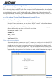
1.3.2 In-band Management through Ethernet In addition to terminal mode operation, the NP2624M switch also supports in-band management through a web browser. This function is much more user-friendly than terminal mode and can be performed either locally or remotely through Ethernet. Before you can access the switch: 1. You have to know the IP Address and Subnet Mask of both your switch and your PC.
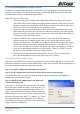
1.3.3 Telnet management In addition to local terminal mode operation, the NP2624M switch supports remote management through Telnet over a network or the internet without a web browser. In this mode, the user has to enter the same settings as required in in-band management to the IP Configuration before executing the Telnet program. Again, after properly setting the switch, save the settings and connect your Ethernet cable from your PC to any port of the Switch.
1.4 LED indicators information There are many LEDs on the front panel of switch. After the initial power on, these LEDs will reflect the current status within the switch as explained below: There is one power LED on the left side of the front panel. When power is applied, it turns green. Below it is a Diagnostic LED which will blink whilst conducting power-on diagnostics. There are two more FAN status LEDs beside the power LEDs.
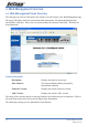
2. Web Management Function 2.1. Web Management Home Overview The first page you will see after login to the switch via a web browser is the Web Management page. This page will display the basic switch and module information. All information displayed in these fields is read-only. That is, the user cannot modify the contents of the fields. The fields are described below: Switch Information Description: Displays the name of device type.
2.2. Port status This page provides current status of every port and the negotiation result. State: Displays the port status: On or Down. “Unlink” will be treated as “off”. Link Status: Displays the link status. Down means “No Link”, Up means “Link”. Auto Negotiation: Displays the auto negotiation mode: auto/force/ Nway-force. Speed status: Displays the speed, port 1- 24 are 10/100Mbps, Port 25-26 are 10/100/1000Mbps. Duplex status: Displays full-duplex or half-duplex mode.
2.2.1 Single port counter and status The user can also click any port directly on the front panel of the Home Page to get single port status which is shown below. There is a flow rate historical chart on the right. The user can track the flow rate of this port for the last 60 hours. Changing the scale will re-calculate the chart.
2.3. Port Statistics Statistics pages are provided to monitor network traffic. They are: Port Summary, RMON Statistics(1), RMON Statistics(1) Graph, RMON Statistics(2). The above information provides a summary of the switch’s current status, including on/off state, link status, good or bad packets of transmitting and receiving, packets of transmitting abort, packets of collision and drop packets. The following pages provide the statistics of RMON 1,2,3,9 groups.
The second part collects the information about drop events, broadcast packets, multicast packets, alignment errors, undersize packets, oversize packets, fragments, jabbers and collisions. Press “Reset” button to clear the counter.
2.4. Show MAC Table The following information provides a table of the current MAC address that the switch has learned. Press “Prev” or “Next” button to browse previous 50 or next 50 items. The “Top” button will re-list the table from the first MAC. The table can be sorted by each of the headings by clicking the header on the top of table. For instance, clicking the “MAC” on the top of table will refresh the table by the index of “MAC”.
2.5. Administrator There are many management functions that can be set or performed if you click on Administrator on Home Page, including: 16 • IP and Management mode • Switch settings • Console port information • Port configuration • Trunking • IGMP and MAC Filter • VLAN configuration • Rapid Spanning tree • Port Mirror • SNMP • Security Manager • 802.
2.5.1. IP and Management mode The user can modify the switch IP Settings by entering the new values and clicking the “apply” button to confirm (save) these settings. Then reboot the switch and the new IP configuration values will be activated. The Management mode indicates which role this switch is currently playing. “Agent Slave” means it is treated as a normal switch. “Agent Master” means the “Single IP” is activated and the switch is treated as agent manager.
2.5.2 Switch Setting 2.5.2.1 Advanced MAC Address Age-out Time: Max bridge transit delay bound control: NOTE: 18 Type the number of seconds that an inactive MAC address remains in the switch’s address table. The valid range is 300~765 seconds. Default is 300 seconds. Limits the packets queuing time in switch. If enabled, the excess packets will be dropped. These valid values are 1 sec, 2 sec, and 4 sec and off. Default is 1 seconds.
Priority Queue Service settings: First Come, First Serve: The sequence of packets sent is depending on the arrival order. All High before Low: The high priority packets are sent before the low priority packets. WRR: (Weighted Round Robin) Select the preference given to packets in the switch’s high-priority queue. These options represent the number of high priority packets sent before one low priority packet is sent.
2.5.3 Console Port Information The Console is a standard UART interface which allows you to communicate with the Switch via a Serial Port. The user can use windows HyperTerminal program to link the switch.
2.5.4 Port Controls The user may modify or change mode operation in this page. Port: Select a port. State: User can disable or enable this port control. Negotiation: User can set auto negotiation mode to Auto, Nway (specify the speed/duplex on this port and enable auto-negotiation), Force of per port. Speed: User can set 100Mbps or 10Mbps speed on Port1~Port24. User can set 1000Mbps, 100Mbps or 10Mbps speed on Port25~Port26 (depends on module card mode).
Egress: Type the port effective egress rate. The valid range is 0~1000. The unit is 100K. 0: disable rate control. 1 ~ 1000: valid rate value. Priority: Enable or disable the port priority function. There are two priorities (high or low) provided if port priority is enabled. Security: A port in security mode will be “locked” without permission of address learning. Only the incoming packets with SMAC already existing in the address table can be forwarded normally.
2.5.5 Trunking The Link Aggregation Control Protocol (LACP) provides a standardized means for exchanging information between Partner Systems on a link to allow their Link Aggregation Control instances to reach agreement on the identity of the Link Aggregation Group to which the link belongs, move the link to that Link Aggregation Group, and enable its transmission and reception functions in an orderly manner.
Select the ports to join the trunking group. Allow a maximum of four ports to be aggregated at the same time. If LACP is enabled, you can configure LACP Active/Passive status in each port on State Activity page. Click Apply. 2.5.5.2 Aggregator Information When you are setting LACP aggregator, related information will be displayed. 1. This page displays no group active. LACP is not working. 2. This page displays Static Trunking groups. 3. This page displays Actor and Partner trunking in one group.
2.5.5.3 State Activity Active (select): The port automatically sends LACP protocol packets. N/A (no select): The port does not automatically send LACP protocol packets, and responds only if it receives LACP protocol packets from the opposite device. 1. A link that has either two active LACP ports or one active port can perform dynamic LACP trunking. A link has two N/A LACP ports will not perform dynamic LACP trunking because both ports are waiting for an LACP protocol packet from the opposite device. 2.
2.5.6 Filter Database 2.5.6.1. IGMP Snooping The NP2624M switch supports multicast IP. IGMP protocol can be enabled on this web page, and IGMP snooping information is displayed on this page. All multicast groups, VIDs and member ports are displayed in the list. IP multicast addresses range from 224.0.0.0 through 239.255.255.255. The Internet Group Management Protocol (IGMP) is an internal protocol of the Internet Protocol (IP) suite.
2.5.6.2. Static MAC Address When you add a static MAC address, it remains in the switch’s address table, regardless of whether the device is physically connected to the switch. This saves the switch from having to re-learn a device’s MAC address when the disconnected or powered-off device is active on the network again. 1. At the main menu, click Administrator >Filter Database >Static MAC Address. 2. In the MAC address box, enter the MAC address. 3. In the Port Number box, enter a port number. 4.
2.5.6.3 MAC filtering MAC address filtering allows the switch to drop unwanted traffic. Traffic is filtered based on the destination addresses. 1. In the MAC Address box, enter the MAC address that you want to filter. 2. If tag-based (802.1Q) VLAN are set up on the switch, in the VLAN ID box, type the VID to associate with the MAC address. 3. Click the Add. 4. Choose the MAC address that you want to delete and then click the Delete.
2.5.7. VLAN configuration A Virtual LAN (VLAN) is a logical network grouping that limits the broadcast domain. It allows you to isolate network traffic so only members of the VLAN receive traffic from the same VLAN members. Basically, creating a VLAN from a switch is logically equivalent to reconnecting a group of network devices to another Layer 2 switch. However, all the network devices are still plugged into the same switch physically. The NP2624M switch supports port-based, 802.
Support Tag-based VLAN (IEEE 802.1Q VLAN) Tagged-based VLAN is an IEEE 802.1Q specification standard. Therefore, it is possible to create a VLAN across devices from different switch venders. IEEE 802.1Q VLAN uses a technique to insert a “tag” into the Ethernet frames. Tag contains a VLAN Identifier (VID) that indicates the VLAN numbers.
2.5.7.1. Port Based VLAN 1. Click Add to create a new VLAN group. 2. Enter the VLAN name, group ID and select the members for the new VLAN. 3. Click Apply. 4. If there are many groups that over the limit of one page, you can click the “Next Page” to view other VLAN groups. NOTE: If trunk groups exist, they will be displayed (eg: TRK1, TRK2…) in select menu of ports. These can also be configured on the VLAN.
2.5.7.2. 802.1Q VLAN In this page, the user can create a Tag-based VLAN. 256 VLAN groups can be configured. If 802.1Q VLAN is enabled, then all ports on the switch will belong to the default VLAN (VID is 1). The default VLAN cannot be deleted. Basic Create a VLAN and add tagged member ports to it. 1. From the main menu, click Administrator >VLAN configuration, click Add and the following page will be displayed. 2. Type a name for the new VLAN.
3. Type a VID (between 2-4094). The default is 1. 4. Choose the protocol type. The NP2624M supports 802.1v with the implementation of Port-and-Protocol-based VLAN classification. Users can combine the field “Protocol VLAN” and the field of the port number to form a new VLAN group. NOTE: IEEE 802.1v allows a user to classify the packets through an untagged port. There are two possible strategies of the 802.1v support: Portbased VLAN and Port-and-Protocol-based VLAN. Both are supported in the NP2624M.
7. Use this page to set whether the outgoing frames are VLAN-Tagged frames or not. Then click Apply. Tag: outgoing frames with VLAN-Tagged. Untag: outgoing frames without VLAN-Tagged. Port VID From the main Tag-based (IEEE 802.1Q) VLAN page, click Port VID Settings to configure port VID settings. Port VID (PVID) Set the port VLAN ID that will be assigned to untagged traffic on a given port.
2.5.8. Rapid Spanning Tree We provide Both Rapid-Spanning-Tree-Protocol (RSTP) and Spanning-Tree Protocol (STP). The Spanning-Tree Protocol (STP) is a standardized method (IEEE 802.1D) for avoiding loops in switched networks. Enable STP to ensure that only one path at a time is active between any two nodes on the network. The Rapid-Spanning-Tree-Protocol (RSTP) is a more advanced Protocol than STP. RSTP can shorten spanning tree convergent time if your network topology changes.
3. You can also set new values for RSTP parameters, then click the Apply button to modify Parameter Description Priority You can change the priority value. A value is used to identify the root bridge. The bridge with lowest value has the highest priority and is selected as the root. Enter a number 1 through 65535. You can change the Max Age value. The number of second bridge waits without receiving Spanning-Tree Protocol configuration messages before attempting a reconfiguration.
4. The following parameters can be configured on each port , click the Apply button to modify Parameter Description Port Number Select the port number. Path Cost Specifies the path cost of the port that the switch uses to determine which ports are the forwarding ports. The lowest number is forwarding ports, the range is 1-65535 and default value base on IEEE802.
2.5.9. Port Mirror The Port Mirror is a method for monitoring traffic in switched networks. Traffic through ports can be monitored by one specific port. That is, traffic going in or out monitored ports will be duplicated into an Analysis port. Roving Analysis Mode: Press Space key to set mirror mode: Disable \Rx \Tx \Both. Analysis Port: This port can be used to see all monitored ports’ traffic. You can connect analysis port to LAN analyser or netxray. Monitored Port: The ports you want to monitor.
2.5.10. SNMP/Trap Manager Any Network Management platform running the Simple Network Management Protocol (SNMP) can manage the switch, provided the Management Information Base (MIB) is installed correctly on the management station. The SNMP is a Protocol that governs the transfer of information between management station and agent. 1. System Options: Use this page to define management stations as trap managers and to enter SNMP community strings.
2.5.11 Security Manager On this page, users can change username and password with following steps. 1. In User Name: Type the new username. 2. In Assign/Change password: Type the new password. 3. In Reconfirm password: Retype the new password. 4. Click Apply.
2.5.12 802.1x Configuration System Configuration 802.1x makes use of the physical access characteristics of IEEE802 LAN infrastructures in order to provide a means of authenticating and authorizing devices attached to a LAN port that has point-topoint connection characteristics, and prevent access to that port in cases where the authentication and authorization process fails. To enable 802.
Fu: Force the specific port to be unauthorised. Fa: Force the specific port to be authorised. Au: The state of the specific port was determined by the outcome of the authentication. No: The specific port didn’t support 802.1x function. Miscellaneous Configuration In this page, users can change the default configuration for the 802.1x standard: 42 Quiet Period: Used to define periods of time during which it will not attempt to acquire a supplicant (Default time is 60 seconds).
2.5.13 Ping The NP2624M switch provides a simplified ping function for users to check whether an IP is online or not. Enter the IP Address and number of counts for the ping packet to send. Press “Apply” to continue next page. This page will display the result of the pinging IP. It continues updating the “Reply Counts” to the ping packets that are sent. Users can interrupt the progress by clicking the “Stop” button.
2.5.14 Single IP The NP2624M switch provides a new management tool for a user to manage a group of LAN switches by an IP agent method. “Single IP” is the name, meaning that the administrator can access other network devices through one single IP device. There are two management modes: “Agent mode” and “Stacking mode”. Unlike a router’s NAT (from virtual IP domain to real IP domain), single IP provides a reverse access (from real IP domain to virtual IP domain) using an IP-forwarding technology.
Agent Control Port: The control port defines the specific TCP/UDP port the single IP switch is listening, which the agent manager sends its command to. Agent manager use this specific port to tell the single IP switch to change the current forwarding target host. The range of available port number is 28000 ~ 30000. Ignore the default settings of the “Agent Control Port” unless the user has a special need for this protocol port, such as virtual server. The default port number is 28019.
There are differences between “Remote Agent” and “Local Agent”. The “Local Agent”, referred to as “Local Single IP”, uses URL link method and the main browser window will directly jump to the target host. Since the URL of the web browser has changed, authentication will be requested once again when the new host is selected. Due to switch loading, only one remote user can access the agent manager at a time. Other users will be rejected if someone has launched the agent manager first.
Auto-discover method: Press “Find >>” and the found stackable switches will be gathered in “Auto Discover List”. Select these found members and press “ << Add” to add the selected hosts to the list. The searching range bases on Class C IP domain within Agent IP. Changing the “Agent IP” in “Administrator/IP & Management Mode” will alter the search range. For example, if the Agent IP is set to 192.168.223.100, and then the auto-discover function will search for available switches in the range from 192.168.
Launch Manager: This button launches the Stacking manager. For “Stacking mode”, there is an extra option “VLAN Mode” for user to choose which type of VLAN the stacking switch will carry on. There are “802.1Q” and “Port-base” VLAN . NOTE: In the case of the http:// authentication mechanism, the web browser will always ask the administrator to input username and password when agent manager changes a new host.
2.5.14.4 Stacking Manager This web UI provides not only the integrated VLAN management, but also a handy IP agent. The administrator can easily access other detail configurations in one individual switch of stacking set by clicking the hostname on the right side of this panel and jumping to its configuration webpage. Link Status The first page shows the current link status of all stacking members. Link-up port numbers will be highlighted.
As seen above, the VLAN name “ DEFAULT” and VID “ 1” is standard setting for general Tag VLAN , and all ports are added as untagged ports; The other VLAN “ 4091”, also called a “Stacking Tag VLAN”, is a unique setting for this type of stacking. All Giga ports are set to tag members to form a VLAN connection channel. WARNING: Stacking Tag VLAN is highly restricted. Incorrect operation can ruin the connection of stacking switches. Correct use of the Stacking Tag VLAN will be discussed in the next section.
The stacking switches interchange VLAN information through the Giga ports which are set to tagged members by “Stacking Tag VLAN”. New VLANs should keep their Giga ports tagged. Since the master switch holds all VLAN group information, the master switch should have the right to access the new VLAN by adding at least one Giga port to its tagged member. An exclusion of all master switch ports leads to unmanageability on this VLAN, for the master switch has no such VLAN in its internal table.
Edit or Delete a VLAN To edit an existing VLAN, just select the VLAN from the VLAN panel and modify the members in the Stacking Manager panel. Once done, press “ Apply” to submit the setting. To delete a VLAN is also an easy task. Select the unwanted VLAN and press “Delete” to remove it. NOTE: 52 The “DEFAULT VLAN” and “Stacking Tag VLAN” are undeletable! A error message will pop up to cancel the task. The Stack VLAN also cannot be edited.
PVID SETUP The default PVID value of all ports of 802.1Q VLAN is 1. Hence only the default VLAN ( PVID = 1 ) has all of its ports as members in the beginning. The available PVIDs are based on the VLANs that the user created in the previous “VLAN” page. 1. Select the PVID to be modified and choose the ports for this PVID value. 2. Click “Apply” button to submit and a message ”Please wait” will be displayed. 3. When a message advising “Current setting is on …” is displayed, the task is completed.
2.6. TFTP Update Firmware The following menu options provide some system control functions to allow a user to update firmware and remotely boot the switch system: 1. Install TFTP program (such as Turbo98, or Cisco TFTP) and then execute. 2. Copy the updated firmware image.bin into TFTP server’s directory. 3. In web management select administrator—TFTP update firmware. 4. Download the new image.bin file by pressing . 5. After the update has completed, press to restart the switch.
2.7. Configuration Backup 2.7.1. TFTP Restore Configuration Use this page to set the ftp server address. You can restore the EEPROM value from here, but you must restore the image in the ftp server, the switch will then download the flash image back. 2.7.2. TFTP Backup Configuration Use this page to set TFTP server IP address. You can save current EEPROM value from here, then go to the TFTP restore configuration page to restore the EEPROM value.
2.8. Reset System To Reset the Switch to its default configuration, click on the Reset button. 2.9. Reboot To Reboot the Switch System, click on the Reboot button. 2.10. Event Logging A history log is provided here to keep track of events occurring on the switch. This logs up to 100 events and then the latest event will overwrite the oldest one. All records will be kept in flash memory even after writing default, unless user clears the event log.
3. Console – Boot Loader Each time the switch restarts, the user can get some basic information from console (use Hyper terminal 57600 baud rate). After switch tests are done, a 5-seconds countdown timer will prompt the user to press any key to enter the “User Menu”. There are five functions in the menu: 1. start kernel: Back to switch system initiation and enter login. 2. kernel update from xmodem : Use 1k X modem to update firmware. 3. kernel update from tftp: Use TFTP to update firmware. 4.
3.1 1K X modem Firmware update We provide the 1k X modem to update firmware from RS232. 1K X modem only works in 57600bps mode. So you must change baud rate to 57600bps to download firmware. 1. Select “2” to start 1K X modem firmware update. 2. When “CCCC…” is displaying on console, select Transfer /Send File. 3. Select the 1K Xmodem in the Protocol item, and browse for the image for updating. Press the Send button. 4. Start downloading the image file. 5.
3.2 TFTP Firmware update We provide the TFTP client to update firmware from Ethernet. The user has to first install TFTP server on their PC and place the image in the download folder. 1. Press “3” to start TFTP update firmware. 2. Enter the Switch IP address and press “Enter” to accept default value. 3. Enter the TFTP Server IP address and press “Enter” to accept default value. 4. Enter the File name to download.
3.4 Diagnose Sdram We provide a basic diagnosis for a SDRAM test. It is important to verify hardware faults when a switch becomes unstable. When the test is done, it will display the status and prompt the user to reset the switch.
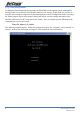
4. Out-of-band Terminal mode management The NP2624M switch also provides a serial interface to manage and monitor the switch. Users can follow the Console Port Information provided online to use Windows HyperTerminal program to link to the switch. Type the username and press enter and then type the password and press enter to login. The default username is “admin”; the default password is “admin ”.
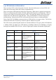
4.1 Main Menu There are six items which can be selected: Switch Static Configuration: Configure the switch. Protocol Related Configuration: Configure the protocol function. Status and Counters: Show the status of the switch. Reboot Switch: Restart the system or reset switch to default configuration. TFTP Update Firmware: Use TFTP to download a firmware image. Logout: Exit the menu line program.
4.2 Switch Static Configuration Control Keys You can press the Tab or Backspace keys to choose an item, and press the Enter key to select an item. Action Menu Line : Exit the configuration page and return to the previous menu. : Configure all items. When you have finished configuring the item, press Ctrl+A to return back to the action menu line. : Save all configured values. : Return to previous page to configure. : Go to the next page to configure it.
4.2.1. Port Configuration This page allows you to change the status of every port. Press the Space key to change the configuration of each item. InRate (100K/unit): OutRate (100K/unit): Enabled: Auto: Spd/Dpx: Flow Control: 64 User can set input rate control, which is 100K per unit. The valid range is 0~1000. 0: disable rate control. 1~1000: valid rate value. User can set output rate control, which is 100K per unit. The valid range is 0~1000. 0: disable rate control. 1~1000: valid rate value.
NOTE: Pressing “Save” will only save one page of configuration. If static trunk groups exist, they will be displayed (eg: TRK1, TRK2…) after port 26, and you can configure them as above. 4.2.2. Trunk Configuration This page allows the user to create a maximum of seven trunk groups. Users can arbitrarily select up to four ports from port 1~port 26 to build a trunk group. 1. Select on the actions menu 2. Press space key to configure the member port of trunk group.
4.2.3. VLAN Configuration 4.2.3.1. VLAN Configure This page allows the user to set VLAN mode to port-based VLAN or 802.1Q VLAN or disable VLAN function. NOTE: Changing the VLAN mode requires the switch to be restarted. If the switch is set to 802.1Q VLAN, this page will allow the user to set PVID, ingress filtering 1 and ingress filtering 2.
1. PVID (Port VID: 1~255): Type the PVID. 2. Ingress Filter 1 NonMember Pkt: NonMember Pkt works the same as Ingress Filtering Rule 1 on the web interface. Forwarding only packets with VID matching this port’s configured VID. Press Space key to choose “forward” or to “drop” the frame not matching this port’s configured VID. 3. Ingress Filter 2 UnTagged Pkt: UnTagged Pkt works the same as Ingress Filtering Rule 2 on the web interface. Drop untagged frame.
4.2.3.2. Create a VLAN Group Create Port-Based VLAN Create a port-based VLAN and add member/nonmember ports to it. 1. Select . 2. VLAN Name: Type a name for the new VLAN. 3. Grp ID: Type the VLAN group ID. The group ID range is 1~4094. 4. Member: Press key to choose VLAN member. There are two types to select: a. Member: the port is member port. b. No: the port is NOT member port. 5. Press Ctrl+A go back action menu line. 6. Select to save all configure value.
Create 802.1Q VLAN Create an 802.1Q VLAN and add tagged /untagged member ports to it. 1. Select . 2. VLAN Name: Type a name for the new VLAN. 3. VLAN ID: Type a VID (between 1~4094). The default is 1. There are 256 VLAN groups available. 4. Protocol VLAN: Press the Space key to choose the protocol type. 5. Member: Press the Space key to choose a VLAN member. There are three types to select: a. UnTagged: This is the member port of the VLAN group and outgoing frames are NO VLAN-Tagged frames. b.
4.2.3.3. Edit / Delete a VLAN Group In this page, users can edit or delete a VLAN group. 1. Press or item. 2. Choose the VLAN group that you want to edit or delete and then press enter. 3. Users can modify the protocol VLAN item and the member ports are tagged or untagged and remove some member ports from this VLAN group. 4. After editing the VLAN, press the key to save all configuration values. NOTE: 1. Pressing “Enter” once will complete the deletion when in delete mode. 2.
4.2.3.4. Groups Sorted Mode In this page, users can select VLAN groups sorted mode: (1) Sorted by Name (2) Sorted by VID. The Edit/Delete a VLAN group page will display the result. In the Edit/Delete a VLAN Group page, the result of sorted by name.
In the Edit/Delete a VLAN Group page, the result of sorted by VID.
4.2.4. Miscellaneous Configuration 4.2.4.1. Ping Type the Host IP and the counts for pinging, then go back to action menu and press “Save”. “Reply Counts” will display the result of pinging.
4.2.4.2. MAC Age Interval Type the number of seconds that an inactive MAC address remains in the switch’s address table. The valid range is 300~765 seconds. Default is 300 seconds. 4.2.4.3. Broadcast Storm Filtering This page configures the broadcast storm control. 1. Press to configure the broadcast storm filter mode. 2. Press Space key to choose the threshold value. The valid threshold value is 5%, 10%, 15%, 20%, 25% and NO. Default is 5%.
4.2.4.4. Maximum bridge transmit delay bound 1. Max bridge transmit delay bound: Limits the packets queuing time in switch. If enabled, when the amount of time the packets queued exceeding the maximum they will be dropped. Press the Space key to set the time. Those valid values are 1sec, 2sec, and 4sec and off. Default is off. 2. Low Queue Delay Bound: Limits the low priority packets queuing time in switch.
4.2.4.5. Port Security A port in security mode will be “locked” without permission of address learning. Only the incoming packets with SMAC already existing in the address table can be forwarded normally. The user can disable the port from learning any new MAC addresses, then use the static MAC addresses screen to define a list of MAC addresses that can use the secure port. 1. Select . 2. Press Space key to choose enable / disable item. 3. Press Ctrl+A to go back action menu line. 4.
4.2.4.6. Hash Algorithm Select CRC-Hash(default) or DirectMap for Hash algorithm. 4.2.4.7. IFG Compensation Enable or disable the inter-frame gap (IFG) compensation function.
4.2.5. Administration Configuration 4.2.5.1. Change Username This page allows the user to change the web management username. Type the new username, and then press item.
4.2.5.2. Change Password This page allows the user to change the web management login password. 4.2.5.3. Device Information This page allows the user to configure the device information.
4.2.5.4. IP Configuration This page allows the user to configure the IP settings and fill in the new values.
4.2.6. Port Mirror Configuration Port mirroring is a method for monitoring traffic in switched networks. Traffic through ports can be monitored by one specific port. That is, traffic going in or out of monitored ports will be duplicated into the monitoring port. Press the Space key to change configure of per item. 1. Select . 2. Sniffer Mode: Press the Space key to set the sniffer mode to Disable,Rx,Tx or Both. 3. Monitoring Port: The sniffer port can be used to see all monitored ports traffic.
4.2.7. Priority Configuration 4.2.7.1. Port Static Priority This static priority based on the port, if you set the port to high priority, incoming frames from this port will always be considered to be high priority frames.
4.2.7.2. 802.1P Priority Configuration There are 0~7-priority levels that can be mapped to a high or low queue. 1. Select . 2. Press Space key to select the priority level mapping to high or low queue. 3. High/Low Queue Service Ration H/L: User can select the ratio of high priority packets and low priority packets. 4. Press Ctrl+A to go back action menu line. 5. Select to save all configured values.
4.2.8. MAC Address Configuration 4.2.8.1. Static MAC Address When you add a static MAC address, it remains in the switch’s address table, regardless of whether the device is physically connected to the switch. This saves the switch from having to re-learn a device’s MAC address when disconnected or powered-off. In this page users can add / modify / delete a static MAC address.
Add static MAC address 1. Press > key to add static MAC address. 2. MAC Address: Enter the MAC address which the port should permanently forward traffic, regardless of the device’s network activity.
3. Port num: Press the key to select the port number. 4. Vlan ID: If tag-based (802.1Q) VLAN are set up on the switch, static addresses are associated with individual VLANs. Type the VID to associate with the MAC address. 5. Press Ctrl+A to go back action menu line. 6. Then select to save all configure value. Edit static MAC address 1. Press key. 2. Choose the MAC address that you want to modify and then press enter. 3. Press key to modify all the items. 4.
4.2.8.2. Filtering MAC Address MAC address filtering allows the switch to drop unwanted traffic. Traffic is filtered based on the destination addresses. In this page users can add /modify /delete a MAC address filter. Add filter MAC address 1. Press > key to add a MAC address filter. 2. MAC Address: Type the MAC address to filter. 3. Vlan ID: If tag-based (802.1Q) VLAN are set up on the switch, type the VID to associate with the MAC address. 4.
Edit filter MAC address 1. Press key. 2. Choose the MAC address that you want to modify and then press enter. 3. Press key to modify all the items. 4. Press Ctrl+A to go back to the action menu line, and then select to save all configured values. Delete filter MAC address 1. Press key to delete a filter MAC address. 2. Choose the MAC address that you want to delete and then press enter. 3. Pressing once will complete the deletion when in delete mode.
4.3.
4.3.1. RSTP The Rapid-Spanning-Tree Protocol (RSTP) is a standardized method (IEEE 802.1w) for avoiding loops in switched networks. RSTP is enabled, to ensure that only one path at a time is active between any two nodes on the network. 4.3.1.1. Enable/Disable RSTP This page allows the user to enable or disable the Spanning Tree function. Press the Space key to select enable or disable. 4.3.1.2. RSTP System Configuration 1. You can view spanning tree information about the Root Bridge on the left. 2.
4.3.1.3. Per port Configuration 1. PortState: Displays spanning tree status about the switch which per port is forwarding or blocking. 2. Select . 3. PathCost: Specifies the path cost of the port that the switch uses to determine which ports are the forwarding ports. 4. Priority: The Priority Port allows you to make it more or less likely to become the root port. 5. EdgePort: If the port connected to a device does not understand STP or RSTP, you can set as “No”.
4.3.2. SNMP Any Network Management running the simple Network Management Protocol (SNMP) can be managed by the switch. Use this page to define management stations as trap managers and to enter SNMP community strings. Users can also define a name, location, and contact person for the switch. 4.3.2.1. System Options 1. Press . 2. System Name: Type a name to be used for the switch. 3. System Contact: Type the name of contact person or organization. 4. System Location: Type the location of the switch. 5.
4.3.2.2. Community Strings Use this page to Add/ Edit/ Delete SNMP community strings. 1. Community Name: The name of current strings. 2. Write Access: Enable the rights as read only or read-write. Restricted: Read only, enables requests accompanied by this string to display MIB-object information. Unrestricted: Read write, enables requests accompanied by this string to display MIB-object information and to set MIB objects. Add Community Name 1. Press > key. 2.
Edit Community Name 1. Press the key, choose the item that you want to modify and then press Enter. 2. Community Name: Type the new name. 3. Write Access: Press the key to toggle between restricted or unrestricted. Delete Community Name 1. Press the key. 2. Choose the community name that you want to delete and then press enter. 3. Pressing once will complete the deletion when in delete mode.
4.3.2.3. Trap Managers A Trap Manager is a management station that receives traps; the system alerts generated by the switch. If no trap manager is defined, no traps are issued. Create a trap manager by entering the IP address of the station and a community string. Add SNMP trap manager 1. Press > to add the trap manager. 2. IP: Type the IP address. 3. Community Name: Type the community name. 4. Press Ctrl +A to go back to the action line menu and press key to save the configuration.
Edit trap managers 1. Press the key, and then choose the item that you want to modify. 2. IP: Type the new IP address 3. Community Name: Type the community name. 4. Press Ctrl +A to go back to the action line menu and press key to save configuration. Delete trap manager 1. Press the key. 2. Choose the trap manager that you want to delete and then press enter. 3. Pressing once will complete deletion when in delete mode.
4.3.3. IGMP The Internet Group Management Protocol (IGMP) is an internal protocol of the Internet Protocol (IP) suite. This page allows you to enable / disable the IGMP support. 1. Select . 2. IGMP Protocol: Press Space key to choose Enable / Disable. 3. IGMP Query Mode: Press Space key to choose Auto / Enable /Disable. 4. Press Ctrl+A to go back to the action menu line. 5. Select to save configured values.
4.3.4. LACP (Link Aggregation Control Protocol) This page allows you to configure and view the LACP status. NOTE: All ports support LACP dynamic trunk group. If connecting to the device that also supports LACP, the LACP dynamic trunk group will be created automatically. 4.3.4.1. Working Port Setting This page allows you to set work ports in trunk groups. 1. Select . 2. Group: Displays the trunk group ID. 3. LACP: Displays the trunk group’s LACP status.
4. LACP Work Port Num: Defines the maximum number of ports that can be aggregated at the same time. If local static trunk group, the number must be the same as group member ports. NOTE: Before changing settings on this page, you have to set trunk group on the page of Trunk Configuration first. 4.3.4.2. State Activity 1. Select . 2. Press the Space key to choose the item. Active: The port automatically sends LACP protocol packets.
4.3.4.3. LACP Status Relational Information for trunk groups can be found on this page. Static trunk group LACP trunk group 100 : Exit this page and return to previous menu. : Return to previous page to view. : Go to the next page to view.
4.3.5. 802.1x Protocol In this page the user can configure and view all the 802.1x status. 4.3.5.1. Enable/Disable 802.1x 1. Select . 2. Press the Space key to choose Enabled / Disabled. 3. Press Ctrl+A to go back to the action line menu. 4. Select to save configured values.
4.3.5.2. 802.1x System Configuration 1. Press . 2. Radius Server IP Address: the IP address of the authentication server. 3. Shared Key: A key shared between this switch and authentication server. 4. NAS, Identifier: A string used to identify this switch. 5. Server Port: The UDP port number used by the authentication server to authenticate. 6. Accounting Port: The UDP port number used by the authentication server to retrieve accounting information. 7. Press Ctrl+A go back action menu line. 8.
2. Status: Press key to choose Fu / Fa / Au / No authorization status. 3. Press Ctrl+A to go back to the action line menu. 4. Select to save all configured values. Note: Fu: Force the specific port to be unauthorized. Fa: Force the specific port to be authorized. Au: The state of the specific port determined by the outcome of the authentication. No: The specific port didn’t support 802.1x function. 4.3.5.4. 802.1x Miscellaneous Configuration 1. Press . 2.
4.4. Status and Counters You can press the Tab or Backspace keys to choose items, and press the Enter key to select an item. 4.4.1. Port Status This page display every ports status 104 Link Status: Displays the ports as linked or not linked. InRate: Displays the input rate control (100K/unit) setting value. OutRate: Displays the output rate control (100K/unit) setting value.
Enabled: Displays whether the port is enabled or disable depending on user settings. Enabled will display “Yes”, disabled will display “No”. If the port is unlinked, it will be treated as “No”. Auto: Displays which Nway mode the port is linked on: Auto, Nway_Force, and Force. Spd/Dpx: Displays the port speed and duplex. FlowCtrl: In Auto / Nway force mode, displays whether the flow control status is enabled or not after negotiation.
4.4.3. System Information 106 MAC Address: The unique hardware address assigned by a manufacturer. Firmware Version: Displays the switch’s firmware version. ASIC Version: Displays the switch’s Hardware version. Module 1 Type: Displays the module 1 Type: 1000Tx or 100Fx ext. Depends on module card mode. Module 1 information: Displays the information saved in EEPROM of module1. Module 2 Type: Displays the module 2 Type: 1000Tx or 100Fx ext. Depends on module card mode.
4.5. Reboot Switch 4.5.1. Default To reset the switch to its default configuration, please refer to section 2-4-14. 4.5.2. Restart Reboots the switch.
4.6. TFTP Update Firmware This page allows the user to update the firmware or restore the EEPROM value or upload the current EEPROM value. 4.6.1. TFTP Update Firmware This page allows the user to use TFTP to update the firmware. 1. Start the TFTP server, and copy firmware update version image file to TFTP server. 2. Press on this page. 3. TFTP Server: Type the IP of TFTP server. 4. Remote File Name: Type the image file name. 5. Press Ctrl+A go to action line. 6.
7. Once saved, the image file will automatically update. 8. Restart switch. 4.6.2. Restore Configure File This page allows the user to restore EEPROM value, save previous image file, from TFTP server. 1. Start the TFTP server. 2. Press on this page. 3. TFTP Server: Type the IP of TFTP server. 4. Remote File Name: Type the image file name. 5. Press Ctrl+A go to action line. 6. Press key, it will start to download the image file. 7. Once saved, the image file will automatically update. 8.
5. Application Examples 5.1. VLAN application used with switch VLAN is a simple solution to protect your network against broadcast storming by creating segments based on Layer2 Ethernet information and avoiding the complexity and the heavy processing requirements of Layer3 IP based routers. As a result, each group of stations connect to separate Segmented Ports to form different isolated Broadcast Domains.
You can group users according to some shared characteristic, such as a common business function or a common protocol. A single switch may have several independent VLANs within it. Below is a example that R&D, Manufacturing and Administration group can be partitioned into different VLAN groups, members in different groups can’t talk directly, but they still share the same server, such as MRP server, printer server in Administration group…etc.
5.2. Trunking Application used with switch Trunking allows you to increase the available bandwidth between switches by grouping ports into a trunk. Trunking can also be used to connect servers to switches when higher bandwidth services are required. You can use trunking to improve the throughput between segments.
1. Reduce the demand of real IP (public IP). Since there are up to 32 devices which have a IP agent as “Single IP” switch, meaning that the switch becomes a network agent and handles all functions of these devices, MIS can reduce the number of hosts that are directly connected to internet, and make use of real IPs more efficiently. 2. Integrate network devices without modifying hardware or software. “Single IP” is a technique mainly based on application layer in OSI standard.
5.3.1 Typical setup of “Single IP-Agent mode” network: The basic rules to set up “Single IP”: 1. The “Agent IP” of master switch should be within the IP domain of the managed hosts. (slave switches) 2. The “Agent IP” should be the same as “Switch IP” if administrator is within the IP domain of slaves; On other hand, the “Agent IP” should be different from “Switch IP” if the administrator wants to manage the slaves across the IP domain.
2. Master and slave switches in different LAN domain. In this example, master will manage 2 slave switches and 1 router in other IP domain. The difference between the examples is that the administrator and master switch IP is in the other IP domain (192.168.1.0). Switch IP of master is 192.168.1.100. Set its management mode to “Agent Master”. According to the basic rule 1, the agent IP should be set in the same domain as slaves, that is, 192.168.223.100. The other procedures are the same as example 1.
LAN IP: 192.168.223.254 Gateway IP: 192.168.223.249 WAN IP: 211.23.53.250 Switch IP: 192.168.223.101 Gateway IP: 192.168.223.254 Switch IP: 192.168.223.102 Switch IP: 211.23.53.251 Gateway IP: 192.168.223.254 Agent IP: 192.168.223.100 Gateway IP: 211.23.53.
5.4. “Single IP - Stacking mode” application used with switch This switch provides traditional stacking mode to stack a maximum of 16 switches by cascading their Gigabit ports. This feature helps network administrators use one switch assigned as the master to manage the other stacked switches through the browser.
3. Easy adding or removal stacking member: All Stacking members can be easily added or removed through the network. By clicking on the UI, the administrator can quickly determinate which switch will join the stack, without adjusting the network connection in front of those switches. It saves time when trouble-shooting any network abnormality. 5.4.1 A guide to build up “Stacking Switches” Follow these steps to build up a set of “Stacking Switches”: 1. Connect switches with Giga port in serial sequence.
5.4.2 An Example of Port-Base Stacking VLAN Port-Base Stacking VLAN setting: Switch: Master (192.168.223.100) Slaves (192.168.223.110, 192.168.223.120, 192.168.223.130, 192.168.223.140, 192.168.223.150) PC: PC-0(192.168.223.99) on port 22 of Master (192.168.223.100) PC-1(192.168.223.92) on port 9 of Slave 4(192.168.223.140) PC-2(192.168.223.93) on port 23 of Slave 5(192.168.223.150) Port-Base VLAN Group: VLAN name : test VLAN ID : 10 Members: Port 22, 24 of Master (192.168.223.
Result: 1. PC-0 can access both PC-01 and PC-02. 2. PC-0 can only access PC-02 only. PC-01 will not reply.
5.4.3 Issue on Trunk and Stacking mode There are Two basic rules here: 1. Stacking members cannot and should not truck each other. 2. Stacking members can trunk with non-stacking members. The packet traffic between stacking members are transferred only through Giga module. Trunking between stacking members may cause the spanning tree protocol (STP) to alter the topology and change the routed ports. If this happens, Giga port traffic may break and the stacking mechanism will fail.
5.5 Compatibility on Virtual Server and “Single IP” There are practical applications on combinations of virtual server and single IP. The network administrator generally prefers a router to have a unique gateway to Internet and a “Single IP” to manage his network hosts both from LAN and WAN. This example offers an example of how to setup a virtual server with an agent/stacking switch. Example target: 1. Any client with port 80 (http) go to company’s default web server (example 192.168.223.80) 2.
Step 3: Set up an agent function mapping port (211.23.53.252:28019->192.168.223.90:28019) Step 4: Modify Master’s “Agent IP” to new IP other than its “Switch IP” (Important) According to the basic rule 2 of “Single IP”, if the administrator accesses the slaves from the Internet the master’s Switch IP should differ from its Agent IP. In this case, change Agent IP to 192.168.223.91 to meet the rule, even thought Switch IP and Agent IP are still within the same IP domain.
Appendix A: Glossary of Terms NUMBERS 10BASE-T 10BASE-T is Ethernet over UTP Category III,IV, or V unshielded twisted-pair media. 100BASE-TX The two-pair twisted-media implementation of 100BASE-T is called 100BASE-TX. 802.11g An IEEE standard for wireless local area networks. It offers transmissions speeds at up to 54 Mbps in the 2.4-GHz band. A Access point It is the hardware interface between a wireless LAN and a wired LAN. The access point attaches to the wired LAN through an Ethernet connection.
D DHCP Dynamic Host Configuration Protocol was developed by Microsoft a protocol for assigning dynamic IP addresses to devices on a network. With dynamic addressing, a device can have a different IP address every time it connects to the network. In some systems, the device’s IP address can even change while it is still connected. DHCP also supports a mix of static and dynamic IP addresses.
G Gateway A gateway links computers that use different data formats together. Group Groups consist of several user machines that have similar characteristics such as being in the same department. H HEX Short for hexadecimal refers to the base-16 number system, which consists of 16 unique symbols: the numbers 0 to 9 and the letters A to F. For example, the decimal number 15 is represented as F in the hexadecimal numbering system.
J JAVA Java is a programming language that is specially designed for writing programs that can be safely downloaded to your computer through the Internet without the fear of viruses. It is an objectoriented multi-thread programming best for creating applets and applications for the Internet, Intranet and other complex, distributed network. L LAN Local Area Network a computer network that spans a relatively small area sharing common resources.
Protocol Communication on the network is governed by sets of rules called protocols. Protocols provide the guidelines devices use to communicate with each other, and thus they have different functions. Some protocols are responsible for formatting and presenting and presenting data that will be transferred from file server memory to the file server’s net work adapter Others are responsible for filtering information between networks and forwarding data to its destination.
T (TCP/IP) Transmission Control Protocol/Internet Protocol is a widely used transport protocol that connects diverse computers of various transmission methods. It was developed y the Department of Defense to connect different computer types and led to the development of the Internet. Transceiver A transceiver joins two network segments together. Transceivers can also be used to join a segment that uses one medium to a segment that uses a different medium.
Appendix B: Cable Information This cable information is provided for your reference only. Please ensure you only connect the appropriate cable into the correct socket on either this product or your computer. If you are unsure about which cable to use or which socket to connect it to, please refer to the hardware installation section in this manual. If you are still not sure about cable connections, please contact a professional computer technician or NetComm for further advice.
Straight and crossover cable configuration There are two types of the wiring: Straight-Through Cables and Crossover Cables. Category 5 UTP/ STP cable has eight wires inside the sheath. The wires form four pairs. Straight-Through Cables has same pinouts at both ends while Crossover Cables has a different pin arrangement at each end. In a straight-through cable, wires 1,2,3,4,5,6,7 and 8 at one end of the cable are still wires 1~8 at the other end.
Appendix C: Registration and Warranty Information All NetComm Limited (“NetComm”) products have a standard 12 month warranty from date of purchase against defects in manufacturing and that the products will operate in accordance with the specifications outlined in the User Guide. However some products have an extended warranty option (please refer to your packaging).
Product Warranty The warranty is granted on the following conditions: 1. This warranty extends to the original purchaser (you) and is not transferable; 2. This warranty shall not apply to software programs, batteries, power supplies, cables or other accessories supplied in or with the product; 3. The customer complies with all of the terms of any relevant agreement with NetComm and any other reasonable requirements of NetComm including producing such evidence of purchase as NetComm may require; 4.