Contents Chapter 1: Introduction .................................................................................................. 3 The NetComm 11G 54Mbps Wireless Access Point ...................................... 3 Chapter 2: Planning Your Wireless Network ................................................................ 4 Network Topology ............................................................................................ 4 Roaming ...............................................................
Chapter 1: Introduction The NetComm 11G 54Mbps Wireless Access Point Congratulations on your purchase of the Netcomm 11G 54Mbps Wireless Access Point (AP). This product is designed specifically for high-speed wireless LAN environment needs. It is easy to configure and operate even for non-technical users. Instructions for installing and configuring this product are included in this manual.
Chapter 2: Planning Your Wireless Network Network Topology A wireless LAN is a group of computers, each equipped with one Instant Wireless Series adapter. Computers in a wireless LAN must be configured to share the same radio channel. The Instant Wireless Series adapters provide access to a wired LAN for wireless workstations. An integrated wireless and wired LAN is called an infrastructure configuration.
How to Make Your Wireless Network More Secure Wireless networks can be vulnerable to an outsider gaining access if the encryption settings are not set adequately. Some of the default security settings on some wireless hardware, and in Microsoft Windows, may allow access to your wireless network from other wireless devices. The concepts that are presented here are offered only as a guide, and may help make your wireless network more difficult for an outsider to gain access.
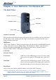
Chapter 3: Your NetComm 11G Wireless AP The Back Panel Antenna Connection INIT Button Selection Switch LAN Cable Power Input Antenna Connection Please install the external dipole antenna directly into the reversed SMA connector of AP. After the AP starts to work, you may adjust the angle of the antenna or reposition the AP to get a better performance and reach. INIT Button “INIT” means “Initiation”.
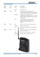
The Front Panel LED Color Status Description Power Green ON The AP power on OFF The AP power off ON 1) The AP is in normal operation mode 2) While in firmware upgrade process, it indicates the AP is writing the firmware into Flash ROM Blinking 1) The AP is in self-diagnostic mode. 2) While in firmware upgrade process, it indicates the AP is waiting the Wireless Navigator sending firmware image OFF 1) The AP starts to boot up the system.
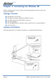
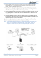
Chapter 4: Connecting the Wireless AP Before continuing, please ensure you have the following package contents ready for the hardware installation. Package Contents ■ ■ ■ ■ ■ ■ One Wireless Access Point One External Antenna with Reversed SMA Connector One UTP straight LAN Cable (RJ-45 connector) One Power Adapter One CD-ROM (Wireless Navigator utility software & user’s manual included) One User Guide Hardware Installation Following illustration is an example showing how to install AP with hub/switch.
1. Find an optimum location for the Access Point. The best place for the Access Point is usually at the center of your wireless network, with line of sight to all of your mobile stations. Placing the unit in the celing is ideal. 2. Fix the direction of the antenna. Try to place it in a position which can best cover your wireless network. Normally, the higher you place the antenna, the better the performance will be. The antenna's position enhances the receiving sensitivity. 3.
Chapter 5: Setting Up the Wireless Access Point Connecting the AP to your Network For optimal performance, usually the center of your wireless network is the best place for your AP, with line of sight to all of your mobile stations. Try to place it in a position where can best cover your wireless network and is away from any potential source of interference. And normally, the higher you place the AP, the better the wireless signal coverage will be.
TCP/IP Setup for Windows 98 and Millennium 1. Click the Start button, select Settings, and open the Control Panel. Inside the Control Panel, double-click the Network icon. 2. If the TCP/IP Protocol is listed for your network adapter, go to step five. Otherwise, click the Add button. 3. When the Component Type window appears, select Protocol and click the Add button. 4. Select Microsoft in the Manufacturers list and choose TCP/IP in the Network Protocols list. Then, click the OK button. 5.
TCP/IP Setup for Windows 2000 1. At the Windows 2000 desktop, right click My Network Places and select Properties. Then, right click Local Area Connection. Choose Properties. 2. If the TCP/IP Protocol is listed for your network adapter, go to step five. Otherwise, click the Install button. 3. When the Component Type window appears, select Protocol, and click the Add button. 4. Select Internet Protocol (TCP/IP) from the list and click the OK button. 5.
Installing the Wireless Navigator The Wireless Navigator Utility is provided to allow user(s) easily to configure the AP through any Windows-based PC over wired or wireless LAN port. This section describes procedures for installing the Wireless Navigator Utility to PC. 1. Insert the installation CD-ROM into the CD-ROM drive. Run SETUP.EXE program on the CD-ROM. 2. After the InstallShield Wizard preparation has completed finished, the Install Shield window will be shown. Click the Next button to continue. 3.
Startup and Login Follow the procedures below to startup Wireless Navigator and find the AP. Before you start the following procedure, please connect the Ethernet cable, connect the power cord, and then turn on the AP. All wireless clients should be requested to set the their SSIDs to the same as the AP SSID in advance before continuing. 1. Refer to previous section "Install the Wireless Navigator to your PC" in order to startup the configuration. 2.
Configuring the Access Point The Wireless Navigator includes nine tabs to help you customise your Access Point settings to fit your Network: ■ the Info tab ■ the Assoc tab ■ the Wireless tab ■ the Access tab ■ the Advanced tab ■ the Security tab ■ the IP Address tab ■ the Admin tab ■ the Help tab Rev. 1 - YML668 NP5400 11g Wireless Access Point User Guide www.netcomm.com.
The Info Tab The Info Tab displays the current AP settings. Access Point Information Access point name: Displays current device name of the AP. You also can change the name. MAC address of AP: Displays the unique fMAC number burned into this AP that identifies itself from other Ethernet devices Associated stations: Displays the number of wireless client devices associated with this AP. Wireless Firmware version: Displays the version number of wireless LAN firmware embedded in this AP.
The Assoc Tab The Assoc Tab displays all the wireless clients, which are currently associated with this AP. Mac address: Displays the list of the MAC address of associated wireless client.If you click the refresh button of your web browser, then the list will be updated. The Wireless Tab The Wireless Tab lets you select the network settings. Performance Mode: In Maximum interoperability mode, the AP will accept connections to both 802.11b and 802.11g client devices.
The Access Tab The Access Tab allows you to set the filter to specific wireless client device(s). Enable access control: If it is checked, the AP will start to filter any wireless client device with MAC address listed below. MAC address #: Please enter the MAC address of the wireless devices which need filtered in wireless LAN network. The device with same MAC address listed will not be able to associate with this AP. Note: Click button "Save" to store the settings.
The Security Tab The Security Tab displays 802.11b/g security and encryption options on this AP. WEP configuration: Display the Wired Equivalent Privacy security configurations Enable WEP: Enables the Wired Equivalent Privacy security function. WEP key length: Selects 64-bit or 128-bit WEP encryption. Be sure that the key length setting in the AP shall be the same as in wireless clients, or the communication will not work.
The IP Address Tab The IP Address Tab displays IP settings options on this AP. IP Address Mode: Select "Static" or "DHCP" mode. For "Static" mode, the IP address settings are given by user. For "DHCP" mode, these settings will be overridden by a DHCP server on your network. The default setting is "Static" Default IP Address: The static IP address you want to assign to the AP. The default value is "192.168.1.100". Default subnet mask: The subnet mask you want to assign for the AP.
The Admin Tab The Admin Tab allows to change the device's system configurations. Access point name: With this unque name, the AP can be found easily via Wireless Nevigator Utility. It can be the nickname assigned by the adminstrator. User name: This is the name used for login into the AP's built Web User Interface.
Firmware Upgrade Procedure 1. Click Start and select Programs, Wireless Navigator and then Wireless Navigator. Or, just double-click the Wireless Navigator icon on your desktop screen. 2. The Wireless Navigator starts up. 3. The computer starts searching for the Access Point and shows in the list. Choose the AP that you would like to upgrade the firmware, and use the right-click of the mouse to enter the "Upgrade FW" option 4. The download will begin.
Appendix A: Troubleshooting This section provides solutions to problems usually encountered during the installation and operation of the Access Point. Frequently Asked Questions Can the Access Point act as my DHCP Server? No. The Access Point is nothing more than a wireless hub, and as such cannot be configured to handle DHCP capabilities. Can I run an application from a remote computer over the wireless network? This will depend on whether or not the application is designed to be used over a network.
What is BSS ID? A specific Ad-hoc LAN is called a Basic Service Set (BSS). Computers in a BSS must be configured with the same BSS ID. What is ESSID? An Infrastructure configuration could also support roaming capability for mobile workers. More than one BSS can be configured as an Extended Service Set (ESS). Users within an ESS could roam freely between BSSs while maintaining a continuous connection to the wireless network stations and Access Points.
What is WEP? WEP is Wired Equivalent Privacy, a data privacy mechanism based on a shared-key algorithm, as described in the IEEE 802.11 standard. What is a MACAddress? The Media Access Control (MAC) address is a unique number assigned by the manufacturer to any Ethernet networking device, such as a network adapter, that allows the network to identify it at the hardware level. For all practical purposes, this number is usually permanent.
Appendix B: Glossary 802.11b One of the IEEE standards for wireless networking hardware. Products that adhere to a specific IEEE standard will work with each other, even if they are manufactured by different companies. The 802.11b standard specifies a maximum data transfer rate of 11Mbps, an operating frequency of 2.4GHz, and WEP encryption for security. 802.11b networks are also referred to as Wi-Fi networks. 802.11g Refers to the proposed of the IEEE 802.11 standard for wireless networking. The 802.
The lease time can vary depending on how long a user is likely to require the Internet connection at a particular location. It's especially useful in education and other environments where users change frequently. Using very short leases, DHCP can dynamically reconfigure networks in which there are more computers than there are available IP addresses. DHCP supports static addresses for computers containing Web servers that need a permanent IP address.
societies in special areas, such as the IEEE Computer Society. Infrastructure Network An infrastructure network is a group of computers or other devices, each with a wireless adapter, connected as an 802.11 wireless LAN. In infrastructure mode, the wireless devices communicate with each other and to a wired network by first going through an access point. An infrastructure wireless network connected to a wired network is referred to as a Basic Service Set (BSS).
mIRC mIRC runs under Windows and provides a graphical interface for logging onto IRC servers and listing, joining and leaving channels. Network Mask also known as the "Subnet Mask." OFDM Developed for wireless applications, Orthogonal Frequency Division Multiplexing (OFDM) technology offers superior performance-increased data rates and more reliable transmissions-than previous technologies, such as DSSS.
Subnet Mask The method used for splitting IP networks into a series of subgroups, or subnets. The mask is a binary pattern that is matched up with the IP address to turn part of the host ID address field into a field for subnets. TCP (Transmission Control Protocol) - A method (protocol) used along with the IP (Internet Protocol) to send data in the form of message units (datagram) between network devices over a LAN or WAN.
Appendix C: Specifications Standards: IEEE 802.11/11g and 802.11b standard compliant Antenna Single external antenna with reversed SMA connector Frequency Range 2.4-2.4835GHz ( Industrial Scientific Medical Band ) Operating Channels 11b Mode: 11 Channels (USA, Canada) 13 Channels (Europe, Australia) 14 channels (Japan) 11g Mode: 11 Channels (USA, Canada) 13 Channels (Europe, Japan, Australia) Modulation Technology CCK for 11b mode (1, 2, 5.
Registering your NetComm Product To ensure that the conditions of your warranty are complied with, please go to the NetComm web site for quick and easy registration of your product at www.netcomm.com.au Alternatively, you can complete the Warranty Registration Form on the following page and mail it to NetComm Limited, PO Box 1200, Lane Cove NSW 2066. Trademarks and Notices NetComm™ is a trademark of NetComm Limited. Windows® is a registered trademark of Microsoft Corporation.
Cut along the line Warranty Registration Form Date of Purchase ….......…………...........………................................. Name ….......…………...........………................................. Company ….......…………...........………................................. Address ….......…………...........………................................. …………………….........……........... Tel No ( ) ..............……….…. E-mail Post Code Fax No ( ) .....………....………. ....………...………. ….......…………...........………........................
Product Warranty The warranty is granted on the following conditions: 1. This warranty extends to the original purchaser (you) and is not transferable; 2. This warranty shall not apply to software programs, batteries, power supplies, cables or other accessories supplied in or with the product; 3. The customer complies with all of the terms of any relevant agreement with NetComm and any other reasonable requirements of NetComm including producing such evidence of purchase as NetComm may require; 4.
Specifications Standards IEEE 802.11/11g and 802.11b standard compliant Antenna Single external antenna with reversed SMA connector Frequency Range 2.4-2.4835GHz ( Industrial Scientific Medical Band ) Operating Channels 11b Mode: 11 Channels (USA, Canada) 13 Channels (Europe, Australia) 14 channels (Japan) 11g Mode: 11 Channels (USA, Canada) 13 Channels (Europe, Japan, Australia) Modulation Technology CCK for 11b mode (1, 2, 5.