Contents Introduction ...................................................................................................................................................4 About This Guide .....................................................................................................................................4 Features and Benefits .............................................................................................................................5 Package Contents .......................
Configuring the System ...............................................................................................................................48 Camera Configuration ...........................................................................................................................49 Mailing Configuration ...........................................................................................................................52 Proxy Server ...................................................
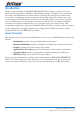
Introduction Thank you for purchasing the NS380/NS380W Pan/Tilt Internet Camera, a camera device that can be connected directly to an Ethernet or Fast Ethernet network. Compared to the conventional PC Camera, the Pan/Tilt Internet Camera features a built-in CPU and web-based solutions that can provide a cost-effective solution to transmit real-time high-quality video images and sounds for monitoring.
Features and Benefits Simple To Use The Pan/Tilt Internet Camera is a standalone system with built-in CPU requiring no special hardware or software such as PC frame grabber cards. The Pan/Tilt Internet Camera supports both ActiveX mode (for Internet Explorer users) and Java mode (for Internet Explorer and Netscape Navigator users). Therefore, all that is required is a web browser software such as Internet Explorer 5.0 or above or Netscape 6.0 or above.
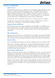
Package Contents Unpack the package and check all the items carefully. Your package should contain: • One NS380 or NS380W Pan/Tilt Internet Camera (NS380W model shown) • One metal mounting plate and screws • One Installation CD-ROM • One User Guide • One Package Contents Note • One AC power adapter • One RJ-45 Ethernet Cable If any item is damaged or missing, please contact NetComm immediately. Also, keep the box and packing materials in case you need to ship the unit in the future.
System Requirements For Networking Local Area Network: • 10Base-T Ethernet or 100Base-TX Fast Ethernet. Wireless Local Area Network for NS380W only): • IEEE 802.11g Wireless LAN. For Accessing the Camera Web Browser Users • Operating System: Microsoft® Windows® 98SE/ME/ 2000/XP • CPU: Intel Pentium II, 266 MHz or above • Memory Size: 32MB (64MB recommended) • Resolution: 800x600 or above • Microsoft® Internet Explorer 5.
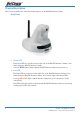
Physical Description This section describes the externally visible features of the Pan/Tilt Internet Camera. Front Panel 1. Power LED The Power LED is positioned on the right side of the Pan/Tilt Internet Camera’s lens while facing the Pan/Tilt Internet Camera. A steady BLUE light confirms that the Pan/Tilt Internet Camera is powered on. 2. Link LED The Link LED is positioned on the right side of the Pan/Tilt Internet Camera’s lens while facing the Pan/Tilt Internet Camera.
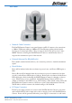
Rear Panel 1. Network Cable Connector The Pan/Tilt Internet Camera’s rear panel features an RJ-45 connector for connections to 10Base-T Ethernet cabling or 100Base-TX Fast Ethernet cabling (which should be Category 5 twisted-pair cable). The port supports the N-Way protocol and “AutoMDIX” function, allowing the Pan/Tilt Internet Camera to automatically detect or negotiate the transmission speed of the network. 2.
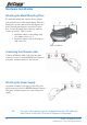
Hardware Installation Attaching the Metal Mounting Plate To attach the metal plate, remove the two rubber pads under the base of the camera firstly. Place the metal plate onto the camera base, and align the two holes of metal plate with two screw holes on the base. Secure the metal plate to the base with two screws (provided). Then, you can: (a) (b) 1. Install the camera to the ceiling using two ceiling screws (a); or, 2. Install the camera to the wall using two wall screws (b).
Security To ensure the highest security and prevent unauthorized usage of the Pan/Tilt Internet Camera the Administrator has the exclusive privilege to access the System Administration for settings and control requirements to allow users the level of entry and authorize the privileges for all users.
Using the Pan/Tilt Internet Camera The Pan/Tilt Internet Camera can be used in wide variety of applications. With the built-in CPU, it can work as a standalone system that provides a web-based solution, transmitting high quality video images and sounds for monitoring purposes. It can be managed remotely, accessed and controlled from any PC desktop over the Intranet or Internet via a web browser.
SOHO Applications Enterprise Applications NS380 / NS380W User Guide YML826 Rev1 - Pan/Tilt Internet Camera 13
Web Configuration Utility You can access and manage the Pan/Tilt Internet Camera through: 1) a web browser, and 2) the enclosed software IPView Pro. This chapter describes the Web Configuration Utility, and provides the instructions on using the camera with a web browser. Accessing the Camera with the Web Configuration Utility The Pan/Tilt Internet Camera must be configured through its built-in Web-based Configuration.
System Administration Under the Welcome screen of the Configuration Utility, click System Administration to enter the administration window that contains the settings required for the camera in the top menu bar, including Management, Configuration, Tools, Help, and Home. TIP: Once you have changed the settings in each option, click Save to store the settings, or Cancel to abandon, or Refresh to reload the status.
System Click the System item in the left column to display the device status of your camera. Device Status The information about the camera, including the Camera Name, Location, Model, Firmware Version, MAC Address and IP Address, can be found in this field. Ethernet Status You can monitor the networking status in this field, including the Link (network connection), Speed, and the Duplex mode. Video Click the Video item in the left column to display the video configuration of your camera.
Wireless (NS380W only) Click the Wireless item in the left column to display the information of the wireless LAN. Wireless Status The items in this field display the information of the wireless LAN, such as the Connection Mode (Infrastructure or Ad-Hoc), Link, SSID, Channel, Transmission Rate, and WEP Encryption. Network Click the Network item in the left column to display the information of the LAN.
User Click the User item in the left column to display the user(s) information. Active Users The items in this field display the user(s) information, including the user(s) IP address, Name, and DateTime.
System Administration > Configuration The Configuration window contains commands for settings that are required to input key details to setup the camera for operation. Click Configuration in the top menu bar and the Configuration window will appear as below: System Click the System item in the left column to setup the basic configuration of your camera. System Setting In this field, you can configure the basic information of your camera.
The default setting for administrator is blank space (Null String), and you need to key in the administrator name with a maximum length of 12 (printable ASCII) characters and enter the administrator password with a maximum length of 8 (printable ASCII) characters. It is highly recommended to set the Admin ID and Admin Password as soon as possible to enable security option for the Pan/Tilt Internet Camera to function. • LED Control: This option allows user to setup the LED illumination as desired.
Video Click the Video item in the left column to setup the image configuration of your camera. Video Setting In this screen, you can configure the basic information of your camera. • Video Resolution: Select the desired video resolution format, including 160x120, 320x240 (default) and 640x480. • Compression Rate: Select the desired compression rate with five levels from Very Low to Very High. Higher video compression rate will generate more compact file size with less video quality and vise-versa.
Wireless (NS380W only) Click the Wireless item in the left column to setup the wireless LAN configuration of your camera. Wireless Interface • Connection Mode: Use this option to determine the type of wireless communication for your camera. There are two choices of Infrastructure mode and Ad-Hoc mode. The default setting is Infrastructure. • SSID: The SSID (Service Set Identifier) is the name assigned to the wireless network.
To connect the camera to an Ad-Hoc wireless workgroup, make sure to set the same wireless channel and SSID to match with the PC/Notebook’s configuration for direct wireless communication. • Wireless Channel: This pull-down menu provides the wireless channel for communication. A “channel” is a range of frequencies to be used in communication between the camera and access point in Infrastructure mode, or the camera and PC/ Notebook in Ad-Hoc mode.
Advanced Setting In this field, you can setup more advanced configuration. 24 • Beacon Interval: This option defines time interval between two images sent. • Preamble: A preamble is a signal used in wireless environment to synchronize the transmitting timing including Synchronization and Start frame delimiter. Please NOTE that if you want to change the Preamble type into Long or Short, please check the setting of access point.
Network Click the Network item in the left column to setup the LAN configuration of your camera. TCP/IP The fields on this page represent the settings for the network in which the Pan/Tilt Internet Camera in installed. These are as follows: • IP Address Mode: This field provides your with three options to select the IP Address Mode: Fixed IP – You can select this option and enter the IP address directly. The default settings are: • IP Address – 192.168.0.20 • Subnet Mask – 255.255.255.
PPPoE – If your application requires a direct connection from an ADSL modem through the camera’s RJ-45 LAN port, click this option and enter the User ID and Password into the respective boxes. (You should have an ISP PPPoE account.) The camera will get an IP address from the ISP as starting up. 26 • DNS IP Address: DNS (Domain Name System) server is an Internet service that translates domain names into IP addresses. Enter at least one DNS IP Address in this field.
User Click the User item in the left column to add, edit and delete users for your camera. User Access Control • Access Control: The administrator has the authority to give permission for the privilege to control the device to users by selecting Enable or Disable. The default setting is No. Define Users Use this field to add or delete users for your camera. • Add User: Enter the user name in this box, and enter the user’s password assigned by the administrator.
DateTime Click the DateTime item in the left column to setup time and date for your camera, providing correct information for the remote users who might be thousands of miles away from the camera’s location. Date & Time You can set up time and date manually or automatically by selecting the Synchronized with Time Server option. • Synchronized with Time Server: Select this option and the time will be based on GMT setting. The time will be synchronized every 10 minutes.
Upload Click the Upload item in the left column to setup configuration for FTP server, time schedule and manual operation. FTP Server This field contains the following six basic settings for your FTP server. • Host Address: The IP Address of the target FTP server. • Port Number: The standard port number for the FTP server is Port 21, and it’s also the default setting. If the FTP server uses a specific port, please confirm the IT manager. • User Name: Enter the user name in this field.
Time Schedule Select the “Enable upload video to FTP server” option and enter the relevant information, such as the schedule, video frequency and base file name. • Schedule: You can 1.) Choose Always to always upload the video to FTP server, or 2.) Set the Schedule to manage the uploading task. In the Schedule option, you can set the Day and Time Period option. • Video Frequency: There are two ways to set the video frequency: 1.) Set Auto/1/2/3 frames per second, or 2.
E-mail Click the E-mail item in the left column to setup configuration for E-mail account, time schedule and manual operation settings. E-mail Account This field contains the following six basic settings for your FTP server. • SMTP Server Address: SMTP (Simple Mail Transfer Protocol) is a protocol for sending e-mail messages between servers you need to input the mail server address in this field. • Sender e-mail Address: Enter the e-mail address of the user who will send the e-mail.
System Administration > Tools The Tools window contains commands for restarting the camera. Click Tools in the top menu bar and the Tools window will appear as below: FTP Test Click the FTP Test item in the left column to test your FTP account. Test FTP Account Click the Test button to test the FTP account. E-mail Test Click the E-mail Test item in the left column to test your e-mail account. Test E-mail Account Click the Test button to test the e-mail account you provided.
Reset Do you really want to reset this device? Click the YES button from this option, and you can restart the camera just like turning the device off and on and saved settings are retained. If you do not want to reset the camera, exit this window without clicking YES. Factory Reset Do you really want to factory reset this device? Click the YES button from this option, and you can resume all factory default settings for the camera.
Backup Device Configuration to File Do you really want to backup the configuration to file? Click the Backup button from this option, and you can save the current configuration to file. Restore Device Configuration from File You can resume the device configuration from saved file in the computer. Click the Browse… button to point to the file, and then click Restore to start restoring.
System Administration > Help The Help window provides the basic information of the camera. Click Help in the top menu bar and the Help window will appear as below: About Displays the camera’s model name and version. Once the configuration is completed, click Home to return to the Welcome screen and select the desired View Video option either through ActiveX Mode or Java Mode as described in the next section. Then, position the camera to the desired location appropriately for your purpose.
Viewing Video To view video images from the browser, click View Video – ActiveX Mode or Java Mode from the Welcome screen to access the video images from your browser. View Image – ActiveX Mode and Java Mode Camera Name & Date/time: The Camera name and the current date/time will be displayed when the related information are entered under Configuration of Web Configuration Utility.
Controlling the Camera You can control the camera’s viewing angle through the control buttons on the left side of the viewing window. Control buttons Adjusting the Viewing Angle To adjust the camera’s viewing angle, simply click the Up/Down/ Left/Right button. Then, you can easily move the camera’s lens to focus on the object that you want. Clicking the Home button allows you return to the original position.
Using IPView Pro with the Pan/Tilt Internet Camera This chapter describes IPView Pro, which is a powerful software application designed with a userfriendly interface for ease of control and navigation requirements. Installation Step 1 Insert the CD-ROM into the CD-ROM drive to initiate the auto-run program. The menu screen will appear as below: Step 2 Click the Setup Camera button. The following screen is presented: Click the Install IPView Pro Utility button.
Step 3 Click the IPView Pro item to activate the InstallShield Wizard. Click Next in the welcome screen. Step 4 Read and accept the License Agreement; then, click Yes.
Step 5 Choose the destination location. If no specific requirement, leave the default setting and click Next. Step 6 The InstallShield Wizard starts to install the software, and the progress bar indicates the installation is proceeding.
Step 7 If you use Windows® 2000/XP, it will appear a Digital Signature warning screen. Click Continue Anyway (Windows® XP) or Yes (Windows® 2000). Windows® XP Windows® 2000 Step 8 Click Finish to complete the installation.
Getting Started This section describes the User Interface of IPView Pro, with detailed procedures for using the application. To launch IPView Pro, click Start > Programs > IPView Pro > IPView Pro. The main screen will appear as below: NOTE: IPView Pro requires the system’s resolution setting up to 1024x768. Please configure the resolution to 1024x768 or higher; otherwise, it may shows incomplete screen when launching the program. Item Feature NO.
View Window Show the camera’s view in this window. Select the view mode from these buttons. View Mode Buttons Show one camera in View Window. Show four cameras in View Window. Show six cameras in View Window with the first one as the major view. Show eight cameras in View Window with the first one as the major view. Show nine cameras in View Window. Show ten cameras in View Window with the first two as the major views. Show thirteen cameras in View Window with the first one as the major view.
Using IPView Pro Adding a Camera To add a camera: 1. Click the System Configure button to enter the System Configuration. If you are not sure of the camera’s IP address, you can click Search to search the available camera(s) within the network. 2. Select the camera you want by highlighting it, and then click Add Camera.
3. Click Save, and then click the System Configure button to return to View Window. The selected camera’s video will be displayed now. Alternately, you can add a camera by entering the its IP address directly: 4. Select the Input IP tab. 5. Enter the camera’s IP address (default: 192.168.0.20) and Port (default: 80), and then click Add Camera. 6. Click Save, and then click the System Configure button to return to View Window. The selected camera’s video will be displayed now.
Viewing a Camera From the View Modes of the panel, you can select one-camera mode or other modes to display your video. IPView Pro allows a maximum of 16 cameras for viewing. For example, if you use only one camera, select one-camera mode ( will display the view as figure 1. If there are four cameras, select four-camera mode ( view as figure 2. Figure 1. 46 ), and the View Window ), and the View Window will display the Figure 2.
Recording Video IPView Pro allows you to record the video clip and save it in your computer through the following methods: Manual Record, Schedule Record, and Motion Record. When you click the Record button and select Manual Record, it will start recording. Click the button again to stop. If you select Schedule Record or Motion Record, the system will record the video clip according to the settings in System Configuration.
Configuring the System Clicking the System Configure button on the panel allows you to configure the system settings, and the System Configuration Screen will appear in the View Window as shown below. Once configured, click Save to save the settings, and then click the System Configure button again to exit configuration.
Camera Configuration In this field, you can add/delete the camera (as described in the previous section). Also, you can configure the following settings: Web Configuration In the left column, selecting the Web Configuration item will launch the Web Configuration Utility in View Window. You can configure these settings according to the description in Chapter 5, Using the Camera. Click Back to exit the Web Configuration Utility.
- Detect Region: When you select the Full picture option, the camera will monitor the whole area. - Sensitivity Level: Move the slide bar to adjust the sensitivity level for detecting motion to record video. Motion Configuration-2 The Motion Configuration-2 item allows you to configure the alarm, e-mail notification and playing of a sound once motion is detected. 50 - Invoke Alarm: Select this option to enable alarm when some motion detected by the system.
Tools The Tools item allows you to reset the camera, reset to factory defaults, or update the camera’s firmware. - Reset: Restore the original setting of your camera. Do you really want to reset this device? Click Yes in the pop-up dialog box to confirm. - Factory Reset: Restore the factory default settings of the camera. Do you really want to factory reset this device? Click Yes in the pop-up dialog box to confirm.
Mailing Configuration When Motion Detection function is enabled and the Send e-mail option is checked, you should enter the required information in the respective fields. 52 - Mail Server: Enter the mail server address that is used to send your e-mail. - Mail From/To: Enter the sender’s/receiver’s e-mail address. - Subject: Enter the title of the e-mail. - User Name/Password: Enter the user name/password to login the mail server.
Proxy Server Check the Proxy Server option and enter the required settings in the Address and Port boxes to enable and use the Proxy Server function.
Recording Configuration In this field, you can configure the storage settings. - Log Storage: • Reserved HDD Space For MS-Windows OS: You can reserve 500 MB to 1000 MB hard disk space for the program. • Each Recording File Size: If the recorded video files reach the file size limit, video images will be recorded into another file automatically. The available settings are from 10 MB to 50 MB. • Storage List: The destination folder to save the recorded video file can be specified here.
- Week Mode: First, select the camera desired from the pull-down menu. Then, setup the time in the Start/Stop fields, and select the weekday from the buttons. Click Add to add the recording schedule to the list. Click Save to save the settings.
Others When multiple cameras connected, this option allows the system to display these views as the main view in circles according to your time settings. The range of Time interval of scan is from 1 to 20 seconds. Log List This filed displays the user(s) information, which include the Date, MAC address, and the brief description of events.
Account Change the Admin ID and Admin password using the fields on this page. Click the Login Password Check field to challenge users when they attempt to access the camera. About This filed provides information of the software application.
Appendix A: Frequently Asked Questions Pan/Tilt Internet Camera Features Q: What is an Pan/Tilt Internet Camera? A: The Pan/Tilt Internet Camera is a standalone system connecting directly to an Ethernet or Fast Ethernet network and supported by the wireless transmission based on the IEEE 802.11g standard.
Q: Can the Pan/Tilt Internet Camera be connected on the network if it consists of only private IP addresses? A: The Pan/Tilt Internet Camera can be connected to LAN with private IP addresses. Q: Can the Pan/Tilt Internet Camera be installed and work if a firewall exists on the network? A: If a firewall exists on the network, port 80 is open for ordinary data communication. However, since the Pan/Tilt Internet Camera transmits image data, the default port 8481 is also required.
Appendix B: PING Your IP Address The PING (Packet Internet Groper) command can determine whether a specific IP address is accessible by sending a packet to the specific address and waiting for a reply. It can also provide a very useful tool to confirm if the IP address conflicts with the Pan/Tilt Internet Camera over the network. Follow the step-by-step procedure below to utilize the PING command. However, you must disconnect the Pan/Tilt Internet Camera from the network first. 1. Start a DOS window. 2.
Appendix C: Trouble Shooting Q: I cannot access the Pan/Tilt Internet Camera from a web browser. A1: The possible cause might be the IP Address for the Pan/Tilt Internet Camera is already being used by another device. To correct the possible problem, you need to first disconnect the Pan/Tilt Internet Camera from the network. Then run the PING utility (follow the instructions in Appendix B - PING Your IP Address). A2: Another possible reason is the IP Address is located on a different subnet.
Q: Why does the Pan/Tilt Internet Camera work locally but not externally? A1: Might be caused from the firewall protection. Need to check the Internet firewall with your system administrator. A2: The default router setting might be a possible reason. Need to double check if the configuration of the default router settings is required.
Appendix D: Time Zone Table NS380 / NS380W User Guide YML826 Rev1 - Pan/Tilt Internet Camera 63
Appendix E: Adjust Pan/Tilt Internet Camera Focus To adjust the focus of the lens, you need to turn the lens slowly in either clockwise or anti-clockwise direction until the desired image appears. DO NOT over turn the lens in either of the directions, as it will be out of focus. NOTE: You can further adjust the Pan/Tilt Internet Camera’s image quality through System Administration – Image of Web Configuration. Please refer to Web Configuration section for further details.
Appendix F: Specification Video specification Resolution: Sensor: Lens: 640 x 480 pixel Color CMOS sensor f: 6.0 mm, F: 1.
Appendix G: Glossary of Terms NUMBERS 10BASE-T 10BASE-T is Ethernet over UTP Category III,IV, or V unshielded twisted-pair media. 100BASE-TX The two-pair twisted-media implementation of 100BASE-T is called 100BASE-TX. 802.11g An IEEE standard for wireless local area networks. It offers transmissions speeds at up to 54 Mbps in the 2.4-GHz band. A Access point It is the hardware interface between a wireless LAN and a wired LAN. The access point attaches to the wired LAN through an Ethernet connection.
D DHCP Dynamic Host Configuration Protocol was developed by Microsoft a protocol for assigning dynamic IP addresses to devices on a network. With dynamic addressing, a device can have a different IP address every time it connects to the network. In some systems, the device’s IP address can even change while it is still connected. DHCP also supports a mix of static and dynamic IP addresses.
G Gateway A gateway links computers that use different data formats together. Group Groups consist of several user machines that have similar characteristics such as being in the same department. H HEX Short for hexadecimal refers to the base-16 number system, which consists of 16 unique symbols: the numbers 0 to 9 and the letters A to F. For example, the decimal number 15 is represented as F in the hexadecimal numbering system.
J JAVA Java is a programming language that is specially designed for writing programs that can be safely downloaded to your computer through the Internet without the fear of viruses. It is an objectoriented multi-thread programming best for creating applets and applications for the Internet, Intranet and other complex, distributed network. L LAN Local Area Network a computer network that spans a relatively small area sharing common resources.
Protocol Communication on the network is governed by sets of rules called protocols. Protocols provide the guidelines devices use to communicate with each other, and thus they have different functions. Some protocols are responsible for formatting and presenting and presenting data that will be transferred from file server memory to the file server’s net work adapter Others are responsible for filtering information between networks and forwarding data to its destination.
T (TCP/IP) Transmission Control Protocol/Internet Protocol is a widely used transport protocol that connects diverse computers of various transmission methods. It was developed y the Department of Defense to connect different computer types and led to the development of the Internet. Transceiver A transceiver joins two network segments together. Transceivers can also be used to join a segment that uses one medium to a segment that uses a different medium.
Appendix H: Cable Information This cable information is provided for your reference only. Please ensure you only connect the appropriate cable into the correct socket on either this product or your computer. If you are unsure about which cable to use or which socket to connect it to, please refer to the hardware installation section in this manual. If you are still not sure about cable connections, please contact a professional computer technician or NetComm for further advice.
Straight and crossover cable configuration There are two types of the wiring: Straight-Through Cables and Crossover Cables. Category 5 UTP/ STP cable has eight wires inside the sheath. The wires form four pairs. Straight-Through Cables has same pinouts at both ends while Crossover Cables has a different pin arrangement at each end. In a straight-through cable, wires 1,2,3,4,5,6,7 and 8 at one end of the cable are still wires 1~8 at the other end.
Appendix I: Registration and Warranty Information All NetComm Limited (“NetComm”) products have a standard 12 month warranty from date of purchase against defects in manufacturing and that the products will operate in accordance with the specifications outlined in the User Guide. However some products have an extended warranty option (please refer to your packaging).
Product Warranty The warranty is granted on the following conditions: 1. This warranty extends to the original purchaser (you) and is not transferable; 2. This warranty shall not apply to software programs, batteries, power supplies, cables or other accessories supplied in or with the product; 3. The customer complies with all of the terms of any relevant agreement with NetComm and any other reasonable requirements of NetComm including producing such evidence of purchase as NetComm may require; 4.